416-107 - Air conditioner Anslut - Free user manual and instructions
Find the device manual for free 416-107 Anslut in PDF.


| Brand | Anslut |
| Model | 416-107 |
| Product Type | Portable Air Conditioner |
| Cooling Capacity | 9000 BTU/h (approx.) |
| Dehumidification Capacity | 1.5 L/h |
| Airflow Rate | 300 m³/h |
| Power Supply | 230 V ~ 50 Hz |
| Power Consumption (Cooling) | 900 W |
| Dimensions (W x D x H) | 330 x 350 x 700 mm |
| Weight | 28 kg |
| Refrigerant | R290 |
| Operating Modes | Cool, Fan, Dehumidify, Auto |
| Fan Speeds | Low, Medium, High |
| Timer | 24-hour programmable |
| Remote Control | Yes (battery included) |
| Noise Level | 54 dB(A) (max) |
| Filter Type | Washable mesh filter |
| Filter Cleaning | Every 2 weeks; rinse with water |
| Safety Features | Auto shut-off on overheat, compressor delay |
| Spare Parts Available | Filter, remote control, exhaust hose |
| Warranty | 2 years (Europe) |
Frequently Asked Questions - 416-107 Anslut
User questions about 416-107 Anslut
0 question about this device. Answer the ones you know or ask your own.
Ask a new question about this device
Download the instructions for your Air conditioner in PDF format for free! Find your manual 416-107 - Anslut and take your electronic device back in hand. On this page are published all the documents necessary for the use of your device. 416-107 by Anslut.
USER MANUAL 416-107 Anslut
Operating Instructions for Heat pump air/water
416-107
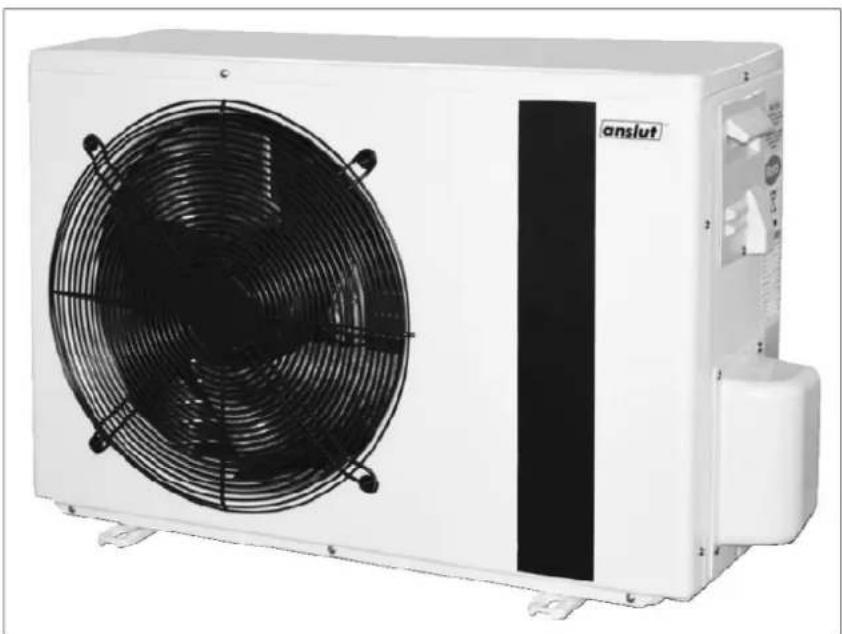
natural_image
Exterior view of a white industrial air conditioning unit with a black fan and control panel (no visible text or symbols)SV Bruksanvisning i original
NO Bruksanvisning i original
EN Operating instructions in original
SVENSKA 5
SÄKERHETSANVISNINGAR 5
Elsäkerhet 5
Allmänt 5
TEKNISKA DATA 6
BESKRIVNING 6
Inomhusenhet 6
Utomhusenhet....7
Manöverpanel 7
HANDHAVANDE 8
På/Av 8
Driftlägen....8
Temperatur+ 8
SAFETY INSTRUCTIONS....70
Electrical safety....70
General 70
TECHNICAL DATA....71
DESCRIPTION 71
Indoor unit 71
Outdoor unit 72
Control panel....72
OPERATION 73
On/Off 73
Operating modes 73
Temperature + 73
Timer/night reduction 73
Electric heater 74
Troubleshooting 74
Water pump 75
Capacity curve 76
Regulation....76
INSTALLATION TYPES 78
Heater with double casing 78
Direct connection to waterborne heating system....79
Heat source with shunt 80
Multifunction tank 81
WIRING DIAGRAM 82
INSTALLATION 83
Checklist when positioning the indoor and outdoor units 83
Module system....83
Tools needed 84
Indoor unit and control panel 84
Outdoor unit 85
Installation kit 85
Hole 86
Location of the outdoor unit 87
Brackets 87
Installation of outdoor unit 87
Pipe and cable routing 88
Routing refrigerant pipes 88
Pipe routing 89
Connecting the installation kit....89
Electrical connection, indoor unit 90
Electrical connection, outdoor unit....90
SÄKERHETSANVISNINGAR
natural_image
Technical line drawing of a mechanical assembly showing internal components and housing (no text or symbols)Vattenpump
line
| Label | Value | |-------|-------| | AUTO | High | | HD2 | Medium| | HD1 | Low | | BL2 | Medium| | BL1 | Low |natural_image
Collection of various hand tools laid out on a concrete floor, including pliers, wrenches, and a measuring tool (no text or symbols visible)natural_image
Isometric line drawing of a rectangular electronic device with a black tab and two ports (no text or symbols)
Utomhusenhet
natural_image
Close-up of a medical or industrial device with copper tubing and brass fittings, mounted on a white panel (no visible text or symbols)
natural_image
White metal frame structure on a concrete floor with scattered plastic bags (no text or symbols visible)Installationssats
natural_image
Assorted automotive components including hoses, tires, and sensors (no visible text or labels)Hål
natural_image
Person using a red drill putter against a tiled wall, no visible text or symbols
natural_image
Person using a red power drill on a tiled wall (no text or symbols visible)natural_image
Person standing beside a white metal frame structure against a tiled wall (no text or symbols visible)natural_image
Person holding a white air conditioner unit with blue solar panels, standing beside a tiled wall (no visible text or symbols)
natural_image
Close-up of hands installing or adjusting a white metal component on a tiled wall (no text or symbols visible)
natural_image
Pure mechanical joint diagram without any text, numbers, or symbolsnatural_image
Close-up of hands holding two black mechanical components (no visible text or symbols)natural_image
Close-up of hands using a pliers to adjust a copper pipe fitting with a brass fitting (no visible text or symbols)VIKTIGT!
natural_image
Simple circular diagram with diameter and radius arrows, no text or symbols presentnatural_image
Hand inserting a yellow plastic component into an electrical outlet (no visible text or symbols)natural_image
Close-up of hands using pliers to adjust a copper pipe fitting (no text or symbols visible)natural_image
Close-up of hands using pliers to adjust or install a mechanical component with brass fittings (no visible text or symbols)natural_image
Close-up of a hand inserting a screwdriver into an open electrical panel (no visible text or symbols)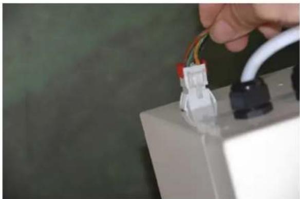
natural_image
Close-up of a hand holding a white cable with multiple wires connected to a battery block (no visible text or symbols)+: Hold inne for å stille inn timer TIME
+: Hold inne for å stille inn timer. TIME
natural_image
Technical line drawing of a mechanical assembly showing internal components and housing (no text or symbols)Vannpumpe
• Elektriske data: 230 VAC +10 %/-6 %, 50 Hz, 1-fase.
• Maks. systemtrykk: 1,0 MPa.
line
| Label | Value | |-------|-------| | AUTO | High | | HD2 | Medium| | HD1 | Low | | BL2 | Medium| | BL1 | Low |natural_image
Collection of construction tools laid out on concrete ground, including a metal ruler, wrenches, pliers, and hydraulic wrenches (no text or symbols visible)natural_image
Isometric line drawing of a rectangular box with a black stripe and two small buttons at the bottom (no text or symbols)
Utedel
natural_image
Close-up of a mechanical piping assembly with copper and brass fittings, mounted on a white electrical panel (no visible text or symbols)
natural_image
White metal frame structure on a concrete floor with scattered plastic and plastic bags (no text or symbols visible)Installasjonssett
natural_image
Assorted automotive components including hoses, tires, and sensors (no visible text or labels)Hull
natural_image
Person using a red power drill on a tiled wall (no text or symbols visible)natural_image
Person standing beside a white metal frame structure against a tiled wall (no text or symbols visible)natural_image
Person holding a large air conditioner unit mounted on a wall, no visible text or symbols
natural_image
Close-up of hands installing or adjusting a white metal component on a tiled wall (no text or symbols visible)
natural_image
Pure mechanical joint diagram without any text, numbers, or symbolsnatural_image
Close-up of hands holding two black mechanical parts, no visible text or symbolsnatural_image
Close-up of hands using a pliers to adjust a copper pipe fitting with a brass fitting (no visible text or symbols)VIKTIG!
natural_image
Simple circular diagram with diameter and radius arrows, no text or symbols presentnatural_image
Hand inserting a small electronic device into a white electrical box (no visible text or symbols)natural_image
Close-up of hands using pliers to adjust a copper pipe fitting (no text or symbols visible)natural_image
Close-up of hands using pliers to adjust or install a mechanical component with brass fittings (no visible text or symbols)natural_image
Close-up of a hand inserting wires into an electrical enclosure (no visible text or symbols)
natural_image
Close-up of a hand holding wires connected to a battery pack (no visible text or symbols)natural_image
Technical line drawing of a mechanical component with exploded view, showing internal structure and mounting holes (no text or symbols)Pompa wodna
line
| Label | Value | |-------|-------| | AUTO | High | | HD2 | Medium| | HD1 | Low | | BL2 | Medium| | BL1 | Low |natural_image
Collection of construction tools laid out on concrete ground, including a metal ruler, wrenches, pliers, and hydraulic wrenches (no text or symbols visible)natural_image
Isometric line drawing of a rectangular box with a black stripe and two small buttons at the bottom (no text or symbols)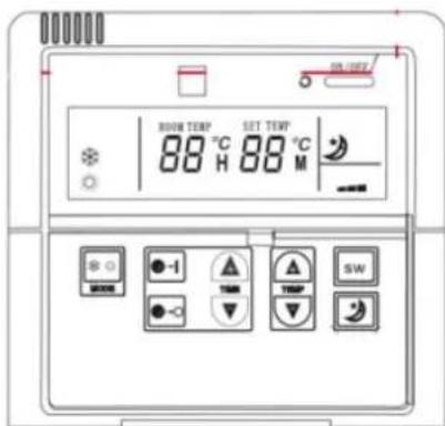
natural_image
Close-up of a mechanical piping assembly with copper and brass fittings, mounted on a white electrical panel (no visible text or symbols)
natural_image
White metal L-shaped structure with two legs and a small plastic bag placed on the ground (no text or symbols visible)Zestaw instalacyjny
natural_image
Assorted automotive components including hoses, tires, and sensors (no visible text or labels)Otwory
natural_image
Person using a red power drill on a tiled wall (no text or symbols visible)natural_image
Person standing beside a white metal frame structure against a tiled wall (no text or symbols visible)natural_image
Person holding a wall-mounted air conditioner unit with solar panels, next to a tiled wall (no visible text or symbols)
natural_image
Close-up of hands installing or adjusting a white architectural panel on a tiled wall (no text or symbols visible)
Montaż rur i kabli
natural_image
Pure technical line drawing of a mechanical joint or bracket (no text or symbols)natural_image
Close-up of hands holding a black and gold object, possibly a lipstick or mechanical component (no visible text or symbols)natural_image
Close-up of hands using pliers to adjust a copper pipe fitting with a brass fitting (no visible text or symbols)WAŻNE!
natural_image
Simple circular diagram with diameter and radius arrows, no text or symbols presentnatural_image
Close-up of a hand adjusting a yellow electrical socket mounted on a white electrical cabinet (no visible text or symbols)natural_image
Close-up of hands using pliers to adjust a copper pipe fitting (no text or symbols visible)natural_image
Close-up of hands using a tool to adjust or install a mechanical component, no visible text or symbolsnatural_image
Close-up of a hand inserting wires into an electrical enclosure (no visible text or symbols)
natural_image
Close-up of a hand holding wires connected to a battery pack (no visible text or symbols)Read the Operating Instructions carefully before use.
Save these instructions for future reference.
Electrical safety
New installations and the expansion of existing systems may only be performed by a qualified electrician. Individuals with sufficient knowledge may replace switches and wall sockets, fit plugs, extension cords and lamp bases. Contact an electrician if in doubt. Incorrect installation can cause a fire or electric shock.
General
• Connection to a water pipe system may only be performed by an authorised plumbing engineer.
• Refrigerant pipes must not be bent to a radius of less than 15 cm.
- Do not connect the appliance to the mains supply until the pipes have been connected, the system modules have been connected together and the system has been filled with water and vented.
- The units are heavy and have sharp edges. Lift the units with the correct lifting technique. Wear safety gloves and safety glasses.
- Only remove the plastic plugs from the pipe ends immediately before the pipes are to be connected.
- Check and tighten the connections after 24 hours. The refrigerant connections must be tightened to 18 Nm. Use a torque wrench if in doubt. Make sure that the indoor unit and outdoor unit have the same model designation.
IMPORTANT:
- The appliance is not intended to be used by persons (children or adults) with any form of functional disorders, or by persons who do not have sufficient experience or knowledge on how to use it, unless they have received instructions concerning the use of the appliance from someone who is responsible for their safety. Keep children under supervision to make sure they do not play with the appliance.
- A damaged power cord must be replaced by an authorised service centre, or qualified person, to ensure safe use.
- The appliance uses environmentally-friendly R410A refrigerant, which is among the most energy-efficient on the market. The compressor is frequency converter-controlled, which produces a higher level of efficiency.
- The system monitors the socket and the frequency converter continually adapts the compressor speed as required to achieve optimum energy efficiency.
• The control system's microprocessor and software deliver optimum operation under all conditions. - Vibration-damping mounts and bushings ensure quiet operation.
- Status indicator lamps make it easy to monitor the appliance.
- Soft-start function for the compressor.
• Night reduction function ensures extra quiet operation during the night.
• After a power cut, the appliance restarts automatically with the former settings. - Connect the appliance to a separate electrical circuit (230 VAC, 50 Hz) with a 10 A fuse, overvoltage protection and residual current device. Only connect the appliance to a correctly earthed mains supply.
- The outdoor unit is supplied with a pre-heater and heating coil for operation at low outdoor temperatures. This reduces wear and provides a longer service life for the compressor, as well as facilitating drainage during defrosting. The functions are regulated electronically based on the outdoor temperature.
- The defrost system is activated automatically and defrosts the appliance at suitable intervals, depending on the outdoor temperature.
- Timer function for turning on and off.
• The outdoor unit has acrylic-coated aluminium fins for optimum run-off and corrosion protection. - The heat exchanger is manufactured in accordance with the latest technology, with a large surface for optimum heat transfer.
-
Select the correct appliance size. The heat pump normally covers around 50% of the energy requirement for heating, and can be connected to existing systems.
-
The heat pumps draws energy from the outside air. The efficiency decreases when the outdoor temperature drops. It is therefore necessary to have additional energy from your existing heating system when it gets colder outside.
- The maximum permitted water temperature is 50^ C, while the maximum recommended operating temperature is 45^ C. Note that the appliance cannot reach maximum temperature without additional energy in the event of a very large energy output or when it is cold outside.
- Note that the heat pump in normal operation can raise the water temperature by between 2 and 5°C, depending on the outdoor temperature.
- In the event of any interference or if an error code is displayed, turn off the appliance, wait for 5 minutes and start the appliance again.
TECHNICAL DATA
Max. output, heating 6000 W
Max. output, cooling 4600 W
Power consumption, complete unit – 500-1750 W heating
Power consumption, complete unit – 495-1650 W cooling
Nominal output, heating 1400-5270 W
Operating temperature -25 to 40°C
Max. water flow 3.5 m3/h
Defrosting Yes
Heating coil for defrosting Yes
Compressor pre-heating Yes
Compressor Frequency converter-controlled, rotating
Noise level, indoor unit 35 dB
Noise level, outdoor unit 52 dB
Weight, indoor unit 22 kg
Weight, outdoor unit 33 kg
Refrigerant R410A
Dimensions, indoor unit (w x h x d) 450 x 195 x 570 mm
Dimensions, outdoor unit (w x h x d) 780 x 255 x 550 mm
Electrical data* 230 VAC, 50 Hz, 10 A, earthed connection Residual current device and Required
overvoltage protection
* Slow fuse
DESCRIPTION
Indoor unit
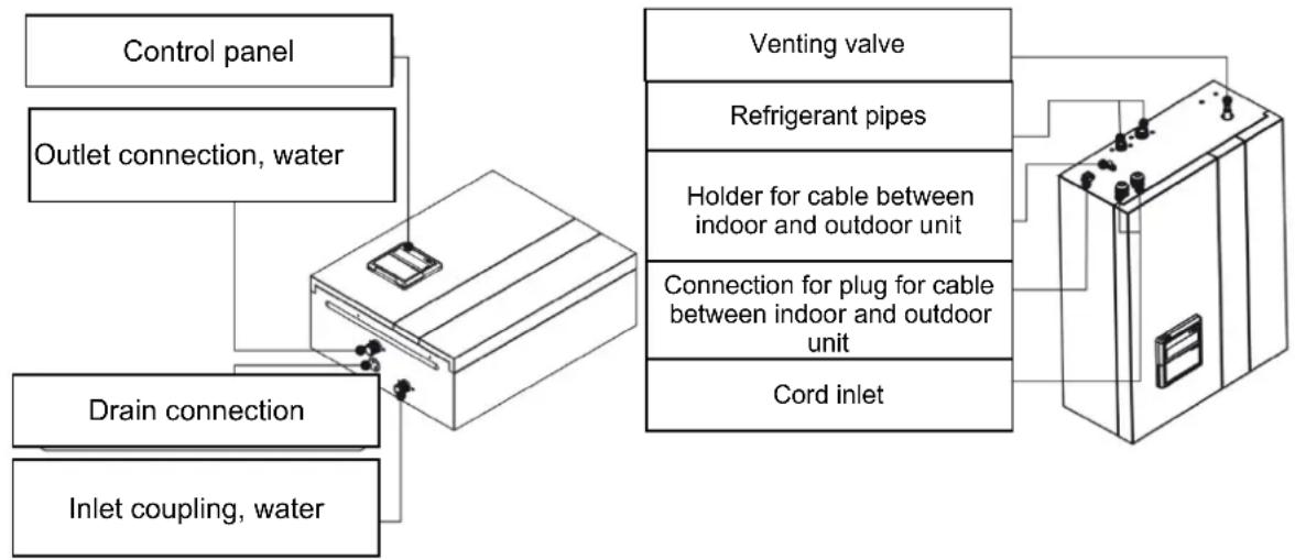
flowchart
graph TD
    A["Control panel"] --> B["Outlet connection, water"]
    B --> C["Drain connection"]
    C --> D["Inlet coupling, water"]
    E["Venting valve"] --> F["Refrigerant pipes"]
    F --> G["Holder for cable between indoor and outdoor unit"]
    G --> H["Connection for plug for cable between indoor and outdoor unit"]
    H --> I["Cord inlet"]
    I --> J["Electrical unit"]
Outdoor unit

Control panel

OPERATION
On/Off
Start and stop the appliance with the ON/OFF button.
The active operating mode is indicated with or .


Operating modes
Press the MODE button to select the operating mode.
- Press the MODE button repeatedly to browse to the desired operating mode in the order set out below.
- Cooling
- Heating
Standard settings for temperature
Cooling: 22°C.
Heating: 26°C.
Temperature +
In cooling or heating mode:
- : increases the setpoint temperature by 1°C TEMP
• : decreases the setpoint temperature by 1°C
Press the SW button to select regulation according to room temperature or regulation according to ingoing water temperature.
The status lamp flashes in the event of regulation according to ingoing water temperature, and shines steadily in the event of regulation according to the room temperature in the room where the control panel is located.
Timer/night reduction
Starting
- Press the button to set the start time for the appliance.
- Set the hours and minutes until the appliance is to start (not clock time).
+: keep pressed to set hours
TIME
▼: press to set the minutes
The first time set is the start time.
NOTE: The clock as a 24-hour display.
Stopping
- Press the button to set the power-off time for the appliance.
- Set the hours and minutes until the appliance is to be switched off (not clock time).
+: Keep pressed to set hours.
TIME
: Press to set the minutes. The second time set is the stop time. NOTE: The clock as a 24-hour display.
Night reduction

Activate/deactivate night reduction with the button.
- In cooling mode, the setpoint temperature is raised by 3^ .
- In heating mode, the setpoint temperature is lowered by 4^ .
Night reduction is deactivated automatically after 8 hours and the appliance returns to normal operation.
Electric heater
The electric heater provides additional heating in the event of a low outdoor temperature, when the appliance is not delivering sufficient heating. The electric heater is activated automatically in the following conditions.
- Ambient temperature lower than 10^ .
- The compressor has been working continuously for 25 minutes.
• The compressor is operating at maximum speed. - The water temperature is 3^ lower than the setpoint temperature.
• The water temperature rises by less than 1°C in 15 minutes.
- The room temperature rises by less than 1^ in 15 minutes.
• The mechanical thermostat's set temperature is higher than that of the heat pump.
- The electric heater can be activated manually in the event of faults in other heat sources. Set the water temperature manually.
- The electric heater can be used to heat the water in the system to 70°C to counteract bacterial growth.
- If the heat pump does not work, set the selector to MT mode (electric heater controlled by the mechanical thermostat) and set the setpoint temperature with the knob.

NOTE: Disconnect the power supply before working on electrical components.
Troubleshooting
NOTE: Disconnect the power supply to the appliance before carrying out maintenance.
Contact your dealer or another qualified person if you cannot resolve the problem on the basis of the list below.
- Check that the power supply is working.
- Check that there is no wire breakage in the electric heater.
- Check whether too low water temperature has been set.
- Check that the controller is working.
- Check that lime has not been deposited on the heater element.
Removing lime deposits
- Disconnect the power supply.
- Undo the screws holding the electric heater and remove the electrical cable and the heater element from the cylinder.
- Clean the heater element with a hard brush. If necessary use vinegar in the event of significant deposits.
- Replace the heater element and the electrical cable in the cylinder and replace the screws.

natural_image
Technical line drawing of a mechanical component with exploded view, showing internal structure and mounting holes (no text or symbols)Water pump
• Electrical data: 230 VAC +10%/-6%, 50 Hz, 1-phase.
• Max. system pressure: 1.0 MPa.
• The following inlet pressure must exist in order to avoid damage as a result of cavitation.
| Liquid temperature 85°C | 90°C 110°C | ||
| Inlet pressure 0.50 bar 0.28 | bar 1.00 bar | ||
| Lifting height 0.5 m Lifting | height 3.0 m Lifting height | 10 m |
- Operating temperature: 0 to 40°C. Relative air humidity: < 95%. Water temperature: 2 to 110°C. The ambient temperature must be lower than the water temperature, as otherwise there is a risk of condensation in the stator.
- The pump is intended for the circulation of liquid that is clean, non-corrosive and non-explosive, with no solid particles, fibres or mineral oil. The pump must not be used to pump flammable liquids such as vegetable oil, petrol or the like. The pump capacity is affected by the viscosity of the liquid, which must be taken into consideration during dimensioning.
- The water pump is lubricated by the pumped liquid. Do not start the pump until the system has been filled with liquid.
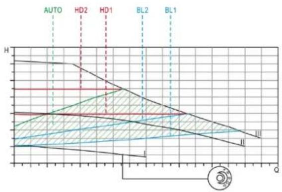
Capacity curve

line
| Q(m³/h) | H(m) HD1 | H(m) HD2 | H(m) AUTO | H(m) BL1 | H(m) BL2 | P1(W) HD1 | P1(W) HD2 | P1(W) AUTO | P1(W) BL2 | P1(W) III | |---------|----------|----------|-----------|----------|----------|-----------|-----------|------------|-----------|-----------| | 0.0 | 3.0 | 4.5 | 1.0 | 1.0 | 1.0 | 15.0 | 20.0 | 10.0 | 5.0 | 35.0 | | 0.2 | 3.0 | 4.5 | 1.0 | 1.0 | 1.0 | 18.0 | 22.0 | 12.0 | 7.0 | 40.0 | | 0.4 | 3.0 | 4.5 | 1.0 | 1.0 | 1.0 | 20.0 | 25.0 | 15.0 | 9.0 | 45.0 | | 0.6 | 3.0 | 4.5 | 1.0 | 1.0 | 1.0 | 22.0 | 28.0 | 18.0 | 11.0 | 50.0 | | 0.8 | 3.0 | 4.5 | 1.0 | 1.0 | 1.0 | 24.0 | 30.0 | 20.0 | 13.0 | 55.0 | | 1.0 | 3.0 | 4.5 | 1.0 | 1.0 | 1.0 | 26.0 | 32.0 | 22.0 | 15.0 | 60.0 | | 1.2 | 3.0 | 4.5 | 1.0 | 1.0 | 1.0 | 28.0 | 34.0 | 24.0 | 17.0 | 65.0 | | 1.4 | 3.0 | 4.5 | 1.0 | 1.0 | 1.0 | 30.0 | 36.0 | 26.0 | 19.0 | 70.0 | | 1.6 | 3.0 | 4.5 | 1.0 | 1.0 | 1.0 | 32.0 | 38.0 | 28.0 | 21.0 | 75.0 | | 1.8 | 3.0 | 4.5 | 1.0 | 1.0 | 1.0 | 34.0 | 40.0 | 30.0 | 23.0 | 80.0 | | 2.0 | 3.0 | 4.5 | 1.0 | 1.0 | 1.0 | 36.0 | 42.0 | 32.0 | 25.0 | 85.0 | | 2.2 | 3.0 | 4.5 | 1.0 | 1.0 | 1.0 | 38.0 | 44.0 | 34.0 | 27.0 | 90.0 | | 2.4 | 3.0 | 4.5 | 1.0 | 1.0 | 1.0 | 40.0 | 46.0 | 36.0 | 29.0 | 95.0 | | 2.6 | 3.0 | 4.5 | 1.0 | 1.0 | 1.0 | 42.0 | 48.0 | 38.0 | 31.0 | 100.0 | | 2.8 | 3.0 | 4.5 | 1.0 | 1.0 | 1.0 | 44.0 | 50.0 | 40.0 | 33.0 | | | 3.0 | | | | | | | | | | |Regulation

line
| Label | Value | |-------|-------| | AUTO | High | | HD2 | Medium| | HD1 | Low | | BL2 | Medium| | BL1 | Low || Adjusting Capacity curve Function | ||
| Factory setting The | proportional pressure curve that goes from the highest to the lowest operating point. | The Autoadapt function automatically controls pump capacity within the specified capacity range. (1) The pump capacity is adapted to the size of the system. (2) The pump capacity is adapted to the load history of the system. Autoadapt uses proportional pressure regulation. |
| BL1 Lower proportional pressure curve | The operating point follows the lower proportional pressure curve, depending on the heating requirement. The pump pressure drops in the event of a decreasing heating requirement and rises in the event of an increasing heating requirement. | |
| BL2 Upper proportional pressure curve | The operating point follows the upper proportional pressure curve, depending on the heating requirement. The pump pressure drops in the event of a decreasing heating requirement and rises in the event of an increasing heating requirement. | |
| HD1 Lower constant pressure curve | The operating point follows the lower constant pressure curve, depending on the heating requirement. The pump ressure remains constant, irrespective of the flow. | |
| HD2 Upper constant pressure curve | The operating point follows the upper constant pressure curve, depending on the heating requirement. The pump ressure remains constant, irrespective of the flow. | |
| III | Speed III | The pump works on the constant curve with a fixed speed. At speed III, the pump works constantly on the upper constant curve. The pump can be run temporarily at speed III to be bled. |
| II | Speed II | The pump works on the constant curve with a fixed speed. At speed II, the pump works constantly on the central constant curve. |
| I | Speed I | The pump works on the constant curve with a fixed speed. At speed I, the pump works constantly on the lower constant curve. |
 | [BYH7] | In night reduction mode, the pump automatically works with a lower capacity and energy consumption. |
INSTALLATION TYPES
Heater with double casing

flowchart
graph TD
    A["Outdoor unit"] --> B["Indoor unit"]
    B --> C["Incoming cold water"]
    C --> D["Outgoing hot water"]
    D --> E["Existing boiler or hot water tank"]
    E --> F["Expansion vessel"]
    F --> G["Venting valve"]
    G --> H["Relief valve"]
    H --> I["Supply line Return"]
    I --> J["Underfloor heating"]
    J --> K["Filter"]
    K --> L["You can connect a separate hot water tank to the air/water heat pump and thereby allow the appliance to heat the domestic hot water."]
Direct connection to waterborne heating system
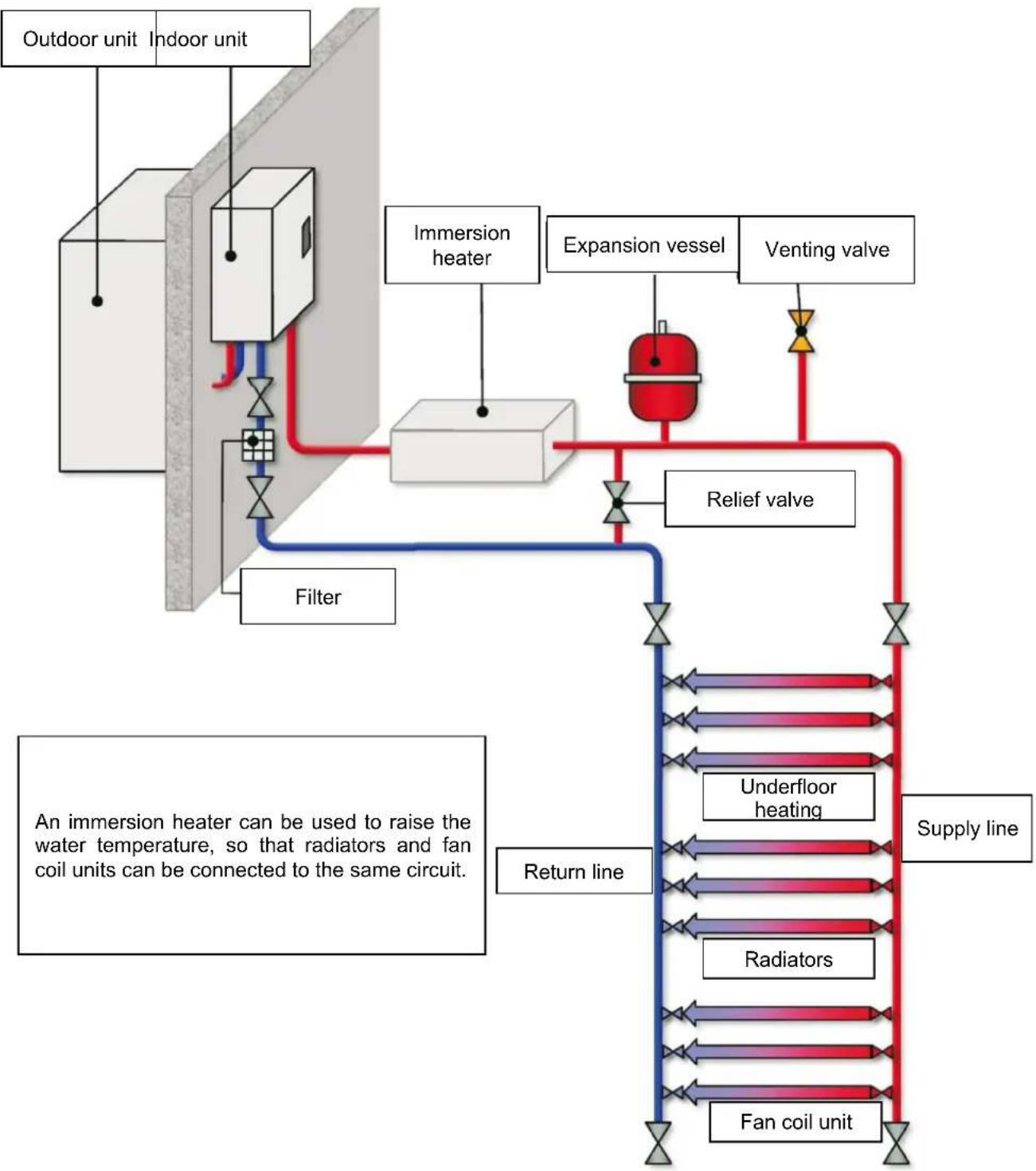
flowchart
graph TD
    A["Outdoor unit"] --> B["Indoor unit"]
    B --> C["Immersion heater"]
    C --> D["Expansion vessel"]
    D --> E["Venting valve"]
    E --> F["Relief valve"]
    F --> G["Return line"]
    G --> H["Underfloor heating"]
    H --> I["Supply line"]
    I --> J["Radiators"]
    J --> K["Fan coil unit"]
    K --> L["Filter"]
    L --> M["Adder/Transfer to Outdoor Unit"]
    style A fill:#f9f,stroke:#333
    style B fill:#f9f,stroke:#333
    style C fill:#ccf,stroke:#333
    style D fill:#cfc,stroke:#333
    style E fill:#fcc,stroke:#333
    style F fill:#cff,stroke:#333
    style G fill:#ffc,stroke:#333
    style H fill:#cfc,stroke:#333
    style I fill:#fcc,stroke:#333
    style J fill:#cfc,stroke:#333
    style K fill:#cfc,stroke:#333
    style L fill:#fcc,stroke:#333
    style M fill:#ffc,stroke:#333
Heat source with shunt
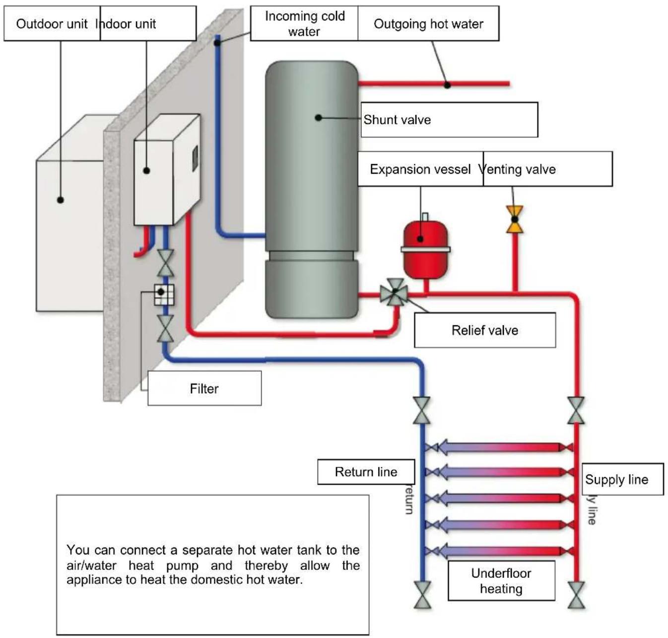
flowchart
graph TD
    A["Outdoor unit"] --> B["Indoor unit"]
    B --> C["Incoming cold water"]
    C --> D["Shunt valve"]
    C --> E["Venting valve"]
    D --> F["Expansion vessel"]
    E --> F
    F --> G["Relief valve"]
    G --> H["Supply line y line"]
    H --> I["Underfloor heating"]
    I --> J["Return line return"]
    J --> K["Filter"]
    K --> L["Outdoor unit"]
    style A fill:#f9f,stroke:#333
    style B fill:#f9f,stroke:#333
    style C fill:#ccc,stroke:#333
    style D fill:#fff,stroke:#333
    style E fill:#fff,stroke:#333
    style F fill:#fff,stroke:#333
    style G fill:#fff,stroke:#333
    style H fill:#fff,stroke:#333
    style I fill:#fff,stroke:#333
    style J fill:#fff,stroke:#333
    style K fill:#fff,stroke:#333
    style L fill:#fff,stroke:#333
Multifunction tank
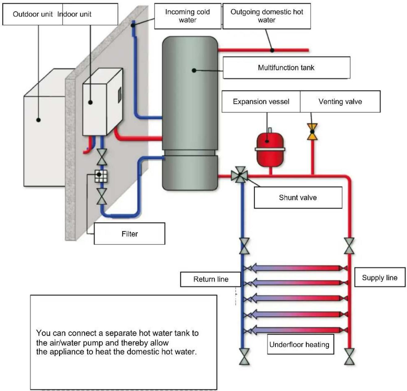
flowchart
graph TD
    A["Outdoor unit"] --> B["Indoor unit"]
    B --> C["Filter"]
    C --> D["Incoming cold water"]
    D --> E["Shunt valve"]
    E --> F["Supply line"]
    F --> G["Return line"]
    G --> H["Underfloor heating"]
    H --> I["Venting valve"]
    I --> J["Expansion vessel"]
    J --> K["Multifunction tank"]
    K --> L["Outgoing domestic hot water"]
    style A fill:#f9f,stroke:#333
    style B fill:#f9f,stroke:#333
    style C fill:#ccf,stroke:#333
    style D fill:#cff,stroke:#333
    style E fill:#ffc,stroke:#333
    style F fill:#cfc,stroke:#333
    style G fill:#fcc,stroke:#333
    style H fill:#fcc,stroke:#333
    style I fill:#fcc,stroke:#333
    style J fill:#fcc,stroke:#333
    style K fill:#fcc,stroke:#333
    style L fill:#fcc,stroke:#333
    style_M["You can connect a separate hot water tank to the air/water pump and thereby allow the appliance to heat the domestic hot water."]
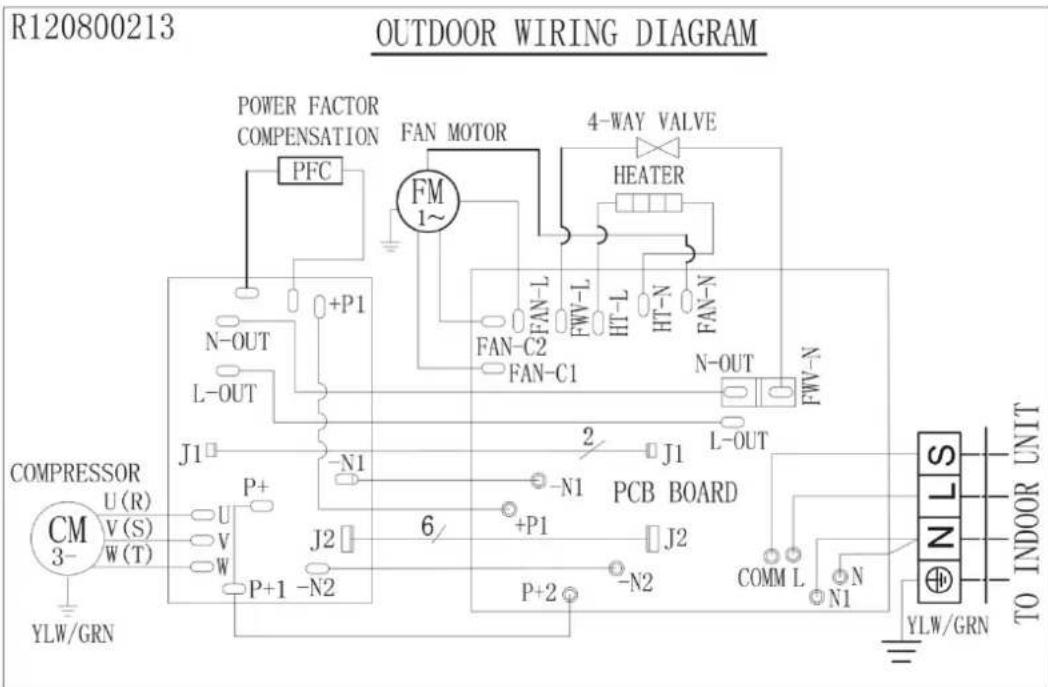
WIRING DIAGRAM

NOTE: Parts within dashed lines are only present on certain models.
INSTALLATION
Checklist when positioning the indoor and outdoor units
- The indoor unit must be placed indoors.
- If possible, the indoor unit should be positioned on the inside of the outer wall, in order to minimise the amount of visible piping.
- When choosing the installation point, remember that the appliance's rotating parts generate some sound and can cause resonance.
- Check that the walls at the installation points can cope with the weight of the indoor and outdoor units. Reinforce the walls, if necessary.
- Do not allow uninsulated refrigerant pipes form the indoor unit to come into contact with the wall – condensation that forms on the pipes can damage the wall and floor. Use the insulation in the enclosed installation kit.
- We recommend that the outdoor unit should not be installed on a wooden wall. Install vibration dampers between the unit and the wall brackets.
- If it is not possible to install the outdoor unit on the house wall, we recommend that it is located on a concrete block or stand.
• If the outdoor unit is exposed to wind, it must be secured with a metal frame and screw.
IMPORTANT:
- Check that are no electrical cables, gas and/or water pipes in the installation area.
- Do not position the outdoor unit close to bedroom windows, if this can be avoided.
- Position the outdoor unit where it does not disturb the surroundings and provide it with protection if possible.
Module system
The module system from Anslut consists of pre-filled pipes and units. The system is pre-filled and vented. Do not subject the spring-loaded shut-off valves in the connections to mechanical stress – risk of refrigerant leaks. Save the protective plugs until all the connections have been made. The patented installation system with pre-filled modules is much easier to install than traditional systems. This provides low installation costs for Anslut air heat pumps.
Note that these installation instructions are for guidance, and may deviate from the actual installation. Check the actual system and follow applicable rules during installation.
Tools needed
Spirit level, pencil, crosshead screwdriver, 8 mm masonry drill bit, pilot drill, set-square, tape measure or folding rule, 65 mm wide tape, hole saw approx. 80 mm (actual dimension can vary), knife, two adjustable spanners and possibly a torque wrench.

natural_image
Collection of various hand tools laid out on a concrete floor, including pliers, wrenches, and a measuring tool (no text or symbols visible)Indoor unit and control panel
We recommend that the indoor unit be installed in or close to the boiler room. Ask a plumbing engineer for advice regarding the optimum location in relation to the existing heating system. We recommend the use of flexible hoses for connection of the indoor unit. The control panel can be located anywhere in the building. If the unit is to be used for regulating according to room temperature, the control panel should be located in the room where maintaining the correct temperature is most important.

natural_image
Isometric line drawing of a rectangular electronic device with a black tab and two ports (no text or symbols)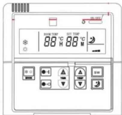
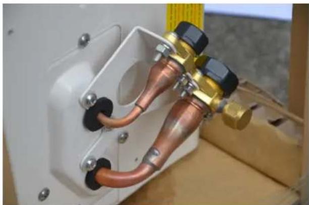
Outdoor unit
The outdoor unit has 2 wall brackets, 4 vibration dampers and mounting screws for masonry/concrete walls. The outdoor unit's pipe sections are pre-filled and supplied with screw connections with non-return valves.
natural_image
Close-up of a mechanical piping assembly with copper and brass fittings, mounted on a white electrical panel (no visible text or symbols)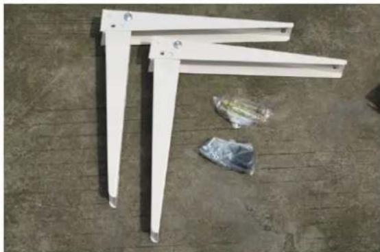
natural_image
White metal L-shaped structural frame with two legs and a small plastic bag placed on the floor (no text or symbols visible)Installation kit
The installation kit comprises 2 gas-filled pipes, drainage hose, sealing compound, polyethylene tape, 2 insulation sections, cable ties and electrical cable with connections for the indoor and the outdoor unit. Note that the drainage hose is only used for air/air-heat pumps, not for air/water-heat pumps.
NOTE: Do not remove the plastic plugs from the pipe ends before commencing installation.

natural_image
Assorted automotive components including hoses, tires, and sensors (no visible text or labels)Hole
- First drill with the pilot drill to check that the area is free from obstacles and that the hole is correctly positioned. Move the pilot drill within the wall to determine whether there are any obstacles close to the hole.
- If there are no obstacles, install the wall bracket and make the bushing hole (approx. 80 mm, depending on the enclosed wall bushing) with a hole saw.
- Use a low speed to avoid overheating. Feel free to pre-drill with a 12–15 mm drill bit for better swarf management.

natural_image
Person using a red drill putting or drawing on a tiled wall (no text or symbols visible)
natural_image
Person using a red power drill on a tiled wall (no text or symbols visible)Location of the outdoor unit
Position the outdoor unit in a location that enjoys good ventilation, not inside a building, carport or similar. Leave at least 4 m of free space in front of the outdoor unit and at least 10 cm between the wall and the rear of the outdoor unit. Remember that water will run from the outdoor unit during defrosting. The heating coil in the bottom tray means that the water will not freeze in the unit, although ice can form on the ground under the unit.
Brackets
The enclosed brackets are intended for installation on walls made of brick, concrete or similar. When installing on a wooden wall, suitable reinforcement and assembly components must be used. We recommended that ground stands be used rather than installing on a wooden wall. Install the brackets with a c/c distance of 505 mm (does not apply to 416-086), at least 50 cm above the ground. In snowy areas, the unit should be located higher up, to ensure good air circulation and drainage.

natural_image
Person standing beside a white metal frame structure against a tiled wall (no text or symbols visible)Installation of outdoor unit
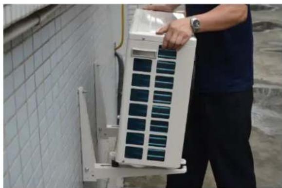
Place the unit on the wall brackets with vibration dampers in between. Do not tighten the nuts so hard that the rubber is compressed, as this impairs the vibration attenuation. Leave at least 10 cm of free space between the wall and the rear of the unit to ensure the correct air circulation.
NOTE: Check that the outdoor unit is horizontal. It is particularly important that the outdoor unit does not lean forward too much, or to the right. Adjust with spacers, if necessary.
natural_image
Person holding a white air conditioner unit with blue solar panels, standing beside a tiled wall (no visible text or symbols)
natural_image
Close-up of hands installing or adjusting a white wall component against a tiled wall (no text or symbols visible)
Pipe and cable routing
When the outdoor and indoor units have been installed, it is time to install refrigerant pipes and electrical cables between them. Remove the lower part of the indoor unit to facilitate installation (does not apply to 416-086). The electrical cable with 4 conductors has a plug for simple connection to the indoor unit. Insert the plug in the connection and secure the cable in the holder. Never connect the power supply to the appliance before the pipelines have been installed and the system modules have been connected together. Press the wall bushing into the hole from the outside, then press on and lock the cover ring.

natural_image
Pure technical line drawing of a mechanical joint or bracket (no text or symbols)Routing refrigerant pipes
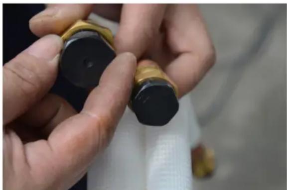
Begin routing from the indoor unit and straighten out the pipes as you go. On the pipe ends in the installation kit are cap nuts for connection to the fixed pipe sections on the units. The cap nuts cannot be installed incorrectly. Hold the connection in place with one spanner and tighten the cap nut with the other, as otherwise the connection can be damaged.
natural_image
Close-up of hands holding a black and gold object, possibly a lipstick or mechanical component (no visible text or symbols)Connect the installation kit's pipes to the connections on the indoor unit. First screw together the screw connections by hand and then tighten using the spanners. Tighten the connection fully without stopping. A hissing noise can be heard. Hold the connection in place with one spanner and tighten the cap nut with the other.
Tighten to at least 18 Nm. Use a torque wrench if you are unsure.
Never turn the fixed connections. Use the spanner only as a counterhold during connection.
If a counterhold is not used, the connections can turn, which can destroy them. Tighten the connections 24 hours after installation has been completed.

natural_image
Close-up of hands using pliers to adjust a brass pipe fitting (no text or symbols visible)IMPORTANT:
The pipes in the installation kit are filled with gas and must not be cut under any circumstances. Do not remove the plastic plugs from the pipe ends until the pipes are to be connected. If the pipes are deformed and are causing leaks, disconnect the cap nuts from the connections so that the non-return valves close.
Pipe routing
IMPORTANT:
Route the pipes from the indoor unit to the outdoor unit and connect them in the same way to the outdoor unit. Refrigerant pipes must not be bent to a radius of less than 15 cm (check with a cardboard template). Route the electrical cable along the pipes. Bend the pipes carefully, a little at a time. Do not bend the pipes too sharply.
Radius 15 cm

natural_image
Simple circular diagram with diameter lines and a double-headed arrow, no text or symbols presentConnecting the installation kit
- On the pipe ends in the installation kit are cap nuts for connection to the fixed pipe sections on the outdoor unit.
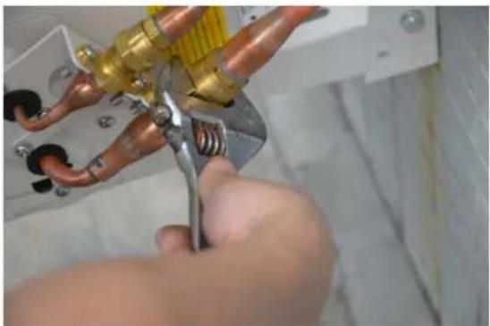
- The cap nuts cannot be installed incorrectly. Hold the connection in place with one spanner and tighten the cap nut with the other, as otherwise the connection can be damaged.
- Connect the installation kit's pipes to the connections on the outdoor unit. First screw together the screw connections by hand and then tighten using the spanners.

natural_image
Hand inserting a small electronic device into a white electrical box (no visible text or symbols)- Tighten the connection fully without stopping. A hissing noise can be heard. Hold the connection in place with one spanner and tighten the cap nut with the other.
- Never turn the fixed connections. Use the spanner only as a counterhold during connection. If a counterhold is not used, the connections can turn, which can destroy them. Tigthen the connections 24 hours after installation has been completed.
natural_image
Close-up of hands using pliers to adjust a copper pipe fitting (no text or symbols visible)- Check the connections for leaks by applying soapy water on them and looking for bubbles.
- Repeat the leak test using soapy water on all connections after 24 hours.

natural_image
Close-up of hands using a tool to adjust or install a mechanical component, no visible text or symbolsElectrical connection, indoor unit
IMPORTANT:
Never connect the power supply to the appliance unit the following connections have been made and the protection has been replaced. The appliance is connected to electricity with a power cord, which is why no work needs to be performed in the building's electrical system.
Electrical connection, outdoor unit
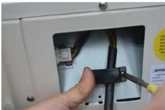
Unscrew and remove the cover over the outdoor unit's connection box. Insert the plug in the connection and secure the cable in the holder.

natural_image
Close-up of a hand inserting wires into an electrical enclosure (no visible text or symbols)
natural_image
Close-up of a hand holding wires connected to a battery pack (no visible text or symbols)Jula reserves the right to make changes. In the event of problems, please contact our service department.
www.jula.com
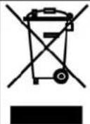
Care for the environment!
Must not be discarded with household waste! This product contains electrical or electronic components that should be recycled. Leave the product for recycling at the designated station e.g. the local authority's recycling station.
- Operating Instructions for Heat pump air/water
- SVENSKA 5
- SÄKERHETSANVISNINGAR 5
- TEKNISKA DATA 6
- BESKRIVNING 6
- HANDHAVANDE 8
- SÄKERHETSANVISNINGAR
- Vattenpump
- Utomhusenhet
- Installationssats
- Hål
- VIKTIGT!
- Vannpumpe
- Utedel
- Installasjonssett
- Hull
- VIKTIG!
- Pompa wodna
- Zestaw instalacyjny
- Otwory
- Montaż rur i kabli
- WAŻNE!
- Read the Operating Instructions carefully before use.
- Electrical safety
- General
- IMPORTANT:
- TECHNICAL DATA
- DESCRIPTION
- Indoor unit
- OPERATION
- On/Off
- Operating modes
- Temperature +
- Timer/night reduction
- Starting
- Stopping
- Night reduction
- Electric heater
- Troubleshooting
- Removing lime deposits
- Water pump
- INSTALLATION TYPES
- WIRING DIAGRAM
- INSTALLATION
- Checklist when positioning the indoor and outdoor units
- Module system
- Tools needed
- Indoor unit and control panel
- Outdoor unit
- Installation kit
- Hole
- Location of the outdoor unit
- Brackets
- Installation of outdoor unit
- Pipe and cable routing
- Routing refrigerant pipes
- Pipe routing
- Connecting the installation kit
- Electrical connection, indoor unit
- Electrical connection, outdoor unit
- Care for the environment!
Brand : Anslut
Model : 416-107
Category : Air conditioner