007-018 - Air conditioner Anslut - Free user manual and instructions
Find the device manual for free 007-018 Anslut in PDF.


| Product Type | Portable Air Conditioner |
| Brand | Anslut |
| Model | 007-018 |
| Dimensions (H x W x D) | 700 x 350 x 360 mm |
| Weight | 23.5 kg |
| Rated Voltage | 230 V ~ 50 Hz |
| Power Consumption | 1100 W |
| Cooling Capacity | 2300 W / 8000 BTU/h |
| Dehumidifying Capacity | 2.1 L/h |
| Refrigerant | R290A (flammable) |
| Energy Class | A |
| Noise Level | 65 dB |
| Temperature Range (Cooling) | 17–35 °C |
| Current | 4.1 A |
| Power Cord Length | 1.5 m |
| Remote Control | Included, range 8 m, 2x R03 batteries |
| Operating Modes | Cool, Fan, Dry, Auto |
| Timer | 24-hour programmable on/off |
| Display | LED temperature display |
| Air Filter | Washable, clean every 2 weeks |
| Drain Method | Continuous drainage or manual tank emptying (P1 warning) |
| Wheels | Yes, for easy mobility |
| Safety Features | Auto restart, 3-minute delay, overheat protection, child lock |
| Window Kit Included | Yes, for vertical/horizontal sliding windows or wall mount |
| Refrigerant Type | R290A (flammable) |
Frequently Asked Questions - 007-018 Anslut
User questions about 007-018 Anslut
0 question about this device. Answer the ones you know or ask your own.
Ask a new question about this device
Download the instructions for your Air conditioner in PDF format for free! Find your manual 007-018 - Anslut and take your electronic device back in hand. On this page are published all the documents necessary for the use of your device. 007-018 by Anslut.
USER MANUAL 007-018 Anslut
natural_image
White industrial air conditioner unit with ventilation slots and a black lid (no visible text or symbols)
SE LUFTKONDITIONERING
Operating instructions (Translation of the original instructions) Important! Read the user instructions carefully before use. Save them for future reference.
Värna om miljön!
Care for the environment!
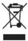
Must not be discarded with household waste! This product contains electrical or electronic components that should be recycled. Leave the product for recycling at the designated station e.g. the local authority's recycling station.
Jula reserves the right to make changes. In the event of problems, please contact our service department.
www.jula.com
Tillverkare/ Produsent/ Producenci/ Manufacturer
Jula AB, Box 363, 532 24 SKARA
Distributör/ Distributør/ Dystrybutor/ Distributor
Jula Poland Sp. z o.o., ul.
 | A |
 | B |
 | C |
 | D |
 | E |
 | F |
 | G |
 | H |
 4 x 4 x | I |
 2 x 2 x | J |
 2 x 2 x | K |
 | L |
  | M |
 | N |
 | O |
5

6

natural_image
Diagram showing a mechanical assembly before and after transformation, with no visible text or symbols.7


natural_image
Technical line drawing of a window frame with a labeled component 'L' (no text or symbols beyond label)

natural_image
Line drawing of a window with a coiled air tube inserted into the air gap (no text or symbols)


natural_image
Technical line drawing of a window frame structure with labeled dimension 'L' (no text or symbols beyond label)
natural_image
Line drawing of an air conditioner unit with a coiled hose inserted into the window (no text or symbols)17

18

natural_image
Three hand-drawn curved pipe illustrations with circular endpoints, no text or symbols present19
20

natural_image
Simple line drawing of a rectangular air conditioner unit (no text or symbols)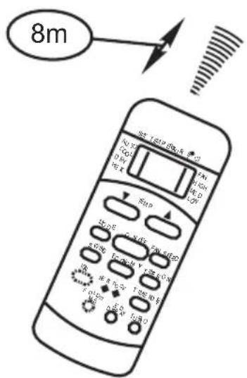
22
23

24


26


flowchart
graph LR
    A["On"] --> B["Set"]
    B --> C["Stop"]
    C --> D["Start"]
    style A fill:#f9f,stroke:#333
    style D fill:#bbf,stroke:#333
    note right of B "2 hours later after setting"
    note right of D "10 hours later after setting"


28

natural_image
Line drawing of a multi-tiered industrial air conditioner unit with ventilation grilles and mounting feet (no text or symbols)
natural_image
Line drawing of a hose connecting a wall-mounted panel, no text or symbols present29

natural_image
Line drawing of a server unit with ventilation grilles and a close-up inset showing mechanical components (no text or symbols)30
natural_image
Line drawing of a hand opening a portable air conditioner unit with cooling fins and ventilation slots (no text or symbols)SÄKERHETSANVISNINGAR
WARNING!
0.5, 1.0, 1.5, 2.0, 2.5, 3.0, 3.5, 4.0, 4.5, 5.0, 5.5, 6.0, 6.5, 7.0, 7.5, 8.0, 8.5, 9.0, 9.5, 10, 11, 12, 13, 14, 15, 16, 17, 18, 19, 20, 21, 22, 23 samt 24 timmar.
EXEMPEL PÅ TIMERINSTÄLLNING
TIMER ON (automatisk start)
0.5, 1.0, 1.5, 2.0, 2.5, 3.0, 3.5, 4.0, 4.5, 5.0, 5.5, 6.0, 6.5, 7.0, 7.5, 8.0, 8.5, 9.0, 9.5, 10, 11, 12, 13, 14, 15, 16, 17, 18, 19, 20, 21, 22, 23 samt 24 timer.
EKSEMPEL PÅ TIDSURINNSTILLING
TIMER ON (automatisk start)
$$ " W \text { góre" (+) i }," W \text { dóf" (-) } $$
Always follow the safety instructions when using electrical products. Failure to follow all the instructions and safety instructions can result in the risk of fatal injury, electric shock, fire and/or serious personal injury.
- The product can be used by children from eight years and upwards and by persons with physical, sensorial or mental disabilities, or persons who lack experience or knowledge, if they are supervised or receive instructions concerning the safe use of the pressure cooker and understand the risks involved with its use.
- The product is only intended for household use. Do not use the product outdoors.
- The product is not intended to be used by persons (children or adults) with any form of functional disorders, or by persons who do not have sufficient experience or knowledge on how to use it, unless they have received instructions concerning the use of the product from someone who is responsible for their safety.
- Keep children under supervision to make sure they do not play with the product.
- Carry out the installation in accordance with installation instructions. Incorrect installation can cause a fire, electric shock and/or water leakage.
- Only use the supplied accessories and parts and the specified tool for installation. The use of other parts, accessories or tools can result in fire, electric shock and/or material damage.
- Check that the mains voltage corresponds to the rated voltage on the type plate. The plug must be plugged into a correctly installed and earthed power point.
- Never modify the power cord or plug in
any way. Allow an authorised electrician to install an earthed power point if the plug does not fit in the power point. The power point must be fused for the product's maximum power consumption (specified on type plate). Do not use an extension cord.
- Place the product on a level, stable surface. Otherwise there is a risk of material damage, noise and/or vibration. Do not cover or block the ventilation openings on the product – risk of personal injury, material damage and/or malfunction.
- Connect the product to a separate power circuit. An incorrect connection to the mains supply can result in a risk of fire and/or electric shock.
- Do not use the product in damp or wet areas. The penetration of water can cause the electronic components to stop working.
- Do not use the product in explosive environments, such as in the vicinity of flammable liquids, gases or dust – risk of fire and/or explosion.
- The product has wheels to make it easy to move. Do not use the wheels on soft carpets and do not attempt to roll the product over objects, it can tip over.
- Do not use the product if the power cord or plug are damaged, if the product has been in contact with water, is not working properly, or if it is damaged in any other way.
- If the product has an electric heater it must not be placed closer than 1 m to any flammable material.
- Do not handle the product, power cord or the plug with wet hands.
-
Switch off the product immediately and pull out the plug if the product tips over when in use. Check for any visible damage to the product. Contact an authorised service centre or other qualified personnel if the product is damaged.
-
Switch off the product and pull out the plug during thunder storms – lightening can damage the product.
- Do not expose the product to moisture, condensation, or splashing water etc. Do not place or store the product where it could fall, or be pulled, into a bath or washbasin etc. Pull out the plug immediately if the product comes into contact with water.
- A damaged power cord or plug must be replaced by an authorised service centre or other qualified personnel to ensure safe use.
- Do not remove the product casing. Do not use the product if it is damaged or not working properly, or if the power cord or plug are damaged.
- Do not route the power cord under carpets etc. Do not route the power cord under furniture or other appliances. Place the power cord so that there is no risk of treading on it, or tripping over it.
- Do not use the product if the power cord, plug, fuse or residual current device are damaged. Discard the product or take it to an authorised service centre to be checked and/or repaired.
- Do not use the product with a speed controller – risk of electric shock. The product must be installed in accordance with the instructions and local regulations.
- Maintenance and any repairs should be carried out by qualified personnel.
- The installation should be carried out by qualified personnel.
- The product's openings must not be covered.
- The product must only be used for its intended purpose and in accordance with these instructions.
-
Switch off the product immediately and pull out the plug in the event of any abnormal noise, smell, smoke or other sign of a problem.
-
Do not press the control panel buttons with any objects, use your fingers.
- Do not start/stop the product by plugging in/unplugging the plug.
- Do not expose the product to strong or harmful chemicals. Do not use the product in explosive environments, e.g. in the vicinity of flammable liquids, gas or dust, or in environments that contain toxic or harmful substances.
- Transport the product upright.
- Switch off the product and pull out the plug when the product is not in use. Do not pull the power cord to pull out the plug.
WARNING!
- Fire risk – flammable material.
- Never use other objects or methods than those recommended by the manufacturer to defrost or clean the product. Store the product in a room without sources of heat, such as naked flame, LPG products, electric heaters, etc.
- Do not puncture or burn.
- Note that refrigerant can be odourless.
- The floor area in the room where the product is installed, used or stored, must be at least 8 m².
- Follow national regulations concerning gas.
- Keep the ventilation openings clean and unblocked.
- The product should be stored in such a way as to prevent mechanical damage.
- A warning that the product must be stored in a well-ventilated area of at least the same size as the room in which the product is intended to be used must be available.
- Refrigerant circuits must only be opened and worked on by an authorised refrigeration technician.
- Service must only be carried out in accordance with the recommendations on the manufacturer. Maintenance and/or repairs that require other qualified personnel must be carried out under the supervision of a person competent to handle flammable refrigerant.
SYMBOLS
 | Read the instructions. |
 | Approved in accordance with the relevant directives. |
 | Recycle discarded product as electrical waste. |
 | Fire risk – flammable material. |
TECHNICAL DATA
| Rated voltage 230 V | ~ 50 Hz |
| Output | 1100 W |
| Cooling power | 2300 W |
| Refrigerant | R290A |
| Energy class | A |
| Current | 4.1 A |
| Temperature range | 17–35°C |
| Cooling capacity | 8000 Btu/h |
| Dehumidifying capacity | 2.1 l/h |
| Noise level | 65 dB |
| Cord length | 1.5 m |
| Size | 350 x 700 x 360 mm |
| Weight | 23.5 kg |
REMOTE CONTROL
| Rated voltage 3.0 V |
| batteries R03 |
| Lowest voltage at which a signal can be given 2.0 V |
| Range 8 m |
DESCRIPTION
FRONT
- Control panel
- Receiver for remote control signal
- Horizontal adjustment lever
NOTE:
(manual adjustment)
- Vertical adjustment lever
NOTE:
(manual adjustment)
- Panel
- Wheel
FIG. 1
BACK
- Handle (on both sides)
- Air filter (inside grille)
- Top air inlet
- Drain
- Air outlet
- Bottom air inlet
- Drain outlet for collection tray
FIG. 2
INSTALLATION
BEFORE INSTALLATION
The place where the product is installed must comply with the following requirements.
- Place the air conditioner on a level, stable surface, otherwise there is a risk of material damage, noise and/or vibration.
- The air conditioner must be placed near an earthed power point and the collector tank (on the back) should be easily accessible.
- Leave a free space of a least 30 centimetres round the air conditioner for it to work properly.
FIG. 3
- Do not cover the inlet, outlet or signal receiver on the air conditioner – this can damage it.
Tools needed
- Phillips screwdriver, medium.
- Tape measure or ruler.
- Knife or scissors.
- Saw (to shorten window adapter for small window).
Accessories description
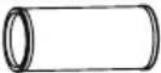
A. Product adapter
B. Outlet hose
C. Window insert adapter
D. Wall outlet adapter A (only for wall mounting)
E. Wall outlet adapter B (with cap) (only for wall mounting)
F. Screw
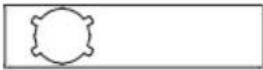
G. Window insert A
H. Window insert B
I. Screw and screw plug (only for wall mounting)
J. Foam rubber seal A (self-adhesive)
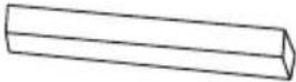
K. Foam rubber seal B (self-adhesive)
L. Foam rubber seal C (non self-adhesive)
M. Safety fastener with the 2 screws
N. Drain hose
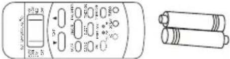
O. Remote control with battery (only for models with remote control)
FIG. 4
NOTE:
- Parts marked with * sold separately.
Window mounting kit
Preparation of outlet hose
Press the outlet hose in the window insert adapter (wall adapter for wall mounting) and in the product adapter. The elastic plastic fasteners on the adapters automatically lock the hoses.
FIG. 5
Connect the outlet hose
Insert the outlet hose in the air outlet in the direction of the arrow.
FIG. 6
Preparation of adjustable window insert
- Adjust the window insert to the size of the window.
- If the window is so long that it needs two window inserts, use the screws to join the window inserts when they are adjusted to a suitable length.
FIG. 7
INSTALLATION
NOTE:
Choose one of the three installation methods below for the outlet hose and the adjustable window insert.
Vertical sliding window
- Cut the self-adhesive foam rubber seals A and B to a suitable length and fasten them on the jamb and window frame as shown in the diagram.
FIG. 8
- Place the window insert in the window opening.
FIG. 9
- Cut the non self-adhesive foam rubber seal C to a suitable length for the width of the window. Place the seal between the glass and the jamb to prevent air and insects coming into the room.
FIG. 10
- If necessary fit the safety fastener with the 2 screws as shown in the diagram.
FIG. 11
- Place the window insert adapter in the hole in the window insert.
FIG. 12
Horizontal sliding window
- Cut the self-adhesive foam rubber seals A and B to a suitable length and fasten them on the jamb and window frame as shown in the diagram.
FIG. 13
- Place the window insert in the window opening.
FIG. 14
- Cut the non self-adhesive foam rubber seal C to a suitable length for the height
of the window. Place the seal between the glass and the jamb to prevent air and insects coming into the room.
FIG. 15
-
If necessary fit the safety fastener with the 2 screws.
-
Place the window insert adapter in the hole in the window insert.
FIG. 16
Wall mounting
- Make a hole with a diameter of 125 mm in the wall for the wall outlet adapter B.
- Fasten the wall outlet adapter B to the wall with the 4 supplied screws and plugs.
- Connect the outlet hose (with wall outlet adapter A) to wall outlet adapter B.
FIG. 17
NOTE:
- Fit the adapter cover over the hole when the air conditioner is not in use.
- For best functionality do not stretch or bend the hose. Check that there are no obstacles within 50 centimetres of the air outlet, otherwise the outlet system will not work properly. The diagrams in these instructions are only intended for illustration. The air conditioner can deviate from the diagrams in these instructions.
FIG. 18
HOW TO USE
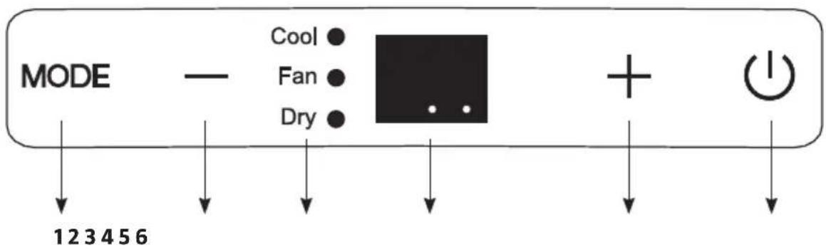
CONTROL PANEL
- MODE button
- Down (-) button
- Status lights (COOL, FAN, DRY)
- Display
- Up (+) button
- Power switch ON/OFF
FIG. 19
MODE
Used to select operating mode. Press repeatedly to switch between COOL, FAN and DRY modes. The status light indicates the set mode.
NOTE:
The fan speed is controlled automatically in these modes. The fan speed can only be adjusted manually in COOL and FAN mode.
Up (+) and Down (-)
Used to increase/reduce the set point temperature in steps of 1^ C from 17 to 30^ C, or in steps of 1^ F (or 2^ F) from 62 to 88^ F (or 86^ F).
NOTE:
The temperature can be shown in °F or °C. To change units, press the + and - buttons at the same time for 3 seconds.
ON/OFF
Starts/stops the air conditioning.
Display
Shows the set point temperature in COOL mode. The room temperature is shown in DRY and FAN mode.
| Error codes | |
| E1 | Error on room temperature sensor. |
| E2 | Error on evaporator temperature sensor. |
| E4 | Display communication error. |
| EC | Leakage of refrigerant detected (some models). |
| Warning code | |
| P1 | The tank is full. Connect the drain hose and drain off the water. Contact the retailer if the fault persists. |
NOTE:
If any of the above error codes are shown, switch off the air conditioner and check for any obstructions. Start the air conditioner. Switch off the air conditioner and pull out the plug if an error code is still shown. Contact an authorised service centre or other qualified personnel.
COOL (cooling mode)
- Continue pressing the MODE button until the COOL status light goes on.
- Set the required room temperature (set point temperature) with the + and - buttons. The temperature can be set from 17 to 30^ C or from 62 to 88^ F (or 86^ F ).
- Press the FAN SPEED button on the remote control to set the fan speed.
FAN (fan only)
- Continue pressing the MODE button until the FAN status light goes on.
- Press the FAN SPEED button on the remote control to set the fan speed. It is not possible to set the temperature.
- Do not lead the hose through the window.
DRY (dehumidification)
- Continue pressing the MODE button until the DRY status light goes on.
- In this mode it is not possible to adjust the set point temperature or fan speed. The fan motor runs at low speed. Keep doors and windows closed for best dehumidification function.
- Do not lead the hose through the window.
SLEEP/ECO
This function can only be enabled from the remote control. When the SLEEP function is enabled the set temperature increases by 1^ C/ 2^ F (or 1^ F) after 30 minutes.
After another 30 minutes the set temperature increases by another 1^ C/ 2^ F (or 1^ F). The new temperature is maintained for 7 hours, after which the original set temperature is restored. The SLEEP mode then finishes and the air conditioner runs with the original settings.
NOTE:
This function cannot be used in FAN or DRY mode.
Automatic restart
When the power supply is reset after a power failure the air conditioner restarts with the previously set function.
START DELAY 3 MINUTES
When the air conditioner has been stopped it will not start for 3 minutes. This is a safety function, and is completely normal.
REMOTE CONTROL
- Operating modes: AUTO, COOL, DRY and FAN
- 24 hour timer.
- Adjustable range for room temperature: 17 to 30^ and 62 to 88^
NOTE:
- The remote control is intended for several models and the buttons can deviate from the actual model.
- If the air conditioner does not have a specific function nothing will happen when the corresponding button on the remote control is pressed.
- The descriptions in the operating instructions apply before the diagrams for the remote control.
Positioning
The remote control has a range of 8 metres. Point the remote control at the receiver on the air conditioner. An audio prompt confirms the reception. Doors and curtains etc. can block the signal on the remote control.
FIG. 20
IMPORTANT:
- Do not expose the remote control to water or any other liquid. Do not expose the remote control to heat or direct sunlight.
- Sunlight or strong artificial light can interfere with the receiver. Protect the receiver from strong light.
- If the remote control affects other products in the vicinity, move the products or contact the retailer.
Replacing the batteries
The remote control has two batteries under a cover on the back.
- Open the battery cover.
- Remove the old batteries and insert new batteries with the correct polarity.
- Replace the battery cover.
FIG. 21
IMPORTANT:
- Do not mix old and new batteries, or different types of batteries.
- Remove the batteries if the air conditioner is not going to be used for 2 months, or more.
- Recycle used batteries in accordance with local regulations.
- All programmes are deleted when the batteries are taken out and the remote control must be reprogrammed.
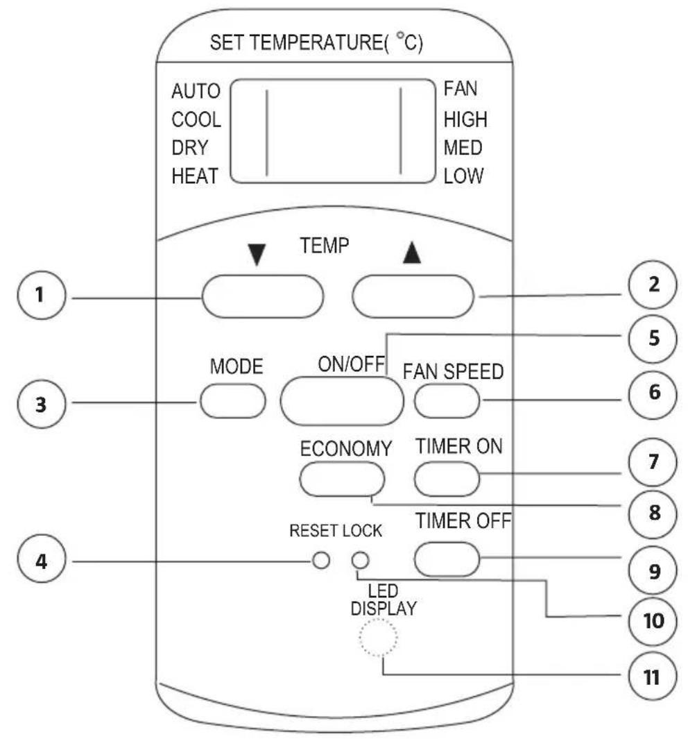
Functions
1. TEMP DOWN
Reduces the set point temperature in steps of 1^ C down to 30^ C, or in steps of 2^ F down to 88^ F.
2. TEMP UP
Increases the set point temperature in steps of 1^ C up to 17^ C, or in steps of 2^ F up to 62^ F.
3. MODE
Switches between modes in the following order:

4. RESET
Resets the remote control to default. All the settings made are lost.
5. Switch
Starts and switches off the air conditioner.
6. FAN SPEED
Switches between speed settings:

7. TIMER ON
Press to activate the setting of start delay. Each time you press the button the setting increases in steps of 0.5 hours up to 10 hours and steps of 1 hour from 10 to 24 hours. Cancel this function by setting the time to 0.0.
8. ECONOMY (SLEEP)
This function produces a comfortable temperature and saves energy when you are sleeping. The function can only be used in COOL, HEAT and AUTO mode.
NOTE:
If the air conditioner is in ECONOMY mode this is interrupted if the ON/OFF, FAN SPEED, ECONOMY or MODE button is pressed.
9. TIMER OFF
Press to activate the setting of stop delay. Each time you press the button the setting increases in steps of 0.5 hours up to 10 hours and steps of 1 hour from 10 to 24 hours. Cancel this function by setting the time to 0.0.
10. LOCK
Press this depressed button to lock the actual settings. The remote control does not respond to pressing any other buttons than LOCK. This function is used to prevent unintentional changes. Press the button again to deactivate the function. When the function is activated a lock symbol is shown on the display on the remote control.
11. LED DISPLAY
Press this button to clear the display on the air conditioner. Press again to activate the display.
FIG. 22
Readings on the display
1. Mode status
Indicates active mode (AUTO, COOL, DRY and FAN).
2. Reception status
Goes on when the air conditioner receives a signal from the remote control.
3. Temperature/timer setting
Shows set temperature (17–30°C or 62–88°F) or timer setting (0–24 hours). Not shown in FAN mode.
4. ON/OFF
Shown when the air conditioner is running.
5. FAN status mode
6. Fan speed
Shows the selected fan speed (AUTO, HIGH, MED or LOW). Not shown in AUTO or DRY mode.
7. TIMER
Shows the timer setting. The TIMER ON status light goes on if the start delay is activated. The TIMER OFF status light goes on if the stop delay is activated. Both status lights go on if both start delay and stop delay are activated.
8. Locked mode
Shown when the LOCK button is pressed. Goes off when the LOCK button is pressed again.
FIG. 23
HOW TO USE
AUTO
- Press the MODE button until AUTO mode is activated.
- Press the TEMP button to set the required temperature from 17 to 30^ C in steps of 1^ C or from 62 to 88^ F in steps of 2^ F .
- Press the ON/OFF button to start the air conditioner.
NOTE:
- In AUTO mode the air conditioner compares the actual room temperature with the set point temperature, which is set from the remote control and activates COOL, HEAT, FAN or DRY mode.
- In AUTO mode it is not possible to set the fan speed. The fan speed is controlled automatically.
- You can also set the required mode manually.
Cooling mode/fan mode
- Check that the air conditioner is connected to the mains. Press the MODE button until the required mode is activated (COOL, HEAT (only on models with both heating and cooling) or FAN).
- Press the TEMP button to set the required temperature from 17 to 30°C in steps of 1°C or from 62 to 88°F in steps of 2°F.
- Press the FAN SPEED button to set the required fan speed to AUTO, LOW or HIGH.
- Press the ON/OFF button to start the air conditioner.
NOTE:
In FAN mode the set point temperature is not shown on display on the remote control and it is not possible to change the setting. Only steps 1, 3 and 4 should be carried out.
Dehumidification
- Check that the air conditioner is connected to the mains. The status light on the air conditioner goes on. Press the MODE button until DRY mode is activated.
- Press the TEMP button to set the required temperature from 17 to 30^ C in steps of 1^ C or from 62 to 88^ F in steps of 2^ F .
- Press the ON/OFF button to start the air conditioner.
NOTE:
In DRY mode it is not possible to set the fan speed. The fan speed is controlled automatically.
TIMER
Press the TIMER ON button to activate the setting of start delay. Press the TIMER OFF button to activate the setting of stop delay.
SETTING THE START DELAY
- Press the button TIMER ON. The display on the remote control shows TIMER ON, the last set start delay, and the status in h.
- Press the TIMER ON button again to set the required start delay. Each time you press the button the setting increases in steps of 0.5 hours up to 10 hours and steps of 1 hour from 10 to 24 hours.
- When the time for TIMER ON is set a signal is sent to the air conditioner after 0.5 seconds. After another 2 seconds the h status disappears and the set point temperature is shown again on the display.
SETTING THE STOP DELAY
- Press the button TIMER OFF. The display on the remote control shows TIMER OFF, the last set stop delay and the status in h.
- Press the TIMER OFF button again to set the required stop delay. Each time you press the button the setting increases in steps of 0.5 hours up to 10 hours and steps of 1 hour from 10 to 24 hours.
- When the time for TIMER OFF is set a signal is sent to the air conditioner after 0.5 seconds. After another 2 seconds the h status disappears and the set point temperature is shown again on the display.
IMPORTANT:
Only the following times can be set:
0.5, 1.0, 1.5, 2.0, 2.5, 3.0, 3.5, 4.0, 4.5, 5.0, 5.5, 6.0, 6.5, 7.0, 7.5, 8.0, 8.5, 9.0, 9.5, 10, 11, 12, 13, 14, 15, 16, 17, 18, 19, 20, 21, 22, 23 and 24 hours.
EXAMPLE OF TIMER SETTING
TIMER ON (automatic start)
The TIMER ON function is useful, for example, to start the air conditioner automatically before you get home.
Example:
Follow the instructions below to set automatic start in 6 hours:
- Press the button TIMER ON. The display on the remote control shows the last set start delay and the status in h.
- Press the TIMER ON button repeatedly until 6:0h is shown on the display on the remote control.
- Wait about 3 seconds until the temperature display is reset. The function is now enabled.
FIG. 24
TIMER OFF (automatic switching off)
The TIMER OFF function is useful, for example, to switch off the air conditioner automatically after you have gone to bed.
Example:
Follow the instructions below to set automatic stop in 10 hours.
- Press the button TIMER OFF. The display on the remote control shows the last set stop delay and the status in h.
- Press the TIMER OFF button repeatedly until 10h is shown on the display on the remote control.
- Wait about 3 seconds until the temperature display is reset. The function is now enabled.
FIG. 25
AUTOMATIC STARTING AND STOPPING
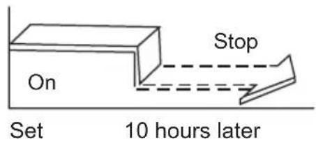
(setting of TIMER ON and TIMER OFF at the same time) TIMER OFF - TIMER ON (on — stop — start)
This function is useful, for example, to switch off the air conditioner after you have gone to bed and to start it again before you get up.
Example:
Follow the instructions below to set automatic stop in 2 hours and automatic start in 10 hours.
- Press the button TIMER OFF.
- Press the TIMER OFF button repeatedly until 2.0h is shown on the display on the remote control.
- Press the button TIMER ON.
- Press the TIMER ON button repeatedly until 10h is shown on the display on the remote control.
- Wait about 3 seconds until the temperature display is reset.
FIG. 26
This function is useful, for example, to start the air conditioner before you get up and to switch it off after you have left the house.
Example:
Follow the instructions below to set automatic start in 2 hours and automatic stop in 5 hours.
- Press the button TIMER ON.
- Press the TIMER ON button repeatedly until 2.0h is shown on the display on the remote control.
- Press the button TIMER OFF.
- Press the TIMER OFF button repeatedly until 5.0h is shown on the display on the remote control.
- Wait about 3 seconds until the temperature display is reset.
FIG. 27
IMPORTANT:
The mode that comes up first (TIMER ON or TIMER OFF) takes place first.
ECONOMY (SLEEP)
The SLEEP function produces a comfortable temperature and saves energy when you are sleeping. The function can only be used in COOL, HEAT and AUTO mode. Further information is available in the instructions.
NOTE:
If the air conditioner is in SLEEP mode this is interrupted if the ON/OFF, FAN SPEED, or MODE button is pressed.
SETTING THE AIR DIRECTION
Manual setting
• The air deflector can be set manually.
- Check that the air deflector is completely open when in heating mode.
- Check that the air deflector is open when in use.
NOTE:
- The status light for timer mode can only be set from the remote control.
- Never overload the air deflector and do not block it with any objects – risk of material damage.
Drain hose
- In dehumidification mode remove the drain plug on the back of the air conditioner and connect a drain hose (sold separately).
- Use a 3/4" hose with 5/8" coupling with internal thread. For models without a drain coupling, connect the drain hose to the hole.
- Put the end of the hose in a suitable drain.
FIG. 28
NOTE:
- Check that the hose and coupling are tight. Make sure the hose is not creased or clenched. Lead the hose to a suitable drain and make sure that the end of the hose points down.
- If continuous drainage is not being used, check that the drain plug and knob are properly inserted to prevent leakage.
MAINTENANCE
CLEANING AND CARE
WARNING!
- Pull out the plug before cleaning and/or maintenance.
- Do not use flammable chemicals for cleaning.
- Do not pour water on the air conditioner – risk of electric shock.
- Do not use the air conditioner if electrical parts have been exposed to water. A damaged power cord or plug must be replaced by an authorised service centre or other qualified personnel to ensure safe use. Cleaning the air filter.
Water level warning
- When the water level in the collector tank reaches the specified level the air conditioner gives 8 audio prompts and the display shows P1.
- The air conditioning/dehumidification stops, but the fan continues to run. Carefully move the air conditioner to a suitable drain, remove the bottom plug and allow the water to run out.
- Replace the bottom drain plug and start the air conditioner. P1 disappears from the display. Contact the retailer if the fault persists.
FIG. 29
NOTE:
Remember to firmly replace the bottom drain plug before starting the air conditioner to avoid leakage.
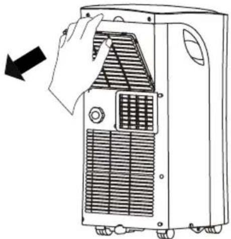
Remove the air filter
Remove the air filter as shown in the diagram.
FIG. 30
- Clean the air filter every other week for best functionality.
- Empty the tank as soon as the warning code P1 is shown. Always empty the tank before putting away, otherwise there is a risk of mould accumulating.
- If there are any pets in the house, clean the grille regularly from hairs that can block the flow of air.
NOTE:
Never use the air conditioner without a filter – dust and impurities will reduce its capacity.
Cleaning
Clean the air conditioner with a soft cloth moistened with a mild detergent. Wipe with a dry, lint-free cloth afterwards.
Storage
When the air conditioner is not in use:
- Empty the tank according to the instructions.
- Allow the air conditioner to run in FAN mode for 12 hours in a warm room to dry the inside and to reduce the risk of mildew.
- Switch off the air conditioner and pull out the plug.
- Clean the air filter according to the instructions, allow to dry and replace.
- Remove the batteries from the remote control.
NOTE:
Store in a dry and cool place. Do not expose the air conditioner to heat or direct sunlight, this can reduce the service-life.
Temperature settings
| Mode Temperature range | |
| COOL (cooling mode) | 17–35°C (62–95°F) |
| DRY (dehumidification) | 13–35°C (55–95°F) |
INSTALLATION OF OUTLET HOSE
- The outlet hose and adapter should be fitted, if necessary for the mode in use.
- The outlet hose must be fitted for COOL and AUTO mode.
- The outlet hose is not fitted for FAN and DRY mode.
TROUBLESHOOTING
The troubleshooting guide is used to determine the causes of common problems and how they can be rectified. Contact your dealer if you experience a problem that is not included in this troubleshooting guide.
| Problem Possible cause Action | ||
| The air conditioner does not start when the power switch is pressed. | Error code P1. The tank is full. Switch of the air conditioner, empty the tank and start again. | |
| In COOL mode: The room temperature is lower than the set point temperature. | Change the set point temperature. | |
| The air conditioner does not cool properly. | Air filter clogged. Switch off the air conditioner and clean the filter according to the instructions. | |
| Outlet hose blocked or not connected. | Switch off the air conditioner, release the hose, check that the hose is not blocked and connect it again. | |
| Not enough refrigerant. Have the air conditioner checked by a service technician and if necessary replenish the refrigerant. | ||
| Set point temperature too high. Set a lower set point temperature. | ||
| Doors, windows etc. have not been closed. | Close all the doors and windows. | |
| The room is too big. Check the area of the room. | ||
| Sources of heat in the room. Remove sources of heat if possible. | ||
| Noise and vibration. The surface is not horizontal. Place the air conditioner on a level, stable surface. | ||
| Gurgling sound. Caused by the flow of refrigerant in the air conditioner. | This is quite normal. | |
- SE LUFTKONDITIONERING
- SÄKERHETSANVISNINGAR
- WARNING!
- EXEMPEL PÅ TIMERINSTÄLLNING
- EKSEMPEL PÅ TIDSURINNSTILLING
- DESCRIPTION
- FRONT
- NOTE:
- (manual adjustment)
- BACK
- INSTALLATION
- BEFORE INSTALLATION
- 3
- Tools needed
- Accessories description
- 4
- Window mounting kit
- Preparation of outlet hose
- 5
- Connect the outlet hose
- 6
- Preparation of adjustable window insert
- 7
- Vertical sliding window
- 8
- 9
- 10
- 11
- 12
- Horizontal sliding window
- 13
- 14
- 15
- 16
- Wall mounting
- 17
- 18
- HOW TO USE
- CONTROL PANEL
- MODE
- Up (+) and Down (-)
- ON/OFF
- Display
- COOL (cooling mode)
- FAN (fan only)
- DRY (dehumidification)
- SLEEP/ECO
- Automatic restart
- START DELAY 3 MINUTES
- REMOTE CONTROL
- Positioning
- 20
- IMPORTANT:
- Replacing the batteries
- 21
- Functions
- TEMP DOWN
- TEMP UP
- MODE
- RESET
- Switch
- FAN SPEED
- TIMER ON
- ECONOMY (SLEEP)
- TIMER OFF
- LOCK
- LED DISPLAY
- 22
- Readings on the display
- Mode status
- Reception status
- Temperature/timer setting
- ON/OFF
- FAN status mode
- TIMER
- Locked mode
- AUTO
- Cooling mode/fan mode
- Dehumidification
- TIMER
- SETTING THE START DELAY
- SETTING THE STOP DELAY
- Only the following times can be set:
- EXAMPLE OF TIMER SETTING
- TIMER ON (automatic start)
- Example:
- 24
- TIMER OFF (automatic switching off)
- 25
- AUTOMATIC STARTING AND STOPPING
- The mode that comes up first (TIMER ON or TIMER OFF) takes place first.
- ECONOMY (SLEEP)
- SETTING THE AIR DIRECTION
- Manual setting
- Drain hose
- MAINTENANCE
- CLEANING AND CARE
- Water level warning
- Remove the air filter
- 30
- Cleaning
- Storage
- INSTALLATION OF OUTLET HOSE
- TROUBLESHOOTING
Brand : Anslut
Model : 007-018
Category : Air conditioner