416-117 - Air conditioner Anslut - Free user manual and instructions
Find the device manual for free 416-117 Anslut in PDF.


| Brand | Anslut |
| Model | 416-117 |
| Product Type | Air Conditioner (Split System Heat Pump) |
| Power Input | 0.19 - 1.7 kW |
| Heat Output | 5.5 kW |
| Cooling Output | 4.5 kW |
| SCOP | 4.6 |
| Operating Temperature Range (Heating) | -20°C to +30°C |
| Airflow Rate | 770 m³/h |
| Dehumidification Capacity | 1.4 L/h |
| Sound Pressure Level (Indoor/Outdoor) | 36 / 50 dB(A) |
| Refrigerant | R410A (1300 g) |
| Compressor Type | Inverter (Sanyo Rotary) |
| Energy Class | A++ |
| Fuse Rating | 10 A, slow blow |
| Voltage | 230 V |
| Indoor Unit Dimensions (W x H x D) | 866 x 292 x 206 mm |
| Outdoor Unit Dimensions (W x H x D) | 899 x 596 x 378 mm |
| Indoor Unit Weight | 11 kg |
| Outdoor Unit Weight | 43 kg |
| Defrost Function | On Demand |
| Drip Tray Heater (Outdoor) | Yes |
| Crankcase Heater | Yes |
| Electronic Expansion Valve | Yes |
| I-Feel Function (Remote Sensor) | Yes |
| Adjustable Horizontal/Vertical Louvers | Yes / Yes |
| Auto Restart After Power Cut | Yes |
| Maintenance Heat (+8°C) | Yes |
Frequently Asked Questions - 416-117 Anslut
User questions about 416-117 Anslut
0 question about this device. Answer the ones you know or ask your own.
Ask a new question about this device
Download the instructions for your Air conditioner in PDF format for free! Find your manual 416-117 - Anslut and take your electronic device back in hand. On this page are published all the documents necessary for the use of your device. 416-117 by Anslut.
USER MANUAL 416-117 Anslut
natural_image
Front view of a white air conditioner unit with visible grille and back panel (no text or symbols on the device itself)SE Bruksanvisning för luft/luftvärmepump
NO Bruksanvisning for
PL Instrukcja obsługi
EN User Instructions for
SE - Bruksanvisning i original
NO - Bruksanvisning i original
EN - Operating instructions in original
Date of production: 2014-06-18
© Jula AB
SVENSKA....6
SÄKERHETSANVISNINGAR....6
TEKNISKA DATA 8
BESKRIVNING 9
MONTERING....10
To consider during installation....106
Choosing installation site....106
Safety precautions for electrical appliances....107
Installation diagram....109
Check after installation and function test 115
Installation and maintenance of the air filter 117
Operation....117
Check before use 117
Remote control....117
Description of special functions 123
After use....126
GENERAL INFORMATION AND TIpS....127
MAINTENANcE 128
Cleaning and care 128
TROUBIESHOOTING....130
SÄKERHETSANVISNINGAR
INSTALLATIONSRITNING
natural_image
Simple line drawing of a container with handles and a pointed tip, no text or symbols presentUndersida


natural_image
Pure diagram of a rectangular device with internal components and connecting lines, no text or symbols presentUndersida


- Avloppsöppning
- Avloppsplugg
- Avloppskoppling
- Slang, standardslang innerdiameter 16 mm
KONTROLL EFTER INSTALLATION SAMT FUNKTIONSTEST
natural_image
Line drawing of a car air conditioner unit being lifted by two hands (no text or symbols)
12

13

natural_image
Technical line drawing of a car air conditioner unit with handle and ventilation slots (no text or symbols)HANDHAVANDE
KONTROLLERA FÖRE ANVÄNDNING
OBS!
natural_image
Diagram showing a device with internal components and directional arrows indicating motion (no text or symbols)
natural_image
Diagram showing a device interior with battery pack and directional arrows indicating movement (no text or symbols)OBS!
natural_image
Diagram of a car air conditioner unit with airflow direction indicated (no text or symbols)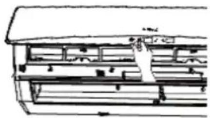
natural_image
Technical line drawing of a mechanical or electrical component with no visible text or symbols15

natural_image
Illustration of hands holding a flexible grid-patterned object with a tool, no text or symbols present16

natural_image
Technical line drawing of a mechanical device with internal components and a hand pointing to a component (no text or symbols)natural_image
Symbol of a trash bin with diagonal lines crossing it, no text or labels presentVärna om miljön!
natural_image
Pure diagram of a mechanical or electrical component with no text, numbers, or symbolsUnderside

natural_image
Pure diagram of a rectangular device with internal components and connecting lines, no text or symbols presentUnderside


INSTALLERE OG VEDLIKEHOLDE LUFTFILTERET
Installere et nytt filter
natural_image
Diagram showing two views of an air conditioner unit with arrows indicating motion (no text or symbols)12
13
natural_image
Cross-sectional diagram of a mechanical or electrical component with internal structure and directional arrows (no text or symbols)HåNDTERING
KONTROLLER FøLGENDE Før BRUK
OBS!
natural_image
Diagram showing a device interior with arrows indicating rotation and movement (no text or symbols)
natural_image
Diagram of a device with an arrow indicating assembly or operation, showing components like battery and switch (no text or symbols present)OBS!
- Batteriene må ikke erstattes med brukte batterier eller batterier av ulike typer. Det kan føre til at fjernkontrollen ikke fungerer som den skal.
- Hvis du ikke har tenkt å bruke fjernkontrollen på lengre tid, tar du ut batteriene i tilfelle de begynner å lekke.
- Bruk fjernkontrollen innenfor den spesifiserte rekkevidden.
- Bruk fjernkontrollen på minst en meters avstand fra TV-apparater og lydanlegg.
- Hvis fjernkontrollen ikke fungerer som ventet, tar du ut batteriene, venter i 30 sekunder
natural_image
Illustration of hands holding a woven fabric or mesh material, no text or symbols present
natural_image
Technical line drawing of a mechanical air conditioner unit with no visible text or symbolsFEILS∅KING
ADVARSEL!
natural_image
Pure electrical circuit lines without any symbolsSpód
natural_image
Pure diagram of a cylindrical object with internal components and connecting lines, no text or symbols presentSpód


natural_image
Diagram of two hands holding a rectangular panel with arrows indicating rotation (no text or symbols)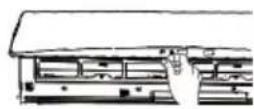
12

natural_image
Technical line drawing of a mechanical or electrical component with no visible text or symbolsKONTROLA PRZED UŻYCIEM
UWAGA!
Przycisk W LEWO / W PRAWO
natural_image
Diagram showing a device with a scroll and battery, no text or symbols present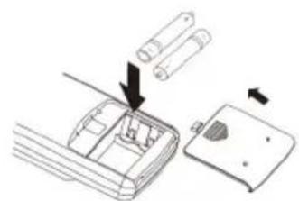
natural_image
Diagram showing a device's internal components with arrows indicating assembly or operation (no text or symbols present)UWAGA!
natural_image
Line drawing showing a car air conditioner unit being handled, with no text or symbols present.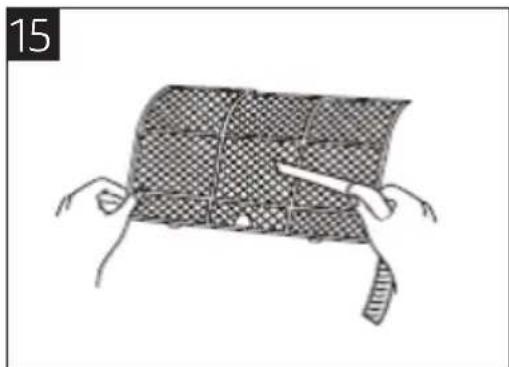
natural_image
Illustration of hands holding a woven fabric or mesh material, no text or symbols present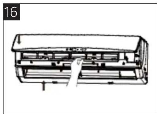
natural_image
Technical line drawing of a mechanical air conditioner unit (no text or symbols)OSTRZEŻENIE!
natural_image
Pure electrical circuit lines without any symbolsDBAJ O ŚRODOWISKO!
Read the operating instructions carefully before use!
Please retain for future reference.
WARNING!
- This appliance is not intended for use by persons (including children) with reduced physical, sensory or mental capabilities or lack of experience and knowledge, unless they have been given supervision or instruction concerning use of the appliance by a person responsible for their safety.
• Children should be supervised to ensure they are kept away from the pump. - If you smell burning, please cut off the power immediately and then contact a qualified service centre. If the air heat pump is left switched on despite a fault being discovered, the pump could be damaged, and can cause electric shocks or fire.
- Do not touch the air heat pump with wet hands. Otherwise, it may cause electric shock.
- Do not cut off or damage the power cord or control wire. A damaged power cord or control wire must be repaired by an electrician and the cord/wire must be replaced with one of a specified type.
- The mains wiring must be adapted to the working environment to avoid causing any fires. Never use a junction box or similar to connect the power cord.
- Switch off the power supply to the air heat pump if it is not going to be used for a long time. If it becomes dusty this can lead to overheating, fire and other accidents.
- Ensure the power cord does not get damaged. Do not use a type of power cord that has not been recommended. Otherwise, it may cause fire due to the power cord overheating.
- Switch off the power before you clean the air heat pump to minimise risk of electric shocks and damage.
- The power supply should always be protected by a residual current device (RCD), and must have sufficient capacity to power the air heat pump. Do not turn the air heat pump on and off too often. A Y-type connection is suitable for the air heat pump's power supply. If the power cord is damaged, it must be replaced by the manufacturer, a service centre or similar.
- If the voltage is too high, electrical parts inside the pump could be damaged, if the voltage is too low the compressor will vibrate fiercely, which can damage the cooling system or compressor, and the electrical components will stop working.
- Check the pump is correctly earthed. If the pump is not earthed it could give electric shocks.
- For safety reasons you should switch off the main power switch before you perform any maintenance or clean the air heat pump, and also when you are not planning to use the device for a long time. Accumulated dust may cause fire or electric shocks.
- Select the most appropriate temperature. The room should be about 5 degrees cooler than the outside temperature. This way you can save energy.
- Do not keep windows and doors open for a long time during operation, otherwise the air heat pump will not work particularly well.
-
Do not block the air inlet or outlet. This will mean the pump will not function as it should and could cause malfunctions.
-
Keep all combustible materials at least 1 metre away from the pump. They could lead to fire or explosions.
• Install the outdoor unit properly, as the pump could fall and injure someone. - Never climb on the outdoor unit or place any heavy objects on top of it. This could cause material damage or personal injury.
- Do not attempt to repair a broken air heat pump by yourself. Incorrectly executed repairs could lead to electric shock or fire.
- Ensure the power cords and control cords do not get damaged. Contact qualified service personnel if they are damaged.
- Do not insert your hands or objects into the air inlet or outlet. This could cause an accident.
- Do not expose animals or plants directly to the air flow. This could have a harmful effect on them.
- Do not expose yourself to cold air flowing from the pump for longer periods. It is not good for your health.
- Do not use the air heat pump for any other purpose, such as refrigerating food or drying clothes.
- Do not splash water on the air heat pump. This may cause electric shock or malfunction.
- Do not place a gas oven or similar near the air heat pump. This could cause CO toxicosis due to incomplete combustion.
TEcHNICAL DATA
| Power | 0.19-1.7 kW |
| Heat output 5.5 kW (3.65 W) | |
| Cooling output 4.5 kW (3.5 W) | |
| SCOP | 4.6 |
| Heat power temperature range -20°C - +30°C | |
| Airflow rate 770 m3/h | |
| Dehumidification capacity 1.4 L/h | |
| Sound pressure level indoors/outdoors 36/50 dB(A) | |
| Refrigerant R410A (1,300 g) | |
| Refrigerant connector Flange 1/4+3/8 | |
| Compressor control Inverter | |
| Compressor Sanyo Rotary | |
| Energy class A++ | |
| Fuse | 10 A, slow blow |
| Voltage | 230 V |
| Measurements indoor/outdoor component | W 866 x H 292 x D 206/W 899 x H 596 x D 378 mm |
| Weight indoor/outdoor component | 11/43 kg |
| Defrost on demand option | Yes |
| Drip tray heater for outdoor component | Yes |
| Crankcase heater for compressor | Yes |
| Electronic expansion valve | Yes |
| I-feel function (Temperature sensor on remote control) | Yes |
| Adjustable horizontal/vertical damper | Yes/Yes |
Automatic start-up after power cut Yes
Maintenance heat +8°C Yes
Suitable for up 130 m^2 (the figure is an estimation which can be affected by the insulation and climate of the building).
DEScRIpTION
Indoor unit
- Horizontal Louvre
- Filter
- Front panel
- Power cord
- Wall pipe
- Binding tape
- Remote control
- Connection pipe
- Drain hose
- Drain connector

Air heat pump for heating and air conditioning
ASSEMBLy
TO CONSIDER DURING INSTALLATION
WARNING!
- Installation of the air heat pump should only be carried out by a qualified professional and in accordance with local regulations and these operating instructions.
- Before the installation you should contact a local qualified installation company. If the air heat pump is not installed by a qualified fitter, it may not be possible to repair any faults.
- You should also contact your local installation company if you need to move the air heat pump.
- Caution: Before any kind of work on power circuits, all power supply must be fully disconnected.
- If the power cord is damaged, it should be replaced by the manufacturer or by a qualified service centre/electrician.
- The air heat pump must be positioned in such a way that makes the plug easily accessible.
- The refrigerant circuit can get very hot, so the power cord should be kept at a suitable distance from the copper pipe.
- This appliance is not intended for use by persons (including children) with reduced physical sensory or mental capabilities, or lack of experience and knowledge, unless they have been given supervision or instruction concerning use of the appliance by a person responsible for their safety.
- Children should be supervised to ensure that they do not play with the appliance.
cHOOSING INSTALLATION SITE
A suitable installation site is extremely important to ensure the air heat pump can function correctly and efficiently. Avoid the following sites where:
– strong heat sources, vapours, flammable gas or volatile liquids are emitted.
– high-frequency electro-magnetic waves are generated by radio equipment, welders or medical equipment
– salt-laden air prevails (for example in coastal areas)
– the air is contaminated with industrial vapours or oils
– the air contains sulphurous gases (such as in areas with hot springs)
– there is often poor air quality or a corrosive atmosphere (causes rust)
choosing indoor unit installation site
- The air inlet and outlet should be kept away from any obstacles or objects. Ensure the air can be blown into the whole room.
- Choose a site where the condensing water can be easily drained out, and where it can be easily connected to the outdoor unit.
- Choose a site that is out of reach of children.
- Choose a wall for the installation that is strong enough to hold the full weight and vibrations of the
unit.
- Be sure to leave enough space to allow access for routine maintenance. The unit should only be installed 25 cm above ground level or higher.
- Choose a site that is at least one metre away from any TV sets or other electrical/electronic equipment.
- Choose a site where you can easily remove the filter.
- Make sure that the indoor unit is installed in accordance with installation dimension instructions.
- Do not install the indoor unit in a damp space, for ex. laundry room or by a swimming pool.
choosing outdoor unit installation site
- Choose a site where noise and outflow air from the outdoor unit will not disturb your neighbours.
- Choose a site where there is good ventilation.
- There should be no objects blocking the air inlet and outlet.
- The installation site should be able to hold the full weight and vibrations of the unit.
- Choose a dry place which is not exposed to direct sunlight or strong winds.
- Make sure that the outdoor unit is installed in accordance with the installation instructions, and is conveniently placed for maintenance and repair.
- The height difference between the indoor and outdoor units should be at most 10 metres.
- The connecting hose between the units must not exceed the following lengths: for 09K, at most 15 metres; for 12K at most 20 metres.
- Choose a site that is out of reach of children.
- Choose a site that does not block the passage of pedestrians or negatively affects the look of its surroundings.
SAFETy pRECAUTIONS FOR ELEcTRlCAL AppLIANcES
NB:
- Make sure the three cables are properly connected in the connection box. The connection diagram shows how the circuit should work.
- Incorrect electrical connections can cause electric shocks or fire.
- A dedicated power supply circuit should be used in accordance with local electrical safety regulations.
- Do not pull on the power cord.
- The air heat pump should be earthed and connected to an RCD. This should be carried out by a qualified electrician.
- The RCD must have the appropriate functions for protecting against short circuits and overloading.
- The minimum distance between the air heat pump and a combustible surface is 1.5 metres.
-
The air heat pump must be installed in accordance with local electrical safety regulations.
-
An isolator switch where all poles are separated by at least 3 mm must be included when laying fixed wiring. For models with a power plug, make sure both the socket and the plug are within easy reach, even after installation.
- An air fuse with suitable capacity should be included, see the table below. The RCD should have both a magnet and heat function to protect against both short circuiting and overloading.
- The fuse is not intended to be used solely to protect the circuit.
| Air heat pump (BTU) RCD | |
| 09, 12K 16 A |
Earthing
- The air heat pump is a type 1 electrical appliance. Ensure the unit is properly earthed.
- The yellow-green cable is intended for earthing, and cannot be used for any other purpose. Improper earthing may cause electric shock.
- The earth resistance should fulfil national requirements.
- The electrical installation at the installation site should be correctly earthed. Never connect the earth wire to any of the following: water pipes, gas pipes, drainage pipes, any other places that a qualified electrician would consider inappropriate.
- The fuses should be of the type and capacity indicated on the cover of the fuses or the current PCB.
INSTALLATION DIAGRAM
Minimum permissible distances to adjacent objects or building components for correct installation.

INSTALLATION OF INDOOR UNIT
Installation of mounting bracket
The mounting bracket should be installed horizontally. As the indoor unit's water tray is a two-way type, the indoor unit should be slightly slanted in the direction of the outlet to ensure the condensing water can run off properly.
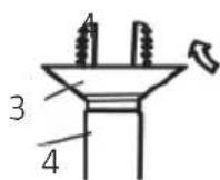
- Fix the mounting bracket to the wall using screws (figure 1).
- Ensure the mounting bracket can hold 60 kg. The weight should be evenly distributed across every screw.

Drilling a hole for the pipe
- Angle the hole for the pipe ( 55/70) on the wall slightly downward toward the outdoor unit (figure 2).
- Insert the sleeve into the hole to prevent the pipe and wiring from being damaged when passing through the hole.

Installing the drainage hose
NB: The insulation tube must be properly connected to the drainage pipe's casing. The drainage hose should be slightly angled downward, without bends or any other distortions. Do not immerse the end of the drainage hose in water.
- Connect the drainage hose to the drainage pipe of the indoor unit (figure 3).
- Attach the hose with the rubber straps.
- Insert the drainage hose into the insulation tube.
- Wrap the insulation tube with wide rubber tape to prevent the tube from moving. Angle the drainage hose downward slightly for smooth drainage of condensing water.
3
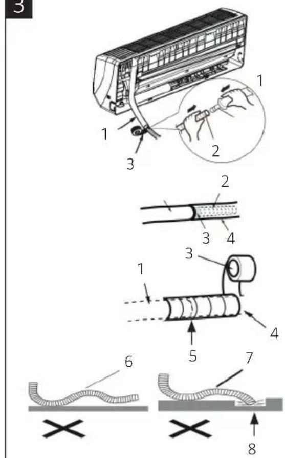
- Drainage pipe for indoor unit
- Drain hose
- Rubber tape
- Insulation tube
- Joint
- Bend
- Twisted
- Flooded
Connect the indoor and outdoor electrical wires.
NB:
- All wiring between the indoor and outdoor units must be carried out by a qualified electrician.
- Electrical wires must be connected correctly. Improper connection may cause malfunction.
- Tighten the screws in the terminal board tightly.
• After tightening the screws, pull the wire slightly to check it is correctly fixed in place. - Ensure the electrical connections are correctly earthed to avoid risk of electric shocks.
-
Ensure all wires are connected correctly and securely, and that covers and front panels are closed properly. Poor installation may cause fire or electric shock.
-
Open the front panel.
- Remove the connection box cover and cable clamp. Insert the power cord through the hole on the back of the indoor unit.
-
Connect and fix the power cord to the terminal board (as shown in figure 4).
-
Fix the power cord in place with the cable clamp and replace the cover over the connection box.
-
Reinstall the front panel.

Installation of indoor unit
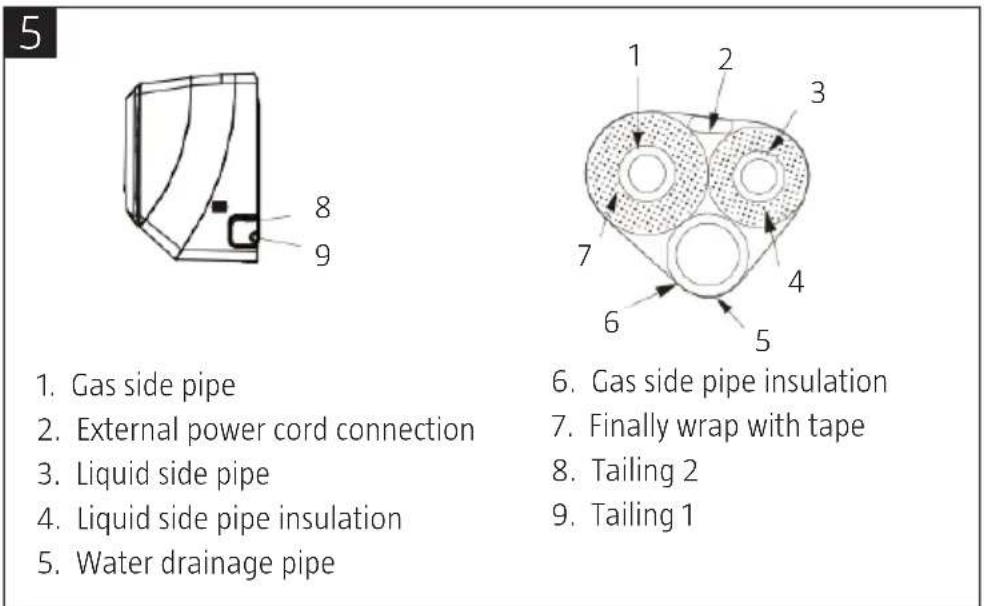
The pipes can be run through from the right-hand side, right-hand rear end, left-hand side or left-hand rear end. When routing the pipes and wiring from the left or right-hand side of the indoor unit, cut off the tailings from the housing when necessary.
-
Cut tailing 1 if you are only routing cables here. Cut both tailings 1 and 2 when you plan to route both cables and pipes here (figure 5).
-
Run the pipes from the chassis and wind tape around the pipes, power cord, drainage hose and then pass them through the opening (figure 6).
-
Hang the indoor unit on the upper hooks of the mounting bracket (figure 6) and make sure it is properly secured. The unit should only be installed 25 cm above ground level or higher.

Installing the connection pipe
- Align the pipe flange so that it is centred with the valve (figure 7).
- Screw in the nut by hand and then tighten the nut with a spanner and torque wrench, referring to the following table:
| Nut diameter Tightening torque (Nm) | |
| 6 15-20 | |
| 9.52 30-40 | |
| 12 45-55 | |
| 16 60-65 | |
| 19 70-75 | |
NB: The pipe should first be connected to the indoor unit, and then to the outdoor unit. Bend the pipe carefully. Do not damage the connection pipe. Ensure that the nut is tightened properly, otherwise there may be leakage.

Laying the power cord
- Remove the handle from the right-hand side of the outdoor unit.
- Remove the cable clamp. Connect the power cord to the terminal board (figure 8). The wiring should correspond to that done for the indoor unit.
- Fix the power cord in place using the cable clamp.
- Ensure the cable is secured properly.
- Reinstall the handle.

Air purging and leakage test
-
Connect the pressure hose from the manifold valve to the pressure end of the low pressure valve (both high/low pressure valves must be closed).
-
Connect the pressure hose connector to the vacuum pump.
- Open the low pressure valve fully.
- Open the vacuum pump for compression. At the beginning of the process, slightly loosen the nut for the low pressure valve to check if air is being pumped in. (If the noise from the vacuum pump has changed, the manometer will show a reading of 0). Now tighten the nut.
- Keep adding compressed air to the system for 15 minutes or more until the manometer reads -1.0x10⁵ Pa (-76 cmHg).
- Fully open high/low pressure valves.
- Remove pressure hose from low pressure valve.
- Tighten low pressure valve (figure 9).

- High-pressure valve (Hi) closed
- Vacuum pump
- Gas valve
- Liquid valve
- Low-pressure valve (Lo) open
- -76 cm Hg
Outdoor condensation drainage (only for heat pump units)
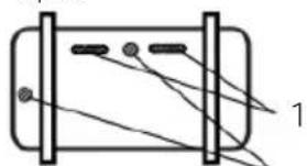
- When heating mode (HEAT) is in use, the condensation and defrosting water should be able to run out through the drainage hose. Connect the hose connector to the drainage hose in the ∅25 or ∅42 mm drainage hole on the base plate of the outdoor unit. Then connect the drainage hose to the hose connector. The drainage hole that is not being used should be plugged.
- Local conditions will determine what type of drainage opening should be used.
- The 09 and 12K TB drainage holes consist of two 42 mm and two oval holes. For these models there is one 42 mm plug and two oval plugs (figure 10).
CHECK AFTER INSTALLATION AND FUNCTION TEST
Check after installation
| Items to be checked Possible malfunction | |
| Has the pump been secured properly? The pump may fall, vibrate or emit noise. | |
| Has a refrigerant leakage test been carried out? The cooling/heating process could become inefficient. |
10

natural_image
Pure diagram of a cylindrical device with internal components and connecting wires, no text or symbols presentBottom frame

- Drainage opening
- Drain plug
- Drain connector
- Hose, standard hose inner diameter 16 mm

natural_image
Pure diagram of a cylindrical object with internal lines and two dots, no text or symbols presentBottom frame


| Is there sufficient insulation? Condensation can occur. | |
| Is the run-off/drainage satisfactory? This could lead to water leakage. | |
| Is the voltage in accordance with the rated voltage marked on the nameplate? | This may cause electrical malfunction or damage the unit. |
| Is the electric wiring or piping connection installed correctly and securely? | This may cause electrical malfunction or damage the unit. |
| Has the unit been correctly earthed? This may cause electrical problems. | |
| Does the power cord have the correct specifications? | This may cause electrical malfunction or damage the unit. |
| Is the inlet or outlet blocked? The cooling/heating process could become inefficient. | |
| Have the pipe lengths and refrigerant specifications been properly observed? | Incorrect refrigerant capacity. |
Function test
- Before function test is carried out
- Do not switch on power before installation is finished completely.
- Electric wiring must be connected correctly and securely.
- Cut-off valves on the connection pipes should be opened.
- The air heat pump should be cleaned.
-
Carry out the function test
-
Switch on the power and press the "ON/OFF" button on the remote control to start the air heat pump.
- Press the MODE button to select in turn the cooling (COOL), heating (HEAT) (there are no units which only have cooling) and fan (FAN) modes and check whether they are functioning correctly.
INSTALLATION AND MAINTENANCE OF THE AIR FILTER
Installing a new filter
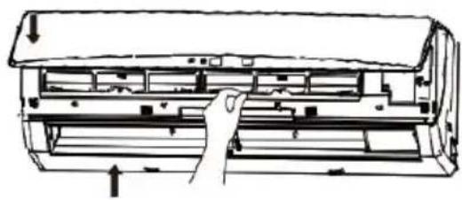
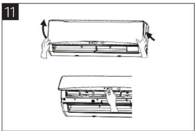
- Lift up the front panel from both sides, as shown by the arrows in the figure, and then remove the air filter (figure 11).
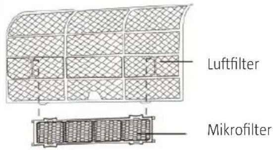
- Attach the microfilter to the holder on the air filter, as shown in the figure below (figure 12).
- Reinstall the air filter as shown in figure C, and then close the front panel again (figure 13).
natural_image
Line drawing of a car air conditioner unit with two views showing internal components and airflow direction (no text or symbols)

natural_image
Technical line drawing of an air conditioner unit with hand operating the interior panel (no text or symbols)OpERATION
cHEcK BEFORE USE
NB:
- Ensure nothing is covering the air outlet or inlet.
- Check that the air heat pump is correctly earthed.
- Check that the batteries are in the remote control and are working.
- Check that the outdoor unit is installed in a stable way. If it is not, contact a qualified service centre.
REMOTE CONTROL
NB:
- There should not be any objects between the air heat pump and the remote control.
- Be careful with the remote control, it is fragile.
- Don't let the remote control get wet or place the remote control in direct sunlight or close to very hot objects.
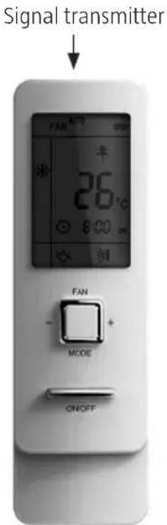

natural_image
Two open mobile phone modules showing front and back views with digital dials and control buttons (no readable text or symbols)
AUTO

Cooling (COOL)

Dehumidification (DRY)

Fan (FAN)

Heating (HEAT)

Power switch

Set temperature
General use
NB: When you start the pump, the control louvre on the main unit will close automatically.
- When you press the ON/OFF button, the unit starts.
- Press the MODE button to choose your desired operating mode.
- Press the + or - buttons to set your desired temperature (not needed if you have chosen automatic mode).
- Using the FAN button you set the fan speed to AUTO FAN, LOW, MEDIUM-LOW, MEDIUM, MEDIUM-HIGH or HIGH.
- Press ➕ or ➕ to change the direction of the ventilation louvres.
Other functions
- Press the SLEEP button to activate night mode.
- Press TIMER ON and TIMER OFF to start or stop the timer function.
- Press the LIGHT button if you want to start/stop the lighting on the unit (this function is not included on all units).
- Press the TURBO button to start/stop the turbo function.
ON/OFF button
Press the button once to start the air heat pump, press once more to turn it off. The power-saving mode cannot not be used when the air heat pump is turned off.
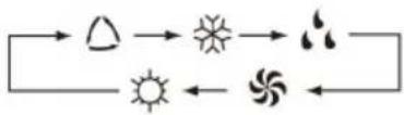
MODE button
- You can switch between automatic (AUTO), cooling (COOL), fan (FAN) and heating (HEAT) modes by pressing this button repeatedly.
- Auto (AUTO) is the default setting when the pump is started. If automatic (AUTO) mode is activated, the temperature is not displayed.
- The heating (HEAT) mode has a basic setting of 28^ C . For other modes, the basic temperature is 25^ C .
flowchart
graph LR
    A["Sun"] --> B["Moon"]
    B --> C["Moon"]
    C --> D["Moon"]
    D --> E["Sun"]
    E --> F["Moon"]
    F --> G["Moon"]
FAN button
- You can switch between automatic (AUTO), low (LOW), medium-low (MEDIUM LOW), medium-high (MEDIUM-HIGH) and high (HIGH) speeds by pressing this button repeatedly.
- The automatic fan speed (AUTO) is the default setting when the pump is started.
- In dehumidification (DRY) mode, only a low fan speed can be selected.
TEMp button
NB: You can see the outdoor temperature displayed between 0-60°C. If it is below 0 degrees outside, 0°C will be displayed.
- You can switch between different temperatures by repeatedly pressing this button. Set temperature, indoor temperature and outdoor temperature.
- When you start the indoor unit, it will show the set temperature to begin with ↗.
- The symbol ⏻means the indoor temperature is displayed, and ⏻the outdoor temperature. After 5 seconds the display will go back to the set temperature again.

flowchart
graph TD
    A["ATUO"] --> B["Low"]
    A --> C["Medium"]
    A --> D["High"]
    B --> E["Medium-low"]
    C --> F["Medium-high"]
    D --> G["Medium-low"]
    D --> H["Medium-high"]
cLOcK button
- Press this button to set the clock. The ⏻ symbol will flash. Press the + or - button within five seconds to change the time. If you hold down the button for two seconds or more, the time will change more quickly, by ten minutes per half a second if you keep the button pressed down. Once you have set the clock correctly, press the clock button again. The symbol will stop blinking to indicate that the time has been set successfully.
- When the air heat pump is started, 12:00 will show as standard, along with the ⏻ symbol. If the ⏻ symbol is displayed then that is the actual time being displayed, whereas if the symbol is not displayed then it is the timer setting that is being displayed instead.
LIGHT button
- Press the light button to start or stop the lighting.
- When the unit is started, the lighting is switched on as standard.
TURBO button
- Use this button to turn on or turn off the turbo function in cooling (COOL) or heating (HEAT) modes. The turbo symbol is displayed if the function is turned on.
- The function is automatically turned off if you change the mode or fan speed.
X-FAN button
- If you press the X-FAN button when either the cold air (COOL) or dehumidification (DRY) mode is activated, the symbol 🌿 will be displayed and the indoor fan will continue to run for 10 (2) minutes to dry out the indoor unit even after you have switched the pump off.
- When the air heat pump is started, the X-FAN function is switched off as standard. X-FAN cannot be used in automatic (AUTO), fan (FAN) and heating (HEAT) modes.
+ button
- Can be used to increase the pre-set temperature.
- Press this button to change the set temperature. If you hold the button down for longer than two seconds, the value will change more quickly.
- You cannot change the temperature in automatic mode (AUTO). You can set the air heat pump to between 16 and 30 degrees.
- button
- Can be used to reduce the pre-set temperature.
- Press this button to change the set temperature. If you hold the button down for longer than two seconds, the value will change more quickly.
- You cannot change the temperature in automatic (AUTO) mode.
QUIET button
- Press this button to switch between automatic silent mode (the 📞 symbol and "Auto" will be displayed), silent mode (the 📞 symbol will be displayed) and no silent mode ( 🔍 not displayed).
- When the air heat pump is started, the silent mode is switched off as standard (no 🔒 symbol).
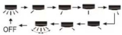
Up/DOWN button

- Press this button to change the angle of the ventilation louvres in the following order:

- This remote controller is universal. This air heat pump cannot be set to the following modes despite being displayed on the remote control:

This symbol displays the ventilation louvre's various possible positions.
LEFT/RIGHT button
Press this button to change the angle of the ventilation louvres in the following order:
flowchart
graph TD
    A["Start"] --> B["Step 1"]
    B --> C["Step 2"]
    C --> D["Step 3"]
    D --> E["Step 4"]
    E --> F["Step 5"]
    F --> G["OFF"]
    G --> H["Step 6"]
    H --> I["Step 7"]
    I --> J["Step 8"]
TIMER ON button
- Start the timer: When you press TIMER ON, the symbol disappears, the "ON" symbol flashes and the number area on the display will now be used for setting the timer. The "ON" symbol will flash for five seconds, and during this time you must press the + or - buttons to begin setting the time.
• Each time you press + or - the value will increase or reduce by one minute. If you hold the + or - buttons down, the selection will go faster after two seconds. You can then change the setting by ten minutes at a time. - Then press the TIMER ON button while the ON symbol is still flashing to set the time. The time is turned off by pressing the same button again. Remember to set the clock to the right time before you set the timer.
TIMER OFF button
Press once to set the air heat pump to off mode. The TIMER OFF symbol will then flash. The setting is done in the same way as for TIMER ON.
I FEEL button
- I FEEL is a function which allows you to control the temperature more accurately where the remote control is located.
- Press the I FEEL button once to start the function ("I FEEL" will be displayed on the screen). Now the remote control will send information every ten minutes to the air heat pump, indicating how high the temperature is where it is located. Press this button again to turn the function off.
FLOW MODIFICATION butto
These functions are not available in Anslut 416117. In this mode the fan is only activated for low speed.
SLEEp button
By pressing the SLEEP button, you can circulate between activating night reduction mode, Sleep 1 (1), Sleep 2 (2) Sleep 3, (3) as well as turning off the night reduction mode. When the air heat pump is started, this function is switched off as standard.
- SLEEP 1 in cooling mode (COOL) and dehumidification mode (DRY): night mode is activated after one hour, whereupon the set temperature increases by 1^ , after two hours the set temperature increases by 2^ . After this the pump operates on the set temperature.
In cooling mode (COOL)
- If the set temperature is set between 16–23°C and night mode is activated, the temperature will increase by 1°C per hour. When the temperature has increased by 3°C, the air heat pump will operate under this setting for 7 hours, after which the temperature will be reduced by 1°C, and after this the pump will operate at that temperature.
- If the set temperature is set between 24–27°C and night mode is activated, the temperature will increase by 1°C per hour. When the temperature has been increased by 2°C, the air heat pump will operate under this setting for 7 hours, after which the temperature will be reduced by 1°C, and after this the pump will operate at that temperature.
- If the set temperature is set between 28–29°C and night mode is activated, the temperature will be increased by 1°C per hour. When the temperature has been increased by 1°C, the air heat pump will operate under this setting for 7 hours, after which the temperature will be reduced by 1°C, and after this the pump will operate at that temperature.
- If the set temperature is set at 30^ and night mode is activated, the temperature will be reduced by 1^ after 7 hours, and after this the pump will operate at this temperature.
- SLEEP 1 in heating mode (HEAT): night mode is activated after one hour, when the temperature is reduced by 1^ , and after two hours the set temperature will be reduced by 2^ . After this the pump operates on the set temperature.
In heating mode (HEAT)
- If the pre-set temperature is set at 16^ , the air heat pump will operate constantly under this setting even when night mode is activated.
- If the set temperature is set between 17 - 20^ and night mode is activated, the temperature will be reduced by 1^ per hour. When the temperature has been reduced by 1^ , the air heat pump will operate continuously under this setting.
- If the set temperature is set between 21–27°C and night mode is activated, the temperature will be reduced by 1°C per hour. When the temperature has been reduced by 2°C, the air heat pump will operate continuously under this setting.
- If the set temperature is set between 28–30°C and night mode is activated, the temperature will be reduced by 1°C per hour. When the temperature has been reduced by 3°C, the air heat pump will operate continuously under this setting.
- SLEEP 2 means that the air conditioning is running in accordance with a pre-set temperature curve.
- SLEEP 3 is where you set the temperature curve yourself, and you can also check which settings you have done for this night mode:
- First activate night mode Sleep 3. Then hold down the "Turbo" button. Now "1 hour" will start to flash on the remote control's display, and the temperature from the most recent setting will be displayed. The temperature value will also flash. (When you use the function for the first time, factory settings will be displayed).
- Use the + and - buttons to change the temperature, and confirm the setting by pressing the Turbo button.
- You can now change the flashing timer setting instead (for ex. to 2, 3 or 8 hours).
- Repeat steps 2-3 until you have completed the settings for an entire 8-hour period. When you have finished, the remote control will return to the normal timer display, and the temperature display will once again be the originally set temperature.
You can start the night mode 3 according to step 1 above, but instead of entering any new settings, press the Turbo button when you have checked the current settings.
NB: If you do not press any button on the remote control within ten seconds of starting any of the aforementioned setting procedures, the remote control will automatically return to normal mode. You can also terminate the procedure whenever you want by pressing any of the following buttons: ON/OFF, MODE, TIMER or SLEEP.
DESCRIPTION OF SPECIAL FUNCTIONS
About the X-FAN function
This function is used to dry out the evaporator in the indoor unit after it has stopped so that mould does not get the chance to grow.
- When the X-FAN function is on: When you have switched the air heat pump off by pressing the ON/OFF button, the indoor fan will continue to run on low speed for approximately 10 (2) minutes. During this period you can press the X-FAN button if you want to stop the fan immediately.
- When the X-FAN function is off: When you have turned the air heat pump off by pressing the ON/OFF button, the entire system will turn off immediately.
About AUTO RUN mode
When you select AUTO RUN mode, the set temperature will not be displayed on the remote control's display. The air heat pump will then operate in fully automatic mode and suitable settings are selected to give you a pleasant indoor climate.
About the TURBO function
You can use this function to run the air heat pump's fan at extra-high speed. This means the indoor temperature will reach the set level more quickly, for both hot and cold settings.
About the lock function
Press the + and – buttons simultaneously to lock or unlock the keyboard. When the remote control is locked, the symbol will appear on the display. If you press any button while in this mode, the symbol will flash three times. If the keyboard is unlocked, the symbol will disappear.
About the UP/DOWN function
- If you hold the UP/DOWN button down for longer than two seconds, the settings for the ventilation louvre will switch between angled up and angled down mode. When you release the button, the air diffuser will stop in its current position.
- If you have pressed the ➕ button to activate the UP/DOWN setting and press ➕ again within two seconds, the function will be switched off immediately. If you press the same button again within two seconds, the UP/DOWN position will also depend on where you were previously in the sequence.
About the LEFT/RIGHT function
- If you hold the LEFT/RIGHT button down for longer than two seconds, the settings for the ventilation louvre will switch between left-angled and right-angled mode. When you release the button, the louvre will stop in this position.
- If you have pressed the 📄 button to activate the UP/DOWN setting and then press 📄 again within two seconds, the function will be switched off immediately. If you press the same button again within two seconds, the LEFT/RIGHT position will also depend on where you were previously in the sequence.
Switch between Celsius and Fahrenheit
Switch the air heat pump off. Then press simultaneously on the MODE and - (minus) buttons to switch between Celsius and Fahrenheit.
About the energy-saving function in cooling mode (COOL)
Activate cooling mode (COOL). Then press simultaneously on the TEMP and CLOCK buttons to activate the energy-saving function. Now "SE" will appear on the remote control's display. Turn the function off in the same way.
About energy-saving mode in HEAT mode
Activate heating mode (HEAT). Then press the TEMP and CLOCK buttons simultaneously to activate maintenance heat at 8°C. Now the Ⓞ symbol and the temperature of 8°C will appear on the remote control's display. Turn the function off in the same way.
QUIET function
When activating the QUIET function for silent operation
- In cooling mode (COOL): The indoor fan will operate at level 4. After 10 minutes, or when the indoor temperature is at ≤ 28^ , the fan will then operate at level 2 or in silent mode, based on how great the difference is between the desired temperature and the actual indoor temperature.
- In heating (HEAT) mode: The indoor fan will run on level 3 or in silent mode, based on how large the difference is between the desired temperature and current indoor temperature.
- In dehumidification (DRY) mode: The indoor fan will run in silent mode.
- In automatic (AUTO) mode: The indoor fan will run in silent mode based on the current cooling, heating or fan mode.
Night mode function (SLEEp)
The SLEEP function can only be used with fan mode (FAN) and automatic mode (AUTO). Only SLEEP 1 can be selected for dehumidification mode (DRY). If you start any type of night function (SLEEP), silent mode will also be selected, but you can where necessary select another silent mode or turn it off entirely.
Batteries
- Press the battery cover and slide it in the direction of the arrows to open.
- Take out the old batteries.
- Insert two new AAA 1.5 V batteries. Ensure they are facing the right way.
- Put the battery cover back in place.

natural_image
Diagram showing two steps of battery charging process: one with directional arrows indicating rotation, the other with no text or symbols.NB:
- Do not replace the batteries with used batteries or a different type of battery. This could mean the remote control does not function as it should.
- If you do not intend to use the remote control for a long period, you should take out the batteries because they may begin to leak.
- Use the remote control within its specified range.
• Use the remote control at a distance of at least one metre away from any TV sets or sound systems. - If the remote control does not function as expected, take out the batteries, wait 30 seconds then put the batteries back in again. If this does not help, replace the batteries.
• Always direct the remote control at the air heat pump for best results. - When the remote control sends out a signal, the symbol ⚙shes for approximately one second. A noise will sound if the air heat pump has received the signal.
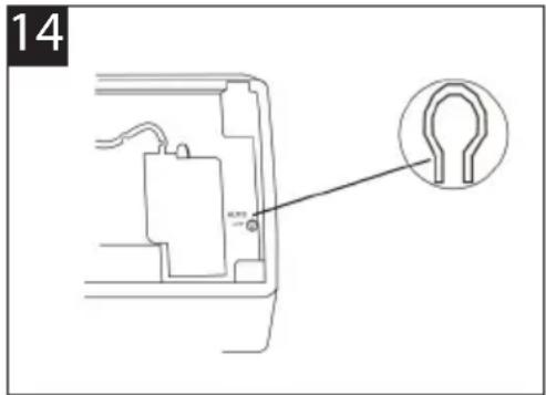
Emergency operation
When the remote control is lost or damaged, you can use the manual switch on the air heat pump (figure 14). You will however only be able to operate the pump in automatic mode (AUTO), and it is not possible to change the temperature setting or fan level.
The manual switch can be operated as below:
- Turn the air heat pump on: Press the AUTO/STOP button to start the pump in automatic mode. At this point the right mode will automatically be selected (COOL, HEAT or FAN) to ensure you have a pleasant indoor climate.
- Turn off the air heat pump: press the AUTO/STOP button to turn off the pump.
The operation mode is explained in the table below.
| Mode Model Temperature setting Airflow rate | ||
| AUTO Cooling 25°C COOL/FAN AUTO | ||
| AUTO Heating 25°C COOL/FAN AUTO | ||
| AUTO Heating 20°C HEAT AUTO | ||
NB: This button should only be used when the remote control cannot be used.
AFTER USE
Turn the air heat pump off using the main power switch.
- Clean the filter and exteriors of both the indoor and outdoor units.
- Wipe off dust from the outdoor unit and remove any rubbish.
- Any rust patches on the outdoor unit should be repaired as soon as possible to stop the rust spreading.
- It is recommended to use the specially-adapted cover to protect the outdoor unit from rain and dust.
GENERAL INFORMATION AND TIPS
| Operating Temperature R※e | ||
| Indoor dry/wet weather. Outdoor dry/wet weather. | ||
| Maximum cooling 32/23°C 48/— °C | ||
| Maximum heating 27/-- °C 24/18°C | ||
Operating area, outside temperature
– During cooling operation the lowest outdoor temperature is -15 degrees.
– During heating operation the lowest outdoor temperature is -20 degrees.
Cooling
- Principle
– Air conditioning units absorb heat in the room and transmit it to the outdoor unit, thereby reducing the room temperature. The cooling capacity will vary depending on the outdoor temperature.
- Anti-freeze function
- If the air heat pump is in cooling (COOL) mode and the surrounding temperature is low, frost can form on the heat exchanger. If the temperature in the indoor unit drops below zero, the compressor will stop. This is a safety function.
Heating operation
- Principle
- Air conditioning units absorb outdoor heat and transmit it to the indoor unit, thereby increasing the indoor room temperature. The heating capacity will drop as it becomes colder outside.
- Defrosting
- When it is cold outside and humidity is high, frost can form on the outdoor unit if the air heat pump is used for a long time, which will affect the heating capacity negatively. The air heat pump could stop working during defrosting.
- During the automatic defrosting process, the fan motors will stop on both the indoor and outdoor units.
- During defrosting, the defrosting indicator will flash on the indoor unit, and the outdoor unit can give off steam.
- This is not a fault.
- When the defrosting is complete, the heating will begin again automatically.
- Blocking draughts
- In heating (HEAT) mode, the indoor fan will stop to prevent cold air being blown out (within two minutes) if the indoor unit does not reach a specific temperature in the following three situations:
- Heating is turned on.
- Automatic defrosting has completed.
- Heating is started when the temperature is low.
- Residual heat blowing
- In the following situations, the indoor unit can continue to run for a moment in order to blow out any residual heat.
-
When in heating mode (HEAT) and the indoor temperature has reached the set value: the compressor will stop and the indoor fan will operate for a further 60 seconds.
-
When you are in heating mode (HEAT) and you switch the air heat pump off: the compressor will stop and the indoor fan will operate for a further ten seconds.
Energy-saving tips
- Do not overcool or overheat. Setting the temperature at a moderate level helps to save energy.
- Cover windows with a blind or a curtain. Preventing sunlight and air from outdoors from entering is useful for both cooling and heating.
- Vacuum the air filter every other week. Do a thorough clean by removing the filter every quarter. Clogged air filters lead to inefficient operation and energy wastage.
MAINTENANCE
cLEANING AND cARE
WARNING!
- Disconnect the air heat pump from the power supply before any cleaning or maintenance.
- Do not splash water on the air heat pump as electric shocks may occur.
- Wipe the units with a dry soft cloth, or a cloth slightly moistened with water or cleaning agent (never use any type of solvent).
cleaning the front panel
NB: Never immerse the front panel in water. It contains sensitive electronic parts.
Remove the front panel. Dip a cloth into lukewarm water (never warmer than 45^ C) and wipe the panel. Then dry the front panel.
cleaning the air filter (every quarter)
NB: Do not touch the fan on the indoor unit while cleaning. You could easily injure yourself.
Remove the air filter (figure 14).
-
Lift up the front panel.
-
Pull the filter downwards to remove it.
Clean the air filter (figure 15).
-
Use a vacuum cleaner to remove dust. If the filter is dirty, wash it in warm water with a mild cleaning agent.
-
Let the filter air-dry (in the shade).
NB: Never use water hotter than 45°C to clean the air filter as it can become deformed or discoloured.
Reinstall the air filter (figure 16)
-
Reinstall the air filter in the direction of the arrow.
-
Close the panel.

natural_image
Line drawing showing a car air conditioner unit being handled, with no text or symbols present.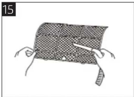
natural_image
Illustration of hands holding a woven mat with a tool, no text or symbols present
natural_image
Line drawing of a car air conditioner unit with handle and cooling fins (no text or symbols)TROUBLESHOOTING
WARNING!
You will not be able to remedy any faults with the air heat pump yourself. Incorrect repairs pose a risk of electric shocks and fire, and you should therefore contact a qualified service centre to get help.
You can however save both time and money by carrying out the following checks before you contact them.
| Problem Troubleshooting | |
| The air heat pump does not start. | The pump cannot start immediately after it has been turned off. This is a safety function. Wait approx. 3 minutes and then try to start the pump again. |
| Odours are emitted | Some odours may be emitted from the indoor unit. This is the result of room smells (such as furniture, tobacco, etc.) which have been sucked into the air heat pump and are being recirculated.Contact a qualified service centre to get assistance with more thorough cleaning if the odours persist for a long time. |
| Running water noise | When you hear a running waster noise, this is the refrigerant flowing in the air heat pump. |
| Mist is emitted in COOL mode | During the cooling operation, a thin mist may be seen emitted from the indoor unit due to high room temperature and humidity.After a while, the mist layer will disappear when the room has cooled down and dried out. |
| Cracking noise | This is the sound of friction caused by expansion and/or contraction of the panel or other parts due to the changes in temperature. It is entirely normal. |
| The air heat pump cannot be started | Is the power plug pulled out (if fitted)?Has the RCD triggered?Is the voltage too high/low? (Must be investigated by an electrician)Is the TIMER set correctly? |
| Cooling/heating gives poor results | ·Is the temperature setting correct? ·Is the inlet or outlet blocked? ·Is the filter dirty? ·Are windows or doors open? ·Is the fan set to a low speed? ·Are radiators or other heat sources turned on? |
| Remote control is not working | ·Check whether there is any magnetic or electrical interference near the air heat pump which could be affecting the remote control. If so, pull the plug out and put it back in. ·Is the remote control sufficiently close to the pump, or is the line of sight obscured? ·Check the batteries and replace them if necessary. ·Check whether the remote control is damaged. |
| Water is leaking from the indoor unit | ·Air humidity is high. ·Condensing water overflows. ·The drainage hose is loose. |
| Water is leaking from the outdoor unit | ·When the air conditioning is on, condensation will appear around pipes and pipe joints. ·Thawing water runs off during defrosting. ·During heating, water drips from the heat exchanger. |
| Noise coming from the indoor unit | ·Noise is emitted when the fan or compressor relays are turned or off. ·When defrosting starts and stops, noise will be emitted when the refrigerant runs into the unit. |
| No air is coming from the indoor unit | ·In HEAT mode, when the temperature of the indoor heat exchanger is very low, air flow is stopped in order to prevent cold air entering (within two minutes).·In heating (HEAT) mode, when the outdoor temperature is low or humidity is high, frost can form on the outdoor unit. The defrosting function starts automatically, and then the indoor unit stops blowing out air for 3-12 minutes.·During defrosting, water or vapour may be emitted.·In dehumidification (DRY) mode, the indoor fan will stop blowing out air for 3-12 minutes to avoid condensing water from becoming vaporised again. |
| Moisture on air outlet | If the air heat pump runs for a longer period while humidity is high, the grate over the air outlet could become damp and begin to drip. |
| C5: Fault with connector jumper | Check whether the jumper is making proper contact with the plug. If the PCB is to be replaced, use the jumper from the old PCB in the new one. |
| F1: Fault with the indoor temperature sensor | Check whether the indoor sensor is correctly connected. |
| F2: Fault with the evaporator's temperature sensor | Check if the temperature evaporator sensor is correctly connected. |
| H6: Indoor fan is blocked | ·Check if the indoor unit motor is connected correctly.·Replace the fan motor or PCB in the unit if they are faulty. |
| H1: Defrosting This is normal. | |
| The buttons on the cover are not working properly or at all | Check if the cover is closed properly. |
| · The air heat pump makes a noise during operation.· Strong odours are emitted during operation.· Water is leaking from the air heat pump.· The RCD or protection switch triggers too often.· Water or other liquids have entered one of the units.· The power cord or plug overheats. | Switch off the air heat pump and cut off the power supply. |
Installation check and start-up report
When installation is complete, an installation check should be carried out before the equipment is started. A copy of the report should be sent to Julia AB.
Customer
| Name: | |
| Address: | |
| Postal address: | |
| Telephone: | |
| Date: |
Product
| Model designation: | |
| Serial number of indoor component: | |
| Serial number of outdoor component: |
Operational data given at maximum fan speed:
| Air temperature indoor component (°C) | In (°C): | Out (°C): |
| Air temperature outdoor component (°C) | In (°C): | Out (°C): |
| Total electricity consumption (amps) | A | |
| Condensation temperature and pressure | (°C) | bar |
| Pipe length - one way | M | |
| Pressure pipe temperature | (°C) |
Started up by_
| Company: | |
| Address: | |
| Postal address: | |
| Telephone: | |
| Start-up date: | |
| F-gas certificate no.: | |
| Signature: | |
| Name: |
In order for the guarantee to be valid, a copy of this document must be sent by email to kundservice@jula.se or to Jula AB, Box 363, 532 24 Skara, Sweden.
1. Guarantee terms and conditions
General conditions
Dear Customer,
We would like to congratulate you on your choice of an Anslut air/air heat pump. The heat pump will reduce your heating costs and create a healthy and comfortable indoor environment all year round. The heat pump is built using the latest available technology for optimum performance, durability and comfort. The patented installation system allows for savings in the installation of the product.
Guarantee terms and conditions
Must be installed by a professional! In order for the guarantee to apply, proof of purchase is required to show that the hydronic heating system has been installed by a professional.
Under the Consumer Rights Act this product carries a 3 year guarantee against manufacturing defects when purchased for private use. We give a 5-year compressor guarantee and a 2-year guarantee on other parts. If you are making a claim for compensation under the guarantee, you must be able to produce proof of purchase, completed service documentation and proof to show that the product has been installed and used according to the information in the operating and installation instructions. In the event of a guarantee claim, you may be required to take the product to your nearest Julia store if repair on site can be considered excessively arduous for Julia (due to the fault type, location, road access, time expenditure, etc.).
A 1-year guarantee against manufacturing defects and a 5-year compressor guarantee are given for commercial operation. The owner of the business is responsible for ensuring compliance with legal and regulatory requirements.
It is important to read all the operating and installation instructions before starting installation.
Follow the instructions carefully, step by step. It is equally important that you read these operating instructions before putting the unit in operation. This is our guarantee in order for you to have confidence in the
product. We want you to be a satisfied user of your Anslut heat pump.
Service and service intervals
Service must be carried out regularly at least every other year. The first service must be carried out within one year of installation and the start of the unit. Note that the guarantees become void if service
has not been carried out.
Other conditions
According to a Julia approved professional assessment, faults constitute a departure from the normal standard. Faults or defects caused by abnormal effects, both mechanical and environmental, are not covered by this guarantee.
Jula is therefore not responsible for any faults caused by electrical surges or other electrical interference.
Neither is Julia liable for any faults due to failure to follow the installation and/or maintenance instructions.
Upon receipt of this product, it should be carefully examined. If faults are detected, they must be reported before using the product. In general faults must be reported immediately.
Jula reserves the right to make changes. In the event of problems, please contact our service department. www.jula.com
natural_image
Symbol of a trash bin crossed with no text or labels, representing waste sorting or disposal (no text present)Care for the environment!
Must not be discarded with household waste!
This product contains electrical or electronic components that should be recycled.
Leave the product for recycling at the designated station e.g. the clocal authority's recycling station.
- SVENSKA....6
- SÄKERHETSANVISNINGAR....6
- TEKNISKA DATA 8
- BESKRIVNING 9
- MONTERING....10
- Operation....117
- GENERAL INFORMATION AND TIpS....127
- SÄKERHETSANVISNINGAR
- INSTALLATIONSRITNING
- KONTROLL EFTER INSTALLATION SAMT FUNKTIONSTEST
- HANDHAVANDE
- KONTROLLERA FÖRE ANVÄNDNING
- OBS!
- Värna om miljön!
- INSTALLERE OG VEDLIKEHOLDE LUFTFILTERET
- Installere et nytt filter
- HåNDTERING
- KONTROLLER FøLGENDE Før BRUK
- FEILS∅KING
- ADVARSEL!
- KONTROLA PRZED UŻYCIEM
- UWAGA!
- Przycisk W LEWO / W PRAWO
- OSTRZEŻENIE!
- DBAJ O ŚRODOWISKO!
- Read the operating instructions carefully before use!
- WARNING!
- ASSEMBLy
- TO CONSIDER DURING INSTALLATION
- cHOOSING INSTALLATION SITE
- choosing indoor unit installation site
- choosing outdoor unit installation site
- SAFETy pRECAUTIONS FOR ELEcTRlCAL AppLIANcES
- NB:
- Earthing
- INSTALLATION DIAGRAM
- INSTALLATION OF INDOOR UNIT
- Installation of mounting bracket
- Drilling a hole for the pipe
- Installing the drainage hose
- Connect the indoor and outdoor electrical wires.
- Installing the connection pipe
- Laying the power cord
- Air purging and leakage test
- Outdoor condensation drainage (only for heat pump units)
- CHECK AFTER INSTALLATION AND FUNCTION TEST
- Check after installation
- 10
- Function test
- INSTALLATION AND MAINTENANCE OF THE AIR FILTER
- Installing a new filter
- OpERATION
- cHEcK BEFORE USE
- REMOTE CONTROL
- General use
- Other functions
- ON/OFF button
- MODE button
- FAN button
- TEMp button
- cLOcK button
- LIGHT button
- TURBO button
- X-FAN button
- + button
- - button
- QUIET button
- Up/DOWN button
- LEFT/RIGHT button
- TIMER ON button
- TIMER OFF button
- I FEEL button
- FLOW MODIFICATION butto
- SLEEp button
- In cooling mode (COOL)
- In heating mode (HEAT)
- DESCRIPTION OF SPECIAL FUNCTIONS
- About the X-FAN function
- About AUTO RUN mode
- About the TURBO function
- About the lock function
- About the UP/DOWN function
- About the LEFT/RIGHT function
- Switch between Celsius and Fahrenheit
- About the energy-saving function in cooling mode (COOL)
- About energy-saving mode in HEAT mode
- QUIET function
- Night mode function (SLEEp)
- Batteries
- Emergency operation
- AFTER USE
- GENERAL INFORMATION AND TIPS
- Cooling
- - Principle
- - Anti-freeze function
- Heating operation
- - Defrosting
- Energy-saving tips
- MAINTENANCE
- cLEANING AND cARE
- cleaning the front panel
- cleaning the air filter (every quarter)
- TROUBLESHOOTING
- Installation check and start-up report
- Guarantee terms and conditions
- General conditions
- Guarantee terms and conditions
- Service and service intervals
- Other conditions
- Care for the environment!
Brand : Anslut
Model : 416-117
Category : Air conditioner