USER MANUAL DEH-80PRS PIONEER
REPRODUCTOR DE CD CON RECEPTOR RDS
CD RDS-EMPFÄNGER
CD RDS-ONTVANGER
CD RDS ПРИЕМНИК
DEH-80PRS
Pioneer
Installation Manual
- When installing this unit in a vehicle without an ACC (accessory) position on the ignition switch, failure to connect the red cable to the terminal that detects operation of the ignition key may result in battery drain.

ACC position

No ACC position
- Use of this unit in conditions other than the following could result in fire or malfunction.
— Vehicles with a 12-volt battery and negative grounding.
— Speakers with 50 W (output value) and 4Ω to 8Ω (impedance value).
- To prevent a short-circuit, overheating or malfunction, be sure to follow the directions below.
— Disconnect the negative terminal of the battery before installation.
— Secure the wiring with cable clamps or adhesive tape. Wrap adhesive tape around wiring that comes into contact with metal parts to protect the wiring.
— Place all cables away from moving parts, such as the shift lever and seat rails.
— Place all cables away from hot places, such as near the heater outlet.
— Do not connect the yellow cable to the battery by passing it through the hole to the engine compartment.
— Cover any disconnected cable connectors with insulating tape.
— Do not shorten any cables.
— Never cut the insulation of the power cable of this unit in order to share the power with other devices. The current capacity of the cable is limited.
— Use a fuse of the rating prescribed.
— Never wire the negative speaker cable directly to ground.
— Never band together negative cables of multiple speakers.
- When this unit is on, control signals are sent through the blue/white cable. Connect this cable to the system remote control of an external power amp or the vehicle's auto-antenna relay control terminal (max. 300 mA 12 V DC). If the vehicle is equipped with a glass antenna, connect it to the antenna booster power supply terminal.
- Never connect the blue/white cable to the power terminal of an external power amp. Also, never connect it to the power terminal of the auto antenna. Doing so may result in battery drain or a malfunction.
- The black cable is ground. Ground cables for this unit and other equipment (especially, high-current products such as power amps) must be wired separately. If they are not, an accidental detachment may result in a fire or malfunction.
This unit
text_image
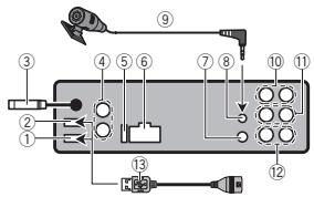
Diagram of a device rear panel with numbered components and labeled connectors
① USB port 1
② USB port 2
③ Antenna input 15 cm
④ Audio input
⑤ Fuse (10 A)
⑥ Power cord input
⑦ Wired remote input
Connections
Hard-wired remote control adaptor can be connected (sold separately).
⑧ Microphone input
⑨ Microphone
4 m
⑩ Rear output or high range output
⑪ Front output or middle range output
⑫ Subwoofer output or low range output
⑬ USB cable 1.5 m
- If connecting both USB1 (USB storage device1)/iPod1 (iPod connected using USB input1) and USB2 (USB storage device2)/iPod2 (iPod connected using USB input2) at the same time, use a Pioneer USB cable (CD-U50E) in addition to the regular Pioneer USB cable.
Power cord
flowchart
graph TD
    A["①"] --> B["②"]
    B --> C["③"]
    C --> D["④"]
    D --> E["⑤"]
    E --> F["⑥"]
    F --> G["⑦"]
    G --> H["⑧"]
    H --> I["⑨"]
    I --> J["⑩"]
    J --> K["⑪"]
    K --> L["⑬"]
    L --> M["⑭"]
    M --> N["⑮"]
    N --> O["⑯"]
    O --> P["⑰"]
    P --> Q["⑱"]
    Q --> R["⑲"]
    R --> S["⑳"]
    S --> T["㉑"]
    T --> U["㉒"]
    U --> V["㉓"]
    V --> W["㉔"]
    W --> X["㉕"]
    X --> Y["㉖"]
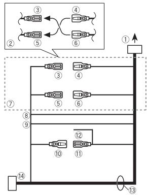
① To power cord input
② Depending on the kind of vehicle, the function of ③ and ⑤ may be different. In this case, be sure to connect ④ to ⑤ and ⑥ to ③.
③ Yellow
Back-up (or accessory)
④ Yellow
Connect to the constant 12 V supply terminal.
⑤ Red
Accessory (or back-up)
⑥ Red
Connect to terminal controlled by ignition switch (12 V DC).
⑦ Connect leads of the same color to each other.
⑧ Orange/white
Connect to lighting switch terminal.
⑨ Black (chassis ground)
⑩ Blue/white
The pin position of the ISO connector will differ depending on the type of vehicle. Connect ⑩ and ⑪ when Pin 5 is an antenna control type. In another type of vehicle, never connect ⑩ and ⑪.
⑪ Blue/white
Connect to system control terminal of the power amp (max. 300 mA 12 V DC).
⑫ Blue/white
Connect to auto-antenna relay control terminal (max. 300 mA 12 V DC).
13 Speaker leads
White: Front left ⊕ or middle range left ⊕
White/black: Front left ⊖ or middle range left ⊖
Gray: Front right ⊕ or middle range right ⊕
Gray/black: Front right ⊖ middle range right ⊖
Green: Rear left ⊕ or high range left ⊕
Green/black: Rear left ⊖ or high range left ⊖
Violet: Rear right ⊕ or high range right ⊕
Violet/black: Rear right ⊖ or high range right ⊖
Connections
⑭ ISO connector
In some vehicles, the ISO connector may be divided into two. In this case, be sure to connect to both connectors.
Power amp (sold separately)
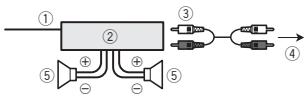
Standard mode with internal amp
Important
- Change the DSP switch to standard mode (STD).
For more details on change settings, refer to the operation manual or Switching the DSP setting mode on this page.
- The following signals are output from the speaker leads when this connection is in use.
White: Front left ⊕
White/black: Front left ⊖
Gray: Front right ⊕
Gray/black: Front right ⊖
Green: Rear left ⊕
Green/black: Rear left ⊖
Violet: Rear right ⊕
Violet/black: Rear right ⊖
flowchart
graph LR
    A["①"] --> B["②"]
    B --> C["③"]
    C --> D["④"]
    B --> E["⑤"]
    E --> F["+"]
    E --> G["-"]
    B --> H["+"]
    H --> I["-"]
    style A fill:#f9f,stroke:#333
    style B fill:#ccf,stroke:#333
    style C fill:#cfc,stroke:#333
    style D fill:#fcc,stroke:#333
    style E fill:#ffc,stroke:#333
    style F fill:#fcc,stroke:#333
    style G fill:#ffc,stroke:#333
    style H fill:#fcc,stroke:#333
① System remote control
Connect to Blue/white cable.
② Power amp (sold separately)
③ Connect with RCA cable (sold separately)
④ To subwoofer output
⑤ Subwoofer
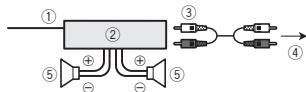
Standard mode without internal amp
Important
- Change the DSP switch to standard mode (STD).
For more details on change settings, refer to the operation manual or Switching the DSP setting mode on this page.
- If using this system, we recommend that this unit's internal amp is turned off.
For details, refer to the operation manual.
- The speaker leads are not used when this connection is in use.
flowchart
graph TD
    A["①"] --> B["②"]
    B --> C["③"]
    B --> D["④"]
    A --> E["⑤"]
    E --> F["⑥"]
    A --> G["⑦"]
    G --> H["⑧"]
    A --> I["⑨"]
    I --> J["⑩"]
    B --> K["⑤"]
    K --> L["⑥"]
    B --> M["③"]
    M --> N["④"]
    B --> O["⑦"]
    O --> P["⑧"]
    B --> Q["③"]
    Q --> R["④"]
    B --> S["⑤"]
    S --> T["⑥"]
    B --> U["③"]
    U --> V["④"]
    B --> W["⑤"]
    W --> X["⑥"]
    B --> Y["③"]
    Y --> Z["④"]
① System remote control
Connect to Blue/white cable.
② Power amp (sold separately)
③ Connect with RCA cable (sold separately)
④ To Rear output
⑤ Rear speaker
⑥ To Front output
⑦ Front speaker
⑧ To subwoofer output
⑨ Subwoofer
Connections
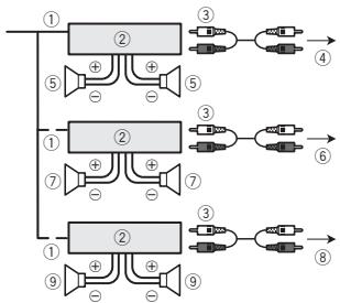
3-way network mode with internal amp
Important
- Change the DSP switch to 3-way network mode (NW).
For more details on change settings, refer to the operation manual or Switching the DSP setting mode on this page.
- The following signals are output from the speaker leads when this connection is in use.
White: Middle range left ⊕
White/black: Middle range left ⊖
Gray: Middle range right ⊕
Gray/black: Middle range right ⊖
Green: High range left ⊕
Green/black: High range left ⊖
Violet: High range right ⊕
Violet/black: High range right ⊖
flowchart
graph LR
    A["①"] --> B["②"]
    B --> C["③"]
    C --> D["④"]
    B --> E["⑤"]
    E --> F["+"]
    E --> G["-"]
    B --> H["+"]
    H --> I["-"]
① System remote control
Connect to Blue/white cable.
② Power amp (sold separately)
③ Connect with RCA cable (sold separately)
④ To low range output
⑤ Low range speaker
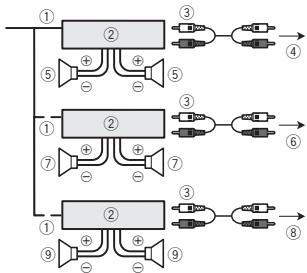
3-way network mode without internal amp
Important
-
Change the DSP switch to 3-way network mode (NW).
For more details on change settings, refer to the operation manual or Switching the DSP setting mode on this page.
-
If using this system, we recommend that this unit's internal amp is turned off.
For details, refer to the operation manual.
- The speaker leads are not used when this connection is in use.
flowchart
graph TD
    A["①"] --> B["②"]
    B --> C["③"]
    B --> D["④"]
    A --> E["⑤"]
    E --> F["⊕"]
    F --> G["⊕"]
    G --> H["⑤"]
    A --> I["①"]
    I --> J["②"]
    J --> K["③"]
    J --> L["⑥"]
    I --> M["⑦"]
    M --> N["⊕"]
    N --> O["⊕"]
    O --> P["⑦"]
    A --> Q["①"]
    Q --> R["②"]
    R --> S["③"]
    R --> T["⑧"]
    Q --> U["⑨"]
    U --> V["⊕"]
    V --> W["⊕"]
    W --> X["⑨"]
① System remote control
Connect to Blue/white cable.
② Power amp (sold separately)
③ Connect with RCA cable (sold separately)
④ To high range output
⑤ High range speaker
⑥ To middle range output
⑦ Middle range speaker
⑧ To low range output
⑨ Low range speaker
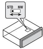
Switching the DSP setting mode
This unit features two operation modes: the 3-way network mode (NW) and the standard mode (STD). You can switch between modes as desired. Initially, the DSP setting is set to the standard mode (STD).
• After switching, reset the microprocessor.
Connections

WARNING
Do not use the unit in standard mode when a speaker system for 3-way network mode is connected to this unit. This may cause damage to the speakers.
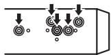
1 Use a thin, flathead screwdriver to change the DSP switch on the bottom of this unit.
text_image
STD NW
2 Press RESET with a pen tip or other pointed instrument.
For details, refer to the operation manual.
If you connect the unit to an audio device with RCA output, or to one with no RCA output, you can set it up so that the audio from the audio device is output through speakers connected to the unit. Change settings as necessary based on whether the connected device has RCA output or not.
For more details on change settings, refer to the operation manual or Switching between RCA input modes on this page.
If connecting the unit to a car stereo with RCA output
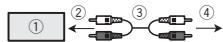
① Car stereo with RCA output
② To audio output
③ Connect with RCA cable (sold separately)
④ To audio input
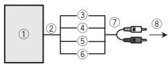
If connecting the unit to a car stereo with no RCA output
flowchart
graph LR
    ① --> ②
    ② --> ③
    ② --> ④
    ② --> ⑤
    ② --> ⑥
    ③ --> ⑦
    ④ --> ⑦
    ⑤ --> ⑦
    ⑥ --> ⑦
    ⑦ --> ⑧
① Car stereo with no RCA output
② To speaker output
③ Red: Right ⊕
④ Black: Right ⊖
⑤ Black: Left ⊖
⑥ White: Left ⊕
⑦ Speaker-RCA conversion cable (supplied) 19 cm
⑧ To audio input
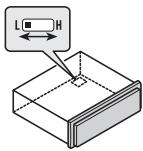
- Use a thin, flathead screwdriver to change the RCA input mode switch on the bottom of this unit.
text_image
L
H
- L (Low) - If inputting from the RCA output of a connected device
- H (High) - If inputting from the speaker output of a connected device
Installation

Important
- Check all connections and systems before final installation.
- Do not use unauthorized parts as this may cause malfunctions.
- Consult your dealer if installation requires drilling of holes or other modifications to the vehicle.
- Do not install this unit where:
— it may interfere with operation of the vehicle.
— it may cause injury to a passenger as a result of a sudden stop.
- The semiconductor laser will be damaged if it overheats. Install this unit away from hot places such as near the heater outlet.
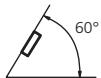
- Optimum performance is obtained when the unit is installed at an angle of less than 60^ .
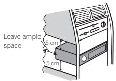
- When installing, to ensure proper heat dispersal when using this unit, make sure you leave ample space behind the rear panel and wrap any loose cables so they are not blocking the vents.
text_image
Leave ample
space
5 cm
5 cm
DIN front/rear mount
This unit can be properly installed using either front-mount or rear-mount installation.
Use commercially available parts when installing.
DIN Front-mount
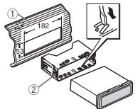
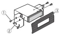
1 Insert the mounting sleeve into the dashboard.
For installation in shallow spaces, use the supplied mounting sleeve. If there is enough space, use the mounting sleeve that came with the vehicle.
2 Secure the mounting sleeve by using a screwdriver to bend the metal tabs (90°) into place.
text_image
Technical diagram showing assembly steps of a device with labeled components and dimensions
① Dashboard
② Mounting sleeve
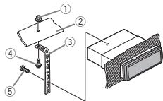
3 Install the unit as illustrated.
text_image
Technical diagram showing labeled mechanical components with numbered parts for identification
① Nut
② Firewall or metal support
③ Metal strap
④ Screw
⑤ Screw (M4 × 8)
Installation
■ Make sure that the unit is installed securely in place. An unstable installation may cause skipping or other malfunctions.
DIN Rear-mount
1 Determine the appropriate position where the holes on the bracket and the side of the unit match.
2 Tighten two screws on each side.
text_image
Technical diagram of an electronic component with labeled parts ①, ②, and ③
① Tapping screw (5 mm × 8 mm)
② Mounting bracket
③ Dashboard or console
Removing the unit
1 Remove the trim ring.
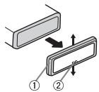
① Trim ring
② Notched tab
- Releasing the front panel allows easier access to the trim ring.
- When reattaching the trim ring, point the side with the notched tab down.
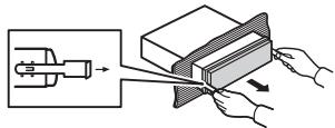
2 Insert the supplied extraction keys into both sides of the unit until they click into place.
3 Pull the unit out of the dashboard.
text_image
Diagram illustrating a mechanical or electrical process with labeled components and directional arrows indicating movement or transformation.
Removing and re-attaching the front panel
You can remove the front panel to protect your unit from theft.
Press the detach button and push the front panel upward and pull it toward you.
For details, refer to operation manual.
Installing the microphone
CAUTION
It is extremely dangerous to allow the microphone lead to become wound around the steering column or shift lever. Be sure to install the unit in such a way that it will not obstruct driving.
Note
Install the microphone in a position and orientation that will enable it to pick up the voice of the person operating the system.
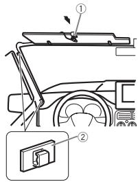
When installing the microphone on the sun visor
1 Install the microphone on the microphone clip.
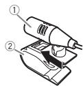
① Microphone
② Microphone clip
2 Install the microphone clip on the sun visor.
With the sun visor up, install the microphone clip. (Lowering the sun visor reduces the voice recognition rate.)
text_image
Technical diagram showing a vehicle's front-mounted panel assembly with labeled parts ① and ②
① Microphone clip
② Clamp
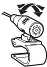
When installing the microphone on the steering column
1 Install the microphone on the microphone clip.
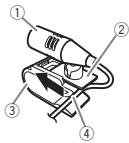
① Microphone
② Microphone base
③ Microphone clip
④ Fit the microphone lead into the groove.
- Microphone can be installed without using microphone clip. In this case, detach the microphone base from the microphone clip. To detach the microphone base from the microphone clip, slide the microphone base.
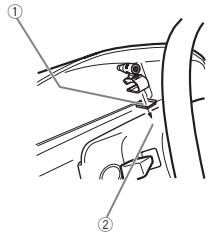
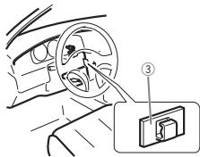
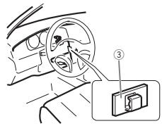
2 Install the microphone clip on the steering column.
text_image
Diagram showing car seatbelt mechanism with labeled parts ① and ②
text_image
Diagram showing car interior with steering wheel and device labeled ③, likely illustrating a steering or navigation system.
① Double-sided tape
② Install the microphone clip on the rear side of the steering column.
③ Clamp
Adjusting the microphone angle
The microphone angle can be adjusted.
Connexions

Important
text_image
Diagram of a device panel with numbered components and wiring connections
① Port USB 1
② Port USB 2
text_image
Technical diagram showing labeled components of a mechanical assembly with numbered parts
text_image
Technical diagram of a mechanical assembly with labeled components and directional arrows
natural_image
Diagram showing a mechanical device being processed into a layered block, with hands adjusting the component (no text or symbols present)
① Microphone
② Clip microphone
text_image
Diagram showing car interior components with numbered parts and a zoomed-in inset of the lower section.
text_image
Diagram showing car seatbelt mechanism with labeled parts ① and ②

text_image
Diagram showing car interior with steering wheel and labeled device panel (③)
text_image
Diagram of a device panel with numbered components and labeled connectors
text_image
Diagram of a multi-channel signal processing system with labeled components and connections
① Telecomando sistema
Collegare al cavo Blu/bianco.
text_image
Technical diagram showing labeled components of a mechanical assembly with numbered parts
Installazione
① Dado
② Paratia antifuoco o supporto in metallo
③ Staffa metallica
④ Vite
⑤ Vite (M4 × 8)
text_image
Technical diagram of a mechanical assembly with labeled components and directional arrows
natural_image
Illustration of hands cutting a rectangular block with a tool, showing mechanical assembly (no text or symbols)
text_image
Diagram showing car interior components with numbered parts and a zoomed-in view of the lower panel.
text_image
Diagram showing car seatbelt mechanism with labeled parts ① and ②

text_image
Diagram showing car interior with steering wheel and labeled device panel (③)
text_image
Diagram of a device panel with numbered components and wiring connections
text_image
Technical diagram showing labeled components of a mechanical assembly with numbered parts
① Tuerca
Instalación
② Muro cortafuego o soporte de metal
③ Correa metálica
④ Tornillo
⑤ Tornillo (M4 × 8)
text_image
Technical diagram of a device with labeled components and directional arrows indicating assembly or movement.
natural_image
Illustration of hands cutting a rectangular block with a tool, showing motion and assembly (no text or symbols)
text_image
Diagram showing car interior components with numbered parts and a zoomed-in view of the dashboard panel
① Pinza
② Abrazadera
text_image
Diagram showing car seatbelt mechanism with labeled parts ① and ②

text_image
Diagram showing car interior with steering wheel and labeled device panel (③)
text_image
Diagram of a device rear panel with numbered components and labeled connectors
① USB-Anschluss 1
② USB-Anschluss 2
text_image
Diagram of a multi-channel electronic device with labeled components and connections
text_image
Diagram of a signal processing or amplification system with labeled components and connections
text_image
Technical diagram showing assembly steps of a device with labeled components and dimensions
① Armaturenbrett
② Montagerahmen
text_image
Technical diagram showing labeled components of a mechanical assembly with numbered parts
text_image
Technical diagram of an electronic component with labeled parts and connection points
text_image
Diagram illustrating a mechanical or electrical process with labeled components and directional arrows indicating movement or transformation.
text_image
Diagram showing car interior components with numbered parts and a magnified inset of a device labeled '②'
① Mikrofonclip
② Klammer
text_image
Diagram showing car seatbelt mechanism with labeled parts ① and ②

text_image
Diagram showing car interior with steering wheel and device labeled ③, likely illustrating a steering or navigation system.
text_image
Diagram of a device panel with numbered components and labeled connectors
① USB-poort 1
② USB-poort 2
③ Antenne-ingang 15 cm
④ Audio-ingang
Verbindingen
text_image
Diagram of a multi-channel signal processing system with labeled components and connections
① Systeemafstandsbediening
text_image
Technical diagram showing labeled components of a mechanical assembly with numbered parts
① Moer
② Brandbescherming of metalen steun
③ Metalen strip
④ Schroef
Installatie
⑤ Schroef (M4 × 8)
text_image
Technical diagram of a mechanical assembly with labeled components and directional arrows
① Zelftappende schroef (5 mm × 8 mm)
② Bevestigingsklem
③ Dashboard of console
natural_image
Illustration of hands cutting a book from a mechanical component into a striped cover (no text or symbols)
text_image
Diagram showing car interior components with numbered parts and a magnified inset of a device labeled '1' and '2'.
① Microfoonklem
② Klem
text_image
Diagram showing car seatbelt mechanism with labeled parts ① and ②
text_image
Diagram showing car interior with steering wheel and labeled device panel (③)
text_image
Diagram of a device rear panel with numbered components and labeled connectors
text_image
Technical diagram showing assembly steps with labeled components and dimensions
text_image
Technical diagram showing labeled components of a mechanical assembly with numbered parts
text_image
Technical diagram of an electronic component with labeled parts and connection points
natural_image
Illustration of a mechanical device being processed into a layered block, with hands adjusting the component (no text or symbols present)
text_image
Diagram showing car interior components with numbered parts and a magnified inset of a device labeled '1' and '2'.
text_image
Diagram showing car seatbelt joint with labeled parts ① and ②

text_image
Diagram showing car interior with steering wheel and labeled component ③
PIONEER ELECTRONICS (USA) INC.
P.O. Box 1540, Long Beach, California 90801-1540, U.S.A.
TEL: (800) 421-1404
PIONEER EUROPE NV
Haven 1087, Keetberglaan 1, B-9120 Melsele, Belgium/Belgique
TEL: (0) 3/570.05.11
PIONEER ELECTRONICS ASIACENTRE PTE. LTD.
253 Alexandra Road, #04-01, Singapore 159936
TEL: 65-6472-7555
PIONEER ELECTRONICS AUSTRALIA PTY. LTD.
5 Arco Lane, Heatherton, Victoria, 3202 Australia
TEL: (03) 9586-6300
PIONEER ELECTRONICS OF CANADA, INC.
340 Ferrier Street, Unit 2, Markham, Ontario L3R 2Z5, Canada
TEL: 1-877-283-5901
TEL: 905-479-4411
PIONEER ELECTRONICS DE MEXICO, S.A. de C.V.
Blvd.Manuel Avila Camacho 138 10 piso
Col.Lomas de Chapultepec, Mexico, D.F. 11000
TEL: 55-9178-4270
先鋒股份有限公司
台北市內湖區瑞光路407號8樓
電話:886-(0)2-2657-3588
先鋒電子(香港)有限公司
香港九龍長沙灣道909號5樓
電話:852-2848-6488