
FH-P80BT - Car stereo PIONEER - Free user manual and instructions
Find the device manual for free FH-P80BT PIONEER in PDF.
| Product Type | Car Radio 1 DIN |
| Brand | Pioneer |
| Model | FH-P80BT |
| Dimensions (W x H x D) | 178 x 50 x 160 mm |
| Weight | Approximately 1.2 kg |
| Power Supply | 12 V DC (vehicle battery) |
| Power Consumption | Max. 10 A (10 A fuse) |
| Output Power | 50 W max per channel (4 Ω load) |
| Speaker Impedance | 4 Ω to 8 Ω |
| Main Functions | CD player, FM/AM tuner, Bluetooth hands-free, microphone input, voice control, IP-BUS |
| Connectivity | Front/rear/subwoofer outputs, microphone input, IP-BUS connector |
| Care and Cleaning | Clean with a soft dry cloth; do not use solvents |
| Safety | Professional installation required; observe polarity; do not block ventilation openings; use the correct fuse |
| Spare Parts and Repairability | Contact Pioneer after-sales service for any repairs |
| General Information | Car radio with Bluetooth hands-free kit; manual available online |
Frequently Asked Questions - FH-P80BT PIONEER
User questions about FH-P80BT PIONEER
0 question about this device. Answer the ones you know or ask your own.
Ask a new question about this device
Download the instructions for your Car stereo in PDF format for free! Find your manual FH-P80BT - PIONEER and take your electronic device back in hand. On this page are published all the documents necessary for the use of your device. FH-P80BT by PIONEER.
USER MANUAL FH-P80BT PIONEER
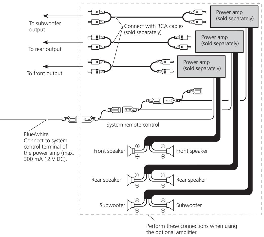
Connecting the units 2
Power cable connection. 4
Connecting to separately sold power amp. 6
Installation 8
Before installing this unit 8
Installation with the holder and side bracket 8
Installation using the screw holes on the side of the unit 9
Installing the microphone. 10
When installing the microphone on the sun visor 10
When installing the microphone on the steering column 10
Adjusting the microphone angle. 11
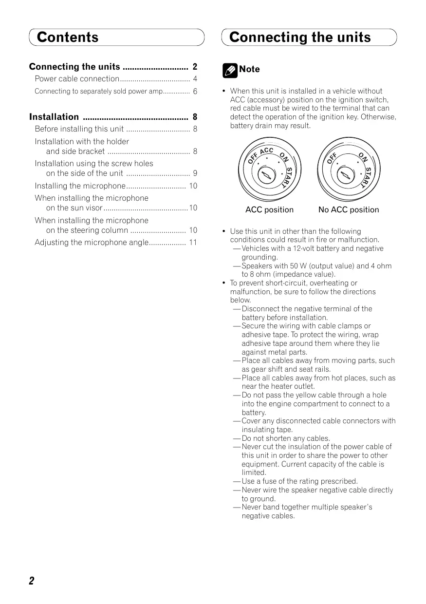
Connecting the units

Note
- When this unit is installed in a vehicle without ACC (accessory) position on the ignition switch, red cable must be wired to the terminal that can detect the operation of the ignition key. Otherwise, battery drain may result.

ACC position

No ACC position
- Use this unit in other than the following conditions could result in fire or malfunction.
—Vehicles with a 12-volt battery and negative grounding.
—Speakers with 50 W (output value) and 4 ohm to 8 ohm (impedance value).
-
To prevent short-circuit, overheating or malfunction, be sure to follow the directions below.
-
Disconnect the negative terminal of the battery before installation.
—Secure the wiring with cable clamps or adhesive tape. To protect the wiring, wrap adhesive tape around them where they lie against metal parts.
—Place all cables away from moving parts, such as gear shift and seat rails.
—Place all cables away from hot places, such as near the heater outlet. - Do not pass the yellow cable through a hole into the engine compartment to connect to a battery.
Cover any disconnected cable connectors with insulating tape.
—Do not shorten any cables.
—Never cut the insulation of the power cable of this unit in order to share the power to other equipment. Current capacity of the cable is limited.
—Use a fuse of the rating prescribed.
—Never wire the speaker negative cable directly to ground.
—Never band together multiple speaker's negative cables.
Connecting the units
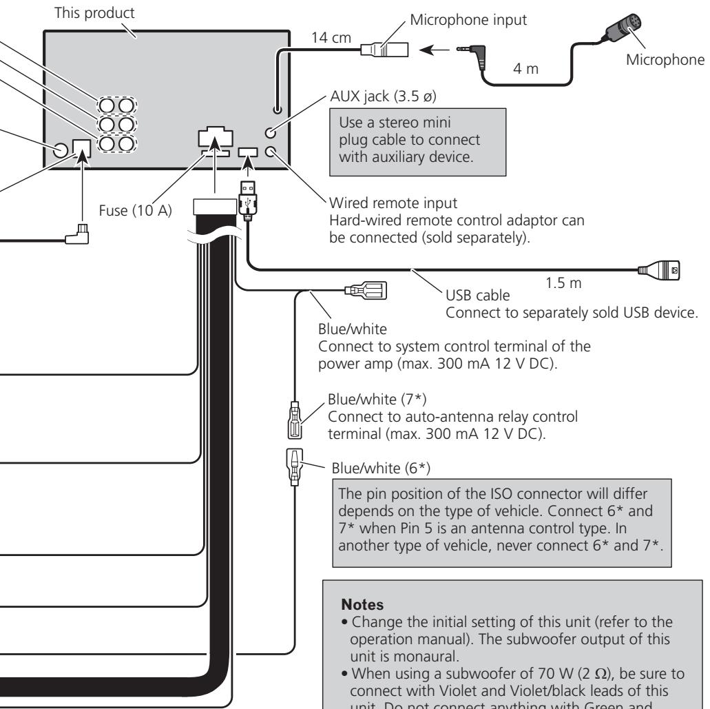
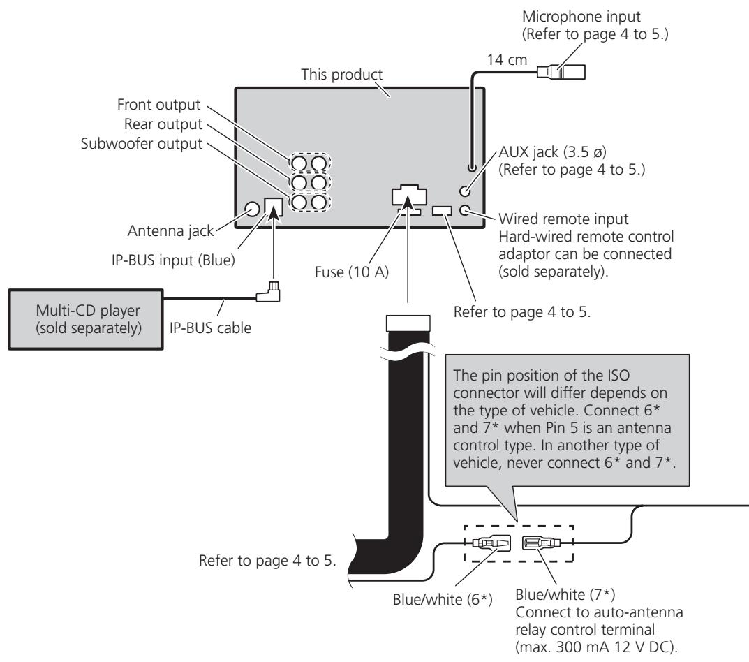
- Control signal is output through blue/white cable when this unit is powered on. Connect it to an external power amp's system remote control or the vehicle's auto-antenna relay control terminal (max. 300 mA, 12 V DC). If the vehicle is equipped with a glass antenna, connect it to the antenna booster power supply terminal.
- Never connect blue/white cable to external power amp's power terminal. Also, never connect it to the power terminal of the auto antenna. Otherwise, battery drain or malfunction may result.
- IP-BUS connectors are color-coded. Be sure to connect connectors of the same color.
- Black cable is ground. This cable and other product's ground cable (especially, high-current products such as power amp) must be wired separately. Otherwise, fire or malfunction may result if they are accidentally detached.
Connecting the units
Power cable connection
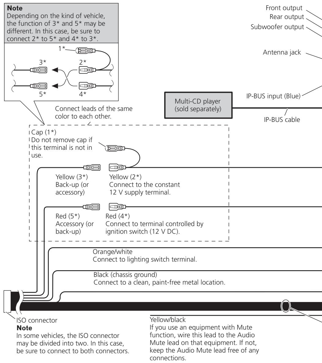
Speaker leads
White:
White/black:
Gray:
Gray/black:
Green:
Green/black:
Violet:
Violet/black:
Front left
Front left
Front right
Front right
Rear left or subwoofer
Rear left or subwoofer
Rear right or subwoofer
Rear right or subwoofer
Connecting to separately sold power amp
Installation

Note
- Check all connections and systems before final installation.
- Do not use unauthorized parts. The use of unauthorized parts may cause malfunctions.
- Consult with your dealer if installation requires drilling of holes or other modifications of the vehicle.
- Do not install this unit where:
- it may interfere with operation of the vehicle.
- it may cause injury to a passenger as a result of a sudden stop.
- Do not install the display where it may (i) obstruct the driver's vision, (ii) impair the performance of any of the vehicle's operating systems or safety features, including air bags, hazard lamp buttons or (iii) impair the driver's ability to safely operate the vehicle.
- The semiconductor laser will be damaged if it overheats. Install this unit away from hot places such as near the heater outlet.
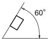
- Optimum performance is obtained when the unit is installed at an angle of less than 60^ .
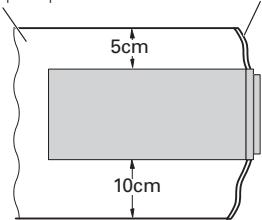
- When installing, to ensure proper heat dispersal when using this unit, make sure you leave ample space behind the rear panel and wrap any loose cables so they are not blocking the vents.
Leave ample space
Dashboard
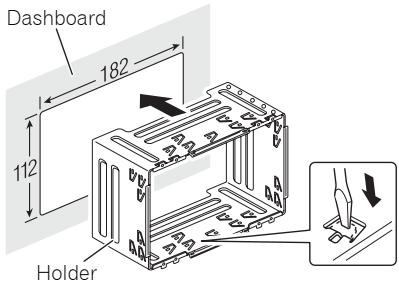
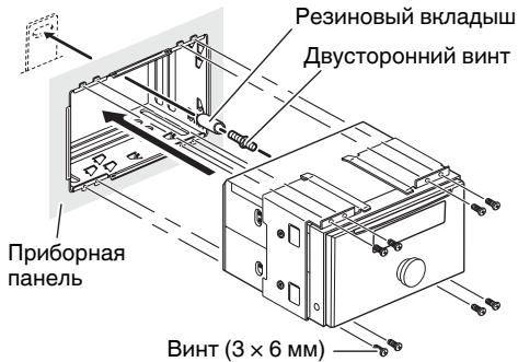
Before installing this unit
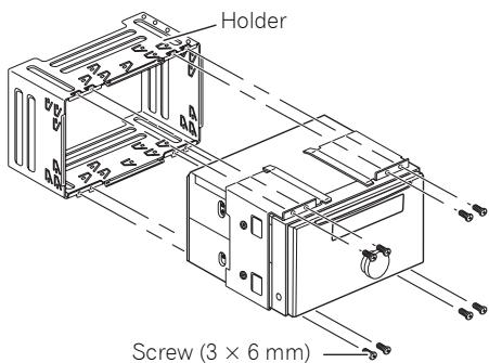
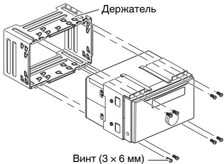
- Remove the holder.
Loosen the screws (3× 6mm) to remove the holder.
Installation with the holder and side bracket
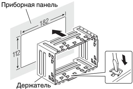
1. Install the holder into the dashboard.
After inserting the holder into the dashboard, select and bend the tabs appropriate to the thickness of the dashboard material. (Install this unit as firmly as possible using the top and bottom tabs. To secure this unit, bend the tabs 90 degrees.)
Installation
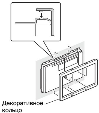
2. Install this unit and fasten the screws.
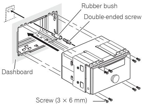
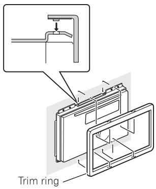
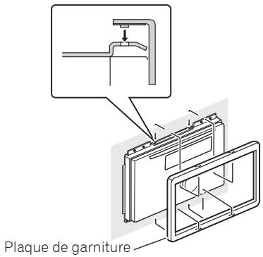
3. Attach the trim ring.
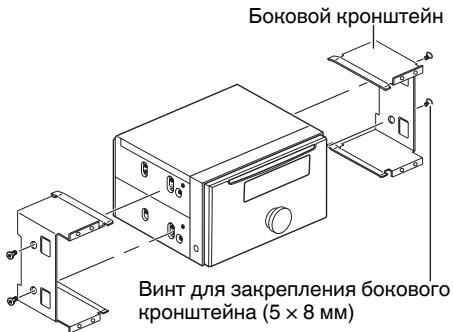
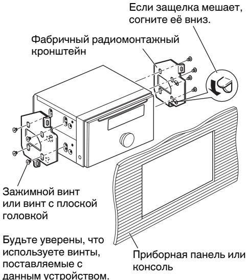
Installation using the screw holes on the side of the unit
1. Remove the side brackets.
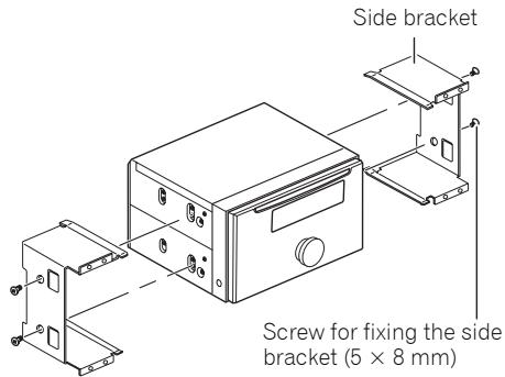
2. Fastening the unit to the factory radio-mounting bracket.
Position the unit so that its screw holes are aligned with the screw holes of the bracket, and tighten the screws at 3 or 4 locations on each side.
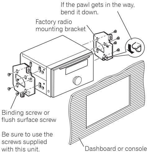

Note
In some types of vehicles, discrepancy may occur between the unit and the dashboard. If this happens, use the supplied frame to fill the gap.
Installation
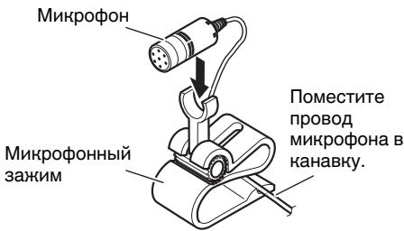
Installing the microphone
Installation notes
Install the microphone in a position and orientation that will enable it to pick up the voice of the person operating the system.

CAUTION
It is extremely dangerous to allow the microphone lead to become wound around the steering column or gearstick. Be sure to install the unit in such a way that it will not obstruct driving.
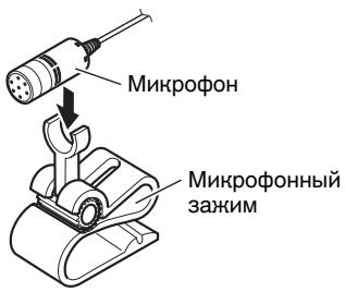
When installing the microphone on the sun visor
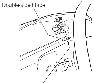
- Install the microphone on the microphone clip.
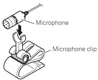
2. Install the microphone clip on the sun visor.
With the sun visor up, install the microphone clip. (Lowering the sun visor reduces the recognition rate for voice operations.)
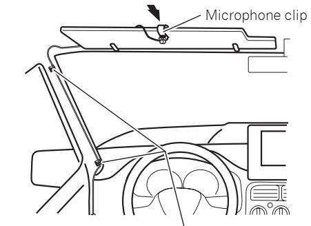
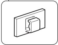
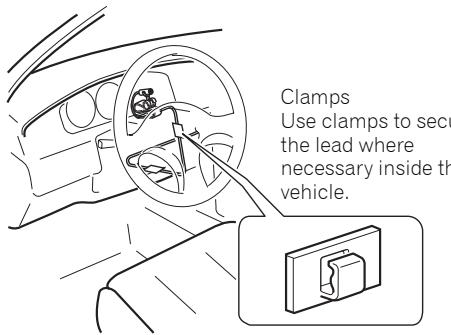
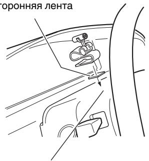
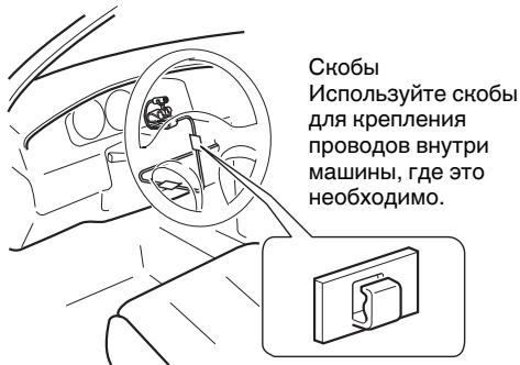
Clamps Use clamps to secure the lead where necessary inside the vehicle.
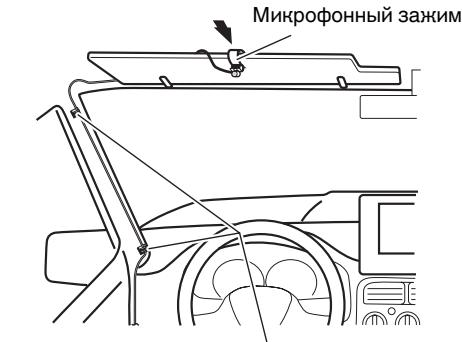
When installing the microphone on the steering column
- Install the microphone on the microphone clip.
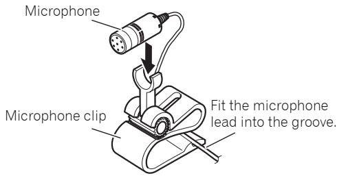
Installation
2. Install the microphone clip on the steering column.
Install the microphone clip on the rear side of the steering column.
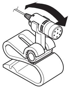
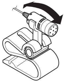
Adjusting the microphone angle
The microphone angle can be adjusted by moving forward or backward the microphone clip angle.
Contenido
- Retirez le support principal.
3. Attachez la plaque de garniture.
- ydaJIte depeHaTeIb
Ocna6bTe BnHTbI (3× 6MM) ,YTO6bl ydaHtB depKaTeIb
YcTaHOBbA C DepeHaTeJem N 60KOBbIM KpOHsTeHOM
1. YctahOBHTe DepeHateJIb B npn6OpHyIO nAHeIb.
Iocne yctaHOBNKn DepeKaTeJI B npi6bOpHyo naHeIb, Bbl6epnte H cOrHnte neTIn, COOTBETCTByUcNte ToLIIHe MaTePnaIa na6bOPHO n aHeI. (YcTaHOBHTe daHHoe yCTpoiCtBO KaK MOKHNo JeCTKO, HCNOJI3yB VerXHNe H NIKHNHe neTIn. YTO6bl oecnEnTb HndEJxHoCTb yCTaHOBKn yCTpoiCTBa, corHnte neTIn noD 90 rpaIycob.)
YctaHOBha
2. YctaHOBnTe daHoe yCTpoiCTBO n 3aTaNHTe BNHTbl.
3. Ппнренид ekopaTNBhoe HoIbco
YctaHOBNTe, HcNoJIb3yB BnHTOBbIe OTBepCTNa Ha CTopoHe yCTpoNCTBa
1. YdaJInte 6OHOBbIe KpOHTeiHbI.
2. 3aKpenIeHne yctpoIcTbAc a6pHbIM paHOMOHTaXHbIM KPOHTeHOM.
YcTaHOBnTe yCtpoCTBO TaK, YTObI eRO BVHTOBIIe OTBepCTNa COBnAaJIn C BHTOBbIMN OTBepCTmM KPOHUsTeHa, N 3aTAtHNe BVNTbI B 3 nIN 4 MecTaX Ha KaKnDo CTOpOHe.

Приимеане
B HeHOTopbIX MoDeJIaX TpaHCnOpTHbIX CpeDCTB MOnJE TpoN3OITn HecOoTBETCTBE MEnJy UcTPOIcTBOM IN PnIbOPHOI paHeJIbIO.EcIN 3TO PpON3IOET, IcNOJIb3yIte NoCTabJIeMyIO pAMHy, YTO6bI 3aONIHNTb 3a3Op.
YctaHOBha
YctaHObHa MHKpOfoHa
3aMeuHnno yctaHOBHe
UcTaHOBInTe MmKpOfoH B N03nCIO H opneHTnpuYte erO TaK, UTo6bI OH MOr yJnABnBaTb roLOc YeNoBeka, KOtOpbl OpePpyET CNTeMoI.
OCTOPOHHO
Upe3bUaHNo ONaCHO N03BOJATb npOBoDAMMHPOOHaO6OBBaTbC BOKpyr pyNeBoiKOLOHKn Hn PbYara NepeDaay. Y6eHNTecb, YTO UCTAOBUNYN UCTPOCTBO TAHM O6pa3OM, CTO OHO He 6ydet 3aTpdyHnTb DnHHeHne.
Korda MInKpoΦoH yctaHOBJIeH Ha cOJHcE3aUHTHom K03bIpbHe
- YctaHObHa MmKpOfoHa Ha MmKpOfoHHom 3aHHme.
2. YctaHObHa MmHPOfoHHoro 3aHIMHa coJIHcE3aUHTHom Ko3bIpbKe.
HabepycoIhue3aunTHoroKo3bipbka
yctahOBHTe MHpOfoHNb 3aXIM.
(OnyckaHne coIhue3aunTHoro Ko3bipbka
ymehbuaet cTeenb y3habnna
onepipyuope roJocA.)
Cbobl NcnoJIb3yIte Cbobl dIg KpeJIeHnI npOBoD8 BHyTnpMaJHbI, Ige 3TO HeO6XoIMo.
Korda MmHpoΦoH yCTaHOBJIeH Na pyJIeBOJ KOJOhKe
- YctaHObHa MmKpOfoHa Ha MmKpOfoHOM 3aXHMe.
YCTaHOBKa
2. YctaHOBHa MmHPOΦoHHORO 3aHIMa Ha pyJeBOH KOJOhKe.
Дыстороная Лемпа
YCTaHOBHTe MKNpOFOHHbI 3aHIM Ha 3aDHe CTOpOHe pyJeBOH KOLOHNKn.
PerylnpOBka yrla HaKloHa MmKpoΦoHa
YrOHa HAnHOHa MInKpOfoHa MoKeT
peRyIINPOBaTbC8 DBrNKeHHeM BpePeD IINI
Ha3aD MInKpOfoHHOro 3aKIma.
PIONEER CORPORATION
4-1, MEGURO 1-CHOME, MEGURO-KU
PIONEER ELECTRONICS (USA) INC.
P.O. Box 1540, Long Beach, California 90801-1540, U.S.A.
TEL: (800) 421-1404
PIONEER EUROPE NV
Haven 1087, Keetberglaan 1, B-9120 Melsele, Belgium
TEL: (0) 3/570.05.11
PIONEER ELECTRONICS ASIACENTRE PTE. LTD.
253 Alexandra Road, #04-01, Singapore 159936
TEL: 65-6472-7555
PIONEER ELECTRONICS AUSTRALIA PTY. LTD.
178-184 Boundary Road, Braeside, Victoria 3195, Australia
TEL: (03) 9586-6300
PIONEER ELECTRONICS OF CANADA, INC.
300 Allstate Parkway, Markham, Ontario L3R 0P2, Canada
TEL: 1-877-283-5901
TEL: 905-479-4411
PIONEER ELECTRONICS DE MEXICO, S.A. de C.V.
Blvd.Manuel Avila Camacho 138 10 piso
Col.Lomas de Chapultepec, Mexico, D.F. 11000
TEL: 55-9178-4270
先锋股份有限公司
總公司:台北市中山北路二段44號13樓
電話:(02) 2521-3588
先鋒電子(香港)有限公司
香港九龍尖沙咀海港城世界商業中心
9樓901-6室
電話:(0852)2848-6488
Published by Pioneer Corporation.
Copyright © 2007 by Pioneer Corporation.
All rights reserved.