
DEH-P8100BT - Car stereo PIONEER - Free user manual and instructions
Find the device manual for free DEH-P8100BT PIONEER in PDF.

| Brand | PIONEER |
| Model | DEH-P8100BT |
| Product type | Car stereo |
| Chassis type | DIN (front/rear mounting) |
| Power supply | 12 V DC, vehicle battery |
| Max output power | 50 W × 4 channels |
| Speaker impedance | 4 Ω - 8 Ω |
| Fuse | Specified value (see manual) |
| Player | CD |
| Radio | FM/AM |
| Bluetooth | Yes, for hands-free calling and audio streaming |
| Voice control | Yes, via built-in microphone |
| Remote control | Yes, wireless (steering wheel mount) |
| Microphone | Yes, external with sun visor or steering column mount |
| Supported audio formats | Audio CD, MP3, WMA (subject to confirmation) |
| Display | LCD screen |
| Connectivity | IP-BUS, audio inputs/outputs, antenna |
| Maintenance | Clean with a soft dry cloth, avoid solvents |
| Weight | Approximately 1.5 kg (estimate) |
| Dimensions (W × H × D) | Approximately 182 × 50 × 160 mm (standard DIN estimate) |
Frequently Asked Questions - DEH-P8100BT PIONEER
User questions about DEH-P8100BT PIONEER
0 question about this device. Answer the ones you know or ask your own.
Ask a new question about this device
Download the instructions for your Car stereo in PDF format for free! Find your manual DEH-P8100BT - PIONEER and take your electronic device back in hand. On this page are published all the documents necessary for the use of your device. DEH-P8100BT by PIONEER.
USER MANUAL DEH-P8100BT PIONEER
REPRODUCTOR DE CD CON RECEPTOR RDS
CD RDS-EMPFÄNGER
AUTORADIO CD RDS
SINTOLETTORE CD RDS
CD RDS-ONTVANGER
CD RDS ПРИЕМнИK
DEH-P8100BT
Installation Manual
Connecting the units 2
Connecting the power cord 4
When connecting to separately sold power amp. 6
Installation 8
DIN Front/Rear-mount. 8
Removing or attaching the trim ring. 8
DIN Front-mount 8
DIN Rear-mount 9
Installing the microphone. 9
When installing the microphone on the sun visor 9
When installing the microphone on the steering column. 10
Adjusting the microphone angle 10
Installing the steering remote control 10
Installing the unit on a left-hand drive car. 11
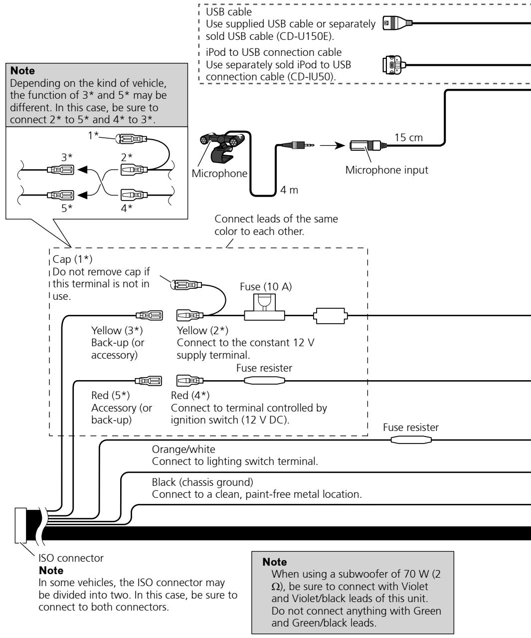
Connecting the units

Note
- When this unit is installed in a vehicle without ACC (accessory) position on the ignition switch, red cable must be wired to the terminal that can detect the operation of the ignition key. Otherwise, battery drain may result.
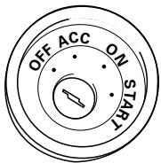
ACC position
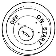
No ACC position
- Use this unit in other than the following conditions could result in fire or malfunction.
—Vehicles with a 12-volt battery and negative grounding.
—Speakers with 50 W (output value) and 4 ohm to 8 ohm (impedance value).
-
To prevent short-circuit, overheating or malfunction, be sure to follow the directions below.
-
Disconnect the negative terminal of the battery before installation.
—Secure the wiring with cable clamps or adhesive tape. To protect the wiring, wrap adhesive tape around them where they lie against metal parts.
—Place all cables away from moving parts, such as gear shift and seat rails.
—Place all cables away from hot places, such as near the heater outlet. - Do not pass the yellow cable through a hole into the engine compartment to connect to a battery.
Cover any disconnected cable connectors with insulating tape.
—Do not shorten any cables. - Never cut the insulation of the power cable of this unit in order to share the power to other equipment. Current capacity of the cable is limited.
—Use a fuse of the rating prescribed.
—Never wire the speaker negative cable directly to ground.
—Never band together multiple speaker's negative cables.
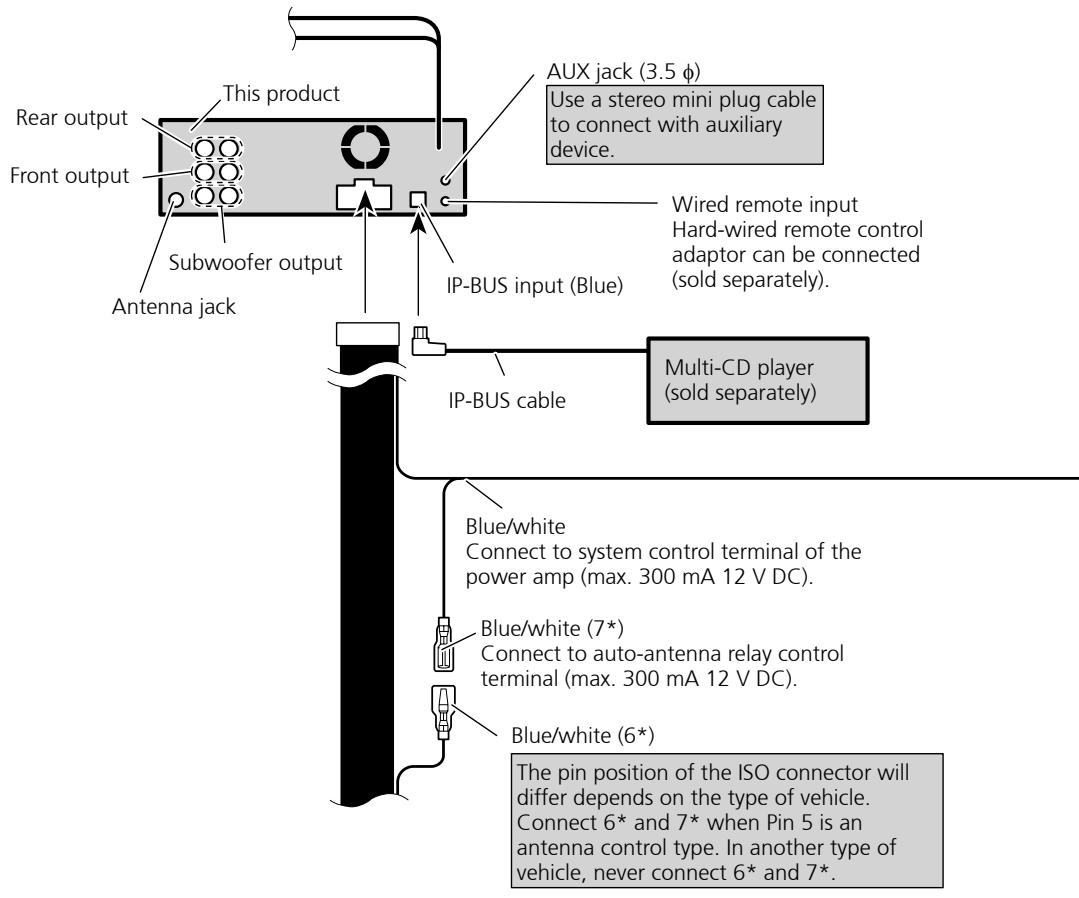
Connecting the units
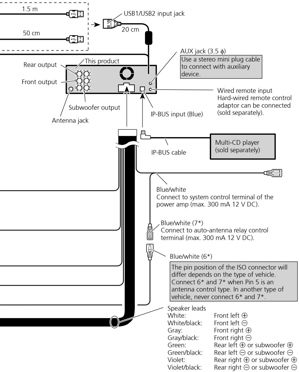
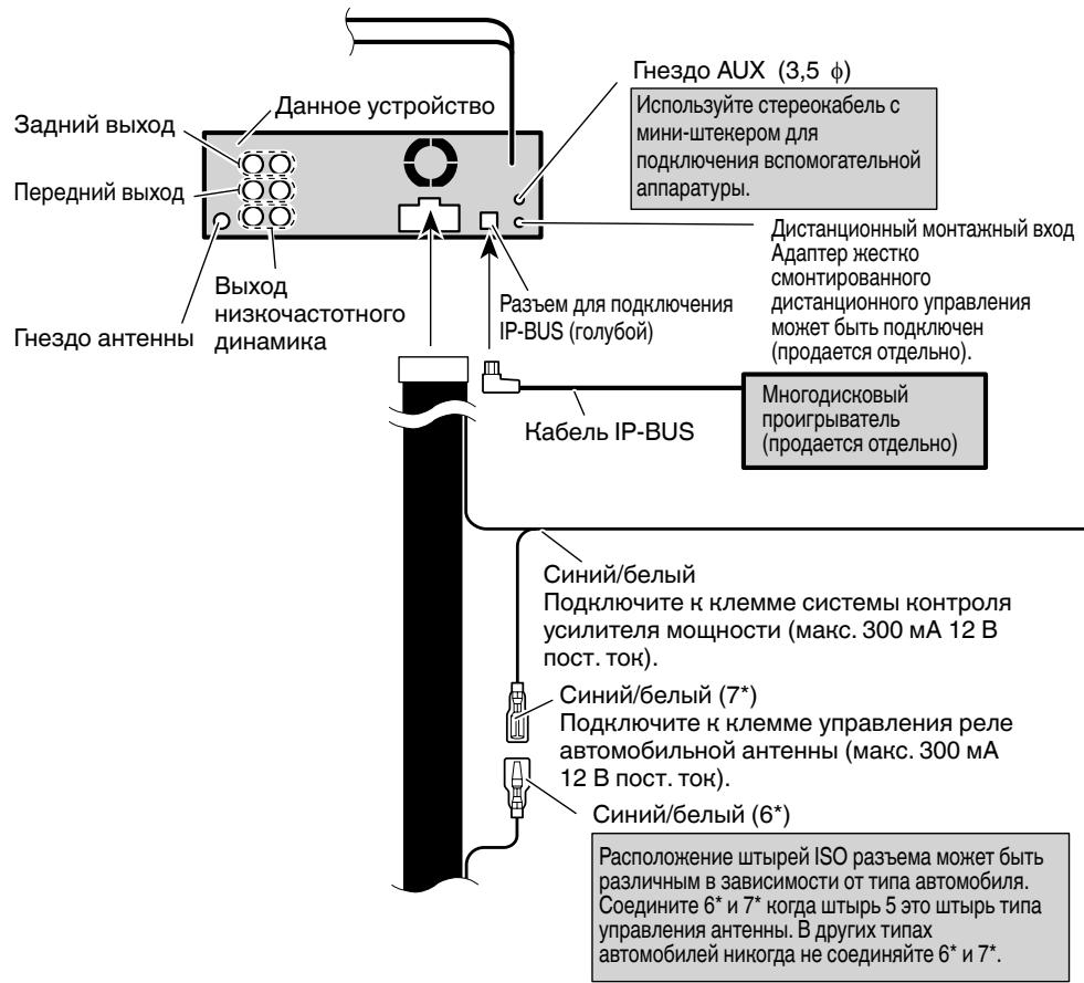
- Control signal is output through blue/white cable when this unit is powered on. Connect it to an external power amp's system remote control or the vehicle's auto-antenna relay control terminal (max. 300 mA, 12 V DC). If the vehicle is equipped with a glass antenna, connect it to the antenna booster power supply terminal.
- Never connect blue/white cable to external power amp's power terminal. Also, never connect it to the power terminal of the auto antenna. Otherwise, battery drain or malfunction may result.
- IP-BUS connectors are color-coded. Be sure to connect connectors of the same color.
- Black cable is ground. This cable and other product's ground cable (especially, high-current products such as power amp) must be wired separately. Otherwise, fire or malfunction may result if they are accidentally detached.
Connecting the power cord
Connecting the units
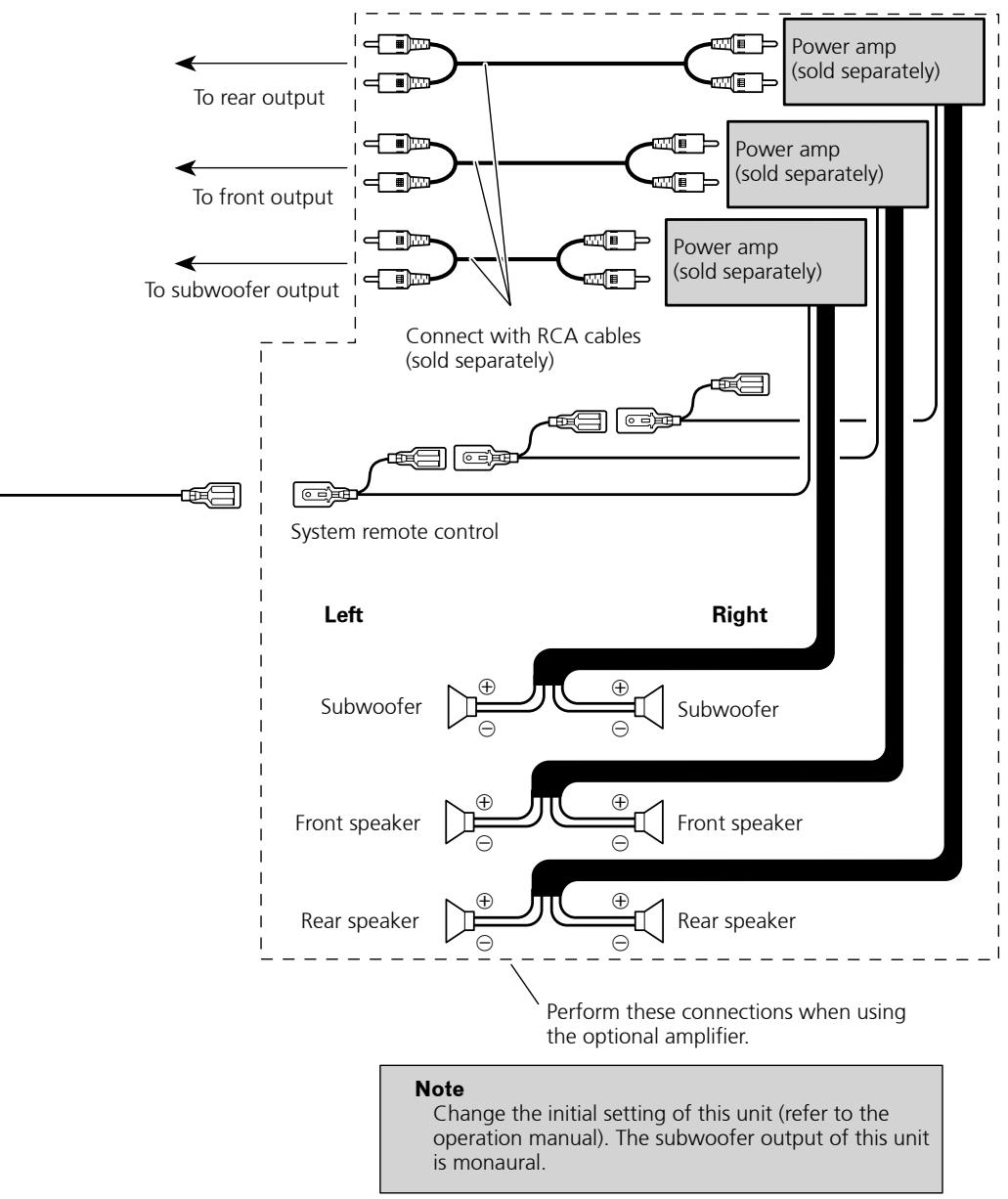
When connecting to separately sold power amp
Installation

Note
- Check all connections and systems before final installation.
- Do not use unauthorized parts. The use of unauthorized parts may cause malfunctions.
- Consult with your dealer if installation requires drilling of holes or other modifications of the vehicle.
-
Do not install this unit where:
-
it may interfere with operation of the vehicle.
it may cause injury to a passenger as a result of a sudden stop. -
The semiconductor laser will be damaged if it overheats. Install this unit away from hot places such as near the heater outlet.
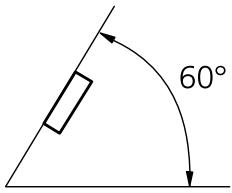
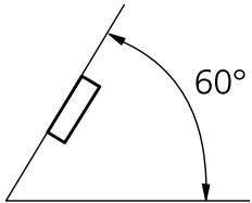
- Optimum performance is obtained when the unit is installed at an angle of less than 60^ .
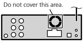
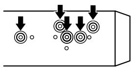
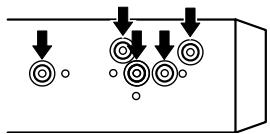
- When installing, to ensure proper heat dispersal when using this unit, make sure you leave ample space behind the rear panel and wrap any loose cables so they are not blocking the vents.
Leave ample space
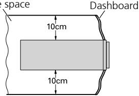
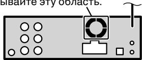
- The cords must not cover up the area shown in the figure. This is necessary to allow the amplifiers to radiate freely.
DIN Front/Rear-mount
This unit can be properly installed either from "Front" (conventional DIN Front-mount) or "Rear" (DIN Rear-mount installation, utilizing threaded screw holes at the sides of unit chassis). For details, refer to the following installation methods.
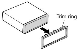
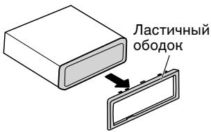
Removing or attaching the trim ring
-
Extend top and bottom of the trim ring outwards to remove the trim ring.
-
When reattaching the trim ring, push the trim ring onto the unit until it clicks. (If the trim ring is attached upside down, the trim ring will not fit properly.)
It becomes easy to remove the trim ring if the front panel is released.
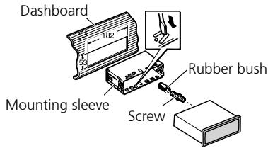
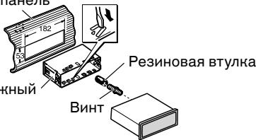
DIN Front-mount
Installation with the rubber bush
-
Insert the mounting sleeve into the dashboard.
-
When installing in a shallow space, use a supplied mounting sleeve. If there is enough space behind the unit, use factory supplied mounting sleeve.
- Secure the mounting sleeve by using a screwdriver to bend the metal tabs (90^) into place.
- Install the unit as illustrated.
Installation
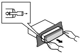
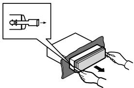
Removing the Unit
- Insert the supplied extraction keys into both sides of the unit until they click into place.
- Pull the unit out of the dashboard.
DIN Rear mount
- Determine the appropriate position where the holes on the bracket and the side of the unit match.
-
Tighten two screws on each side.
-
Use either truss screws (5 mm × 8 mm) or flush surface screws (5 mm × 9 mm), depending on the shape of screw holes in the bracket.
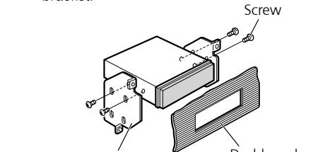
Factory radio mounting bracket
Console
Installing the microphone
Install the microphone in a position and orientation that will enable it to pick up the voice of the person operating the system.
CAUTION
- It is extremely dangerous to allow the microphone lead to become wound around the steering column or gearstick. Be sure to install the unit in such a way that it will not obstruct driving.
When installing the microphone on the sun visor
- Install the microphone on the microphone clip.
-
Install the microphone clip on the sun visor.
-
With the sun visor up, install the microphone clip. (Lowering the sun visor reduces the voice recognition rate.)
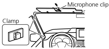
- Use separately sold clamps to secure the lead where necessary inside the vehicle.
Installation
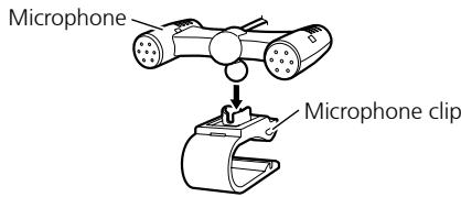
When installing the microphone on the steering column
1. Install the microphone on the microphone clip.
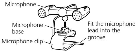
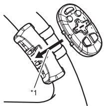
- Microphone can be installed without using microphone clip. In this case, detach the microphone base from the microphone clip. To detach the microphone base from microphone clip, slide the microphone base.
2. Install the microphone clip on the steering column.
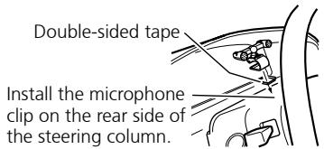
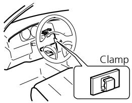
- Use separately sold clamps to secure the lead where necessary inside the vehicle.
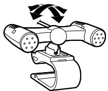
Adjusting the microphone angle
The microphone angle can be adjusted.
Installing the steering remote control

WARNING
- Avoid installing this unit in such a location where the operation of safety devices such as airbags is prevented by this unit. Otherwise, there is a danger of a fatal accident.
- Avoid installing this unit in such a location where the operation of the steering wheel and the gearshift lever may be prevented. Otherwise, it may result in a traffic accident.

CAUTION
- Installation of this unit requires specialized skills and experience. Installation of this unit should be entrusted to a dealer from whom you purchased this unit.
- Install this unit using only the parts supplied with this unit. If other parts are used, this unit may be damaged or could dismount itself, which leads to an accident or trouble.
- Install this unit as required by this manual. Failure to do so may cause an accident.
- Do not install this unit near the doors where rainwater is likely to be spilled on the unit. Incursion of water into the unit may cause smoke or fire.

WARNING
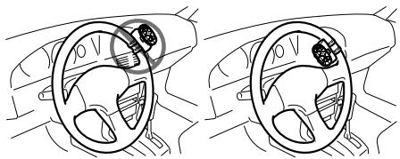
Fix this unit securely to the steering wheel with the belt attached to the unit. If this unit is loose, it disturbs driving stability, which may result in a traffic accident.
- Do not attach this unit to the outer circumference of the steering wheel. Otherwise, it disturbs driving stability, causing a traffic accident. Always attach this unit to the inner circumference of the steering wheel as shown.
Installation

Note
- Do not install this unit in such a place as may obstruct the driver's view.
- Since interior layout differs depending on the type of vehicle, the ideal installation location for the unit also differs. When installing the unit, select a location that assures optimum transmission of signals from the unit to the car stereo.
Installing the unit on a left-hand drive car

Note
- When the unit is installed on a right-hand-drive car, the horizontal positions are inverted.
1. Hook the belt on to the holder.
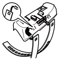
2. Fix the holder to the inside edge of the steering wheel so that the holder is facing the driver.
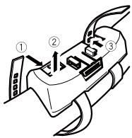
- ①② Wrap the belt around the outside edge of the steering wheel, passing the end through the slot in the holder.
③ Pull on the belt to tighten it then secure it using the other two hooks on the holder.
3. ④ Cut off the extra portion of the belt.
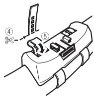
- (5) If some of the belt still protrudes, fold it back into the slot so that it does not interfere with driving.
4. Fasten the other belt in the same way.
5. Install the remote control unit in the holder.
- When removing the remote control unit from the holder, move the corrugated release section toward the steering wheel and slide the remote control unit toward you.
Contenido
CoeHHeNc yCnHtTeIeM MoUHOCTN, KOToPbI npOdaeTcR OTeJIbHo. 6
YctaHOBka 8
IpeaHHe/3aHHee KpeJIeHne no cTaNdApTy DIN 8
YdaJIeHHe HnI npKpeJIeHne IaCTNHyHO 6oDka. 8
Ipeedhe Kpenenne no cTaNapTy DIN .... 8
3aDHee KpeIeHne no cTaHapTy DIN. 9
YcTaHOBka MmKpofoHa. 9
Korda MmKpOfoH ycTaHOBJIeH Ha coJIHcE3aUHTOM KO3bIpbKe 9
Korda MInKpOfoH ycTaHOBJIeH ha pyJbeoI KOJOnHe 10
Perynipobka yrla haKloha mKnpofoha. 10
UcTaHOBbYcTpoNCTBaIncTaHcNoHHOrO UnpaBHeHnHa PyJe 10
UcTaHOBbA yCtPoIcTBA Ha aBTOMO6nIax C neBbIM pynBeBIM uypaBHeHm KOJeC. 11
CoéniHene c yucnltelem MOUHOCTN, HOTOpbI npOdaetc r OTdJIbHo
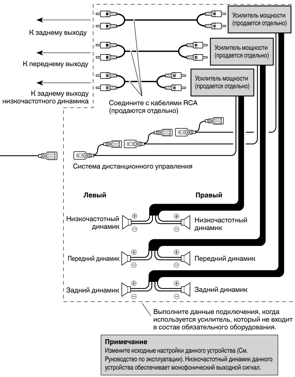

Примechане
- PIOBOpBeTe BCE COeHNHeHnI CnCTeMbI nepeD OKOHaTeJIbHOY YCTaHOBKOI.
He nCnoJb3yTe Hepa3peHEnHbIe qactN. NcNoJIb3OBAHnE Hepa3peHbXbACTeMy MoJcET CTaTB pNCHNO HeNCnpABNO pa60TbI. - PpokohcylbTnpuyTebcBaWIMdHJepom, eLmYcTaHOBkA Tpe6yeT pOcBepnVBaHHN OTBepCTN INIpyrNX MoDnΦnKaun BaWero TpaHCnOpTHOro CpeCDtBA.
- He yctanabHnBaTyeCTpoiCTBO TAm, rge: - OHO MOKeT cIyHHTb npEnTCTBHe m paObToI TpaHCNOpTHOro cpeDCTBa.
- OHO MOKeT cTaB npMnHNOBpeKdEHH naCaxHpa Bpe3yIbTaTe BHe3aHNOH OCTaHOBKN.
- PólynpoBODHnHObI JIa3ep 6ydeT NOBpeKdE, eJN OH nepePeeTc. YCTaHAbJIbAe TdaHNoe yCtpoiCTBO BVaIIT O rOpayHx MeT, TaHx KaH pHDM C BByNcHOM HarpeBaTeN.
- OTHMAbHoe IN360paJxHe HNe NOJyuaTeCn, KOrDa YcTPOCTBO YcTaHOBJeHO NOd YrIOM MeHbSeYem 60°.
- PnycTaHOBKe, nOcLe nOdTBePckDeHnnaNDxOJaIeFo paCCBbAHN TEnla npriNCIOJIb3ObAHm 3TOy UcTObCTBA, NOXaJNyCTa, yDooCTOBpeTbC, YTO BbIOCTABJNeTe IPOCTPHoe MecTo N03aIaN aDneNaHeJI N, NOXaJNyCTa, CBePNTE LIObIe HENpIKpeJIeHNbIe KAbEJI TaK, YTObJI OHNHe CMOrJI 3aBLOKnIPoBaTb BEHTUNLAIOHHOETOBepCTNe.
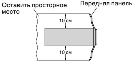
- PpOBoJa He DoJIHHbI 3aKpbIbTaB 30HbI, nOKa3aHHbI Ha pICyHKe. 3To Heo6XoIMo dIra CBO6OHOr o paCCeINBaHnIe TepIIa, nIlyuAeMOr OyCNlTeJAMn.
He 3aKpbIbaiTe 3Ty o6JIacTb.
IpeedHee/3aDHee KpeJIenHeNo cTaHdApTy DIN
KpeIeHne daHHoro ycTpoiCTBa MOHO BbIOJIHrTb KaK "CpeEaN" (CTaHdAptHoe nepeIeHne KpeIeHne DIN), TaK n "C3aDn" (3aHNe KpeIeHne DIN c IcNoJ3OBAHNm pe3bOobx IOBETpcTn Ira BnHTOB, paCNOJIOKeHHbx NO 6OKAM pAmbl yctPoIcTBA).
Bolee noipob6hna HnΦopMaun npuBvEHa HnHex B nIIOCTpnpoBaHOM OINCaHm MeTODOb yCTaHOBKn.
YdaJIeHne HnnpKpeIeHne JIactNCHoro 06OJa
- OTTAHNTe Bepx Hn3 JIaCTHNOHO 06oHa HApKy, YTO6bI BBItaunlt bero.
Korda noBtOpHNo npncOeDnHReTe nactuHbI O6oDok, BdABHTe erO B yCTPOiCTBO, nOKa OH He 5eJIKNHeT. (EcIn nactuHbI O6oDok npncOeDnHcBepxHcN CTOPHOHN3, TO OH He 6yDet NODOrHaNd D0JHXbIM O6pa3OM.)
- BbItaunTb IacTnHbI oOdoK IerYe, eCIn npeednaHeIb onyueHa.
IpeedHee KpenJleHne no cTaNdapTy DIN
YctaHOBcpe3HHOBB BtJH0
- BctabbTe MOHTaHHbI pyHAb B nepeDHIO nHeJIb.
Korda yctahablnBaeteB HeRny60KepeoCtpaHCTBO, nCnOlb3yIte npEyCMOTpeHHb moHTaxHHb pyKAB. EcnI no3aDi yctpoiTcBA MeeTcA DoCTaTOHoe npocCTpaHCTBO, nCnOlb3yIte npEyCMOTpeHHb 3aBoDM MOHTaXHHb pyKAB.
2.3aKpennTe MOHTaHHbI pyHAB, HcNoJIb3yI OTBepTHy, YTO6bl COrHytMeTaJIHueChne yuHn (90°) Ha MeCTO. - YctaHOBHTe yCTpoIcTBO HAK ONaHaHO Ha HJIIOCTpaunn.
PepednnaheB
YdaJIeHne YcTpoIcTBa
- BctabBeI npedymOTpeHbIe KIOUd IaN3BLeueHnB O6e CTOpOHbI yCTpOJCTBa, NOKA OHn He 3aUeJIKNHyTcR Ha MeCTO.
- BbITaHInTe yCTpOiCTBO n3 nepeDne nnHeJI.
3aДпсгрелене no cTaHdapTy DIN
1.Подберпге похоршемсто, rde OTberpctnaHa cho6e n CTopohe yctpoiCTBa 6ydyT coBnadaTb.
2. 3aTaNHTe Dba BnHTa Ha KaHDoI CTopoHc.
4-1, MEGURO 1-CHOME, MEGURO-KU
PIONEER ELECTRONICS (USA) INC.
P.O. Box 1540, Long Beach, California 90801-1540, U.S.A.
TEL: (800) 421-1404
PIONEER EUROPE NV
Haven 1087, Keetberglaan 1, B-9120 Melsele, Belgium/Belgique
TEL: (0) 3/570.05.11
PIONEER ELECTRONICS ASIACENTRE PTE. LTD.
253 Alexandra Road, #04-01, Singapore 159936
TEL: 65-6472-7555
PIONEER ELECTRONICS AUSTRALIA PTY. LTD.
178-184 Boundary Road, Braeside, Victoria 3195, Australia
TEL: (03) 9586-6300
PIONEER ELECTRONICS OF CANADA, INC.
300 Allstate Parkway, Markham, Ontario L3R OP2, Canada
TEL: 1-877-283-5901
TEL:905-479-4411
PIONEER ELECTRONICS DE MEXICO, S.A. de C.V.
Blvd. Manuel Avila Camacho 138 10 piso
Col.Lomas de Chapultepec, Mexico, D.F. 11000
TEL: 55-9178-4270
先锋股份有限公司
總公司:台北市中山北路二段44號13樓
電話:(02)2521-3588
先鋒電子(香港)有限公司
香港九龍尖沙咀海港城世界商業中心
9樓901-6室
電話:(0852) 2848-6488
Published by Pioneer Corporation.
Copyright © 2009 by Pioneer Corporation.
All rights reserved.