AVIC-X1 - GPS Navigation System PIONEER - Free user manual and instructions
Find the device manual for free AVIC-X1 PIONEER in PDF.

| Brand | PIONEER |
| Model | AVIC-X1 |
| Category | GPS navigation system |
| Product type | Car navigation system with LCD screen |
| Power supply | 12 V DC (vehicle battery, negative ground) |
| Fuse | Replace with a fuse of the same rating (see fuse holder) |
| Main functions | GPS navigation, voice guidance, DVD/CD playback, radio, video input/output, rear view camera (optional), voice recognition (optional) |
| Inputs | AV-IN (RCA), speed signal input, reverse gear input, microphone input (optional) |
| Outputs | Front, rear, subwoofer output (mono), rear video output, audio output, guidance output |
| Connections | IP-BUS, AV-BUS, 30-pin cable, extension port |
| GPS antenna | Supplied, magnetic mount, indoor or outdoor installation |
| Supplied parts | Power cord, connector, extension cords (speed signal, reverse, antenna), side brackets, rings, screws, wire ties, waterproof pad, metal plate |
| Safety | Professional installation recommended; do not use while driving (except navigation); do not obstruct airbags |
| Operating temperature | Avoid high temperatures and humidity (near heater, direct sunlight) |
| Speaker compatibility | Max power 50 W per channel, impedance 4-8 ohms |
| Remote unit model number | AVIC-X1 (display unit + remote unit) |
| Maintenance | Have maintenance done by a professional; do not disassemble |
Frequently Asked Questions - AVIC-X1 PIONEER
User questions about AVIC-X1 PIONEER
0 question about this device. Answer the ones you know or ask your own.
Ask a new question about this device
Download the instructions for your GPS Navigation System in PDF format for free! Find your manual AVIC-X1 - PIONEER and take your electronic device back in hand. On this page are published all the documents necessary for the use of your device. AVIC-X1 by PIONEER.
USER MANUAL AVIC-X1 PIONEER
This product conforms to new cord colours.
ABOUT YOUR NEW NAVIGATION SYSTEM AND THIS MANUAL
- The navigation features of this unit (and rear view camera option if purchased) is intended solely as an aid to you in the operation of your vehicle. It is not a substitute for your attentiveness, judgement and care when driving.
- Never use this Navigation System to route to hospitals, police stations, or similar facilities in an emergency, Please call the appropriate emergency number.
- Do not operate this Navigation System (or the rear view camera option if purchased) if doing so in any way will divert your attention from the safe operation of your vehicle. Traffic restrictions and advisories currently in force should always take precedence over guidance given by this product. Always obey current traffic restrictions, even if this product provides contrary advice.
- This manual explains how to install this Navigation System in your vehicle. Operation of this Navigation System is explained in the separate “Operation Manual” or “Hardware Manual” for Navigation System.
- Do not install the display unit or Hide-away unit where it may (i) obstruct the driver's vision, (ii) impair the performance of any of the vehicle's operating systems of safety features, including airbags, hazard lamp buttons or (iii) impair the driver's ability to safely operate the vehicle. In some cases, it may not be possible to install this unit because of the vehicle type or the shape of the vehicle interior.
IMPORTANT INFORMATION .... 1
ABOUT YOUR NEW NAVIGATION SYSTEM AND THIS MANUAL .... 1
IMPORTANT SAFEGUARDS .... 3
PLEASE READ ALL OF THESE INSTRUCTIONS REGARDING YOUR NAVIGATION SYSTEM AND RETAIN THEM FOR FUTURE REFERENCE .... 3
Connecting the System 4
● Before installing the unit
● To prevent damage
- Parts supplied
Connecting the system 7
Connecting the power cord (1) 9
Connecting the power cord (2) 11
When connecting to separately sold power amp 13
When connecting with a Rear view camera 15
When connecting the external video component and the display .... 16
- When using a display connected to rear video output
Installation 17
To guard against electromagnetic interference 18
Before installing 18
Installing the display unit and Hide-away unit 19
● Installation notes
- Parts supplied
● Installing the Hide-away unit
● DIN Front/Rear-mount
● DIN Front-mount
- DIN Rear-mount
● Fixing the front panel
Installing the GPS aerial 26
● Installation notes
- Parts supplied
- When installing the aerial inside the vehicle (on the rear shelf)
- When installing the aerial outside the vehicle (on the body)
After Installing the Unit ......29
PLEASE READ ALL OF THESE INSTRUCTIONS REGARDING YOUR NAVIGATION SYSTEM AND RETAIN THEM FOR FUTURE REFERENCE
- Read this manual fully and carefully before installing your Navigation System.
- Keep this manual handy for future reference.
- Pay close attention to all warnings in this manual and follow the instructions carefully.
- This Navigation System may in certain circumstances display erroneous information regarding the position of your vehicle, the distance of objects shown on the screen, and compass directions. In addition, the system has certain limitations, including the inability to identify one-way streets, temporary traffic restrictions and potentially unsafe driving areas. Please exercise your own judgement in the light of actual driving conditions.
- As with any accessory in your vehicle's interior, the Navigation System should not divert your attention from the safe operation of your vehicle. If you experience difficulty in operating the system or reading the display, please make adjustments while safely parked.
- Please remember to wear your seat belt at all times while operating your vehicle. If you are ever in an accident, your injuries can be considerably more severe if your seat belt is not properly fastened.
- Certain countries laws may restrict the placement and use of Navigation Systems in your vehicle. Please comply with all applicable laws and regulations in the installation and operation of your Navigation System.
WARNING
Do not attempt to install or service your Navigation System by yourself. Installation or servicing of the Navigation System by persons without training and experience in electronic equipment and automotive accessories may be dangerous and could expose you to the risk of electric shock or other hazards.
WARNING
- Pioneer does not recommend that you install your Navigation System yourself. We recommend that only authorised Pioneer service personnel, who have special training and experience in mobile electronics, set up and install the unit. NEVER SERVICE THE UNIT YOURSELF. Installing or servicing the unit and its connecting cables may expose you to the risk of electric shock or other hazards, and can cause damage to the Navigation System that is not covered by warranty.
CAUTION
- If you decide to perform the installation yourself, and have special training and experience in the mobile electronics installations, please carefully follow all of the steps in the Installation Manual.
- Secure all wiring with cable clamps or electrical tape. Do not allow any bare wiring to remain exposed.
- Do not directly connect the yellow lead of the unit to the vehicle battery. If the lead is directly connected to the battery, engine vibration may eventually cause the insulation to fail at the point where the wire passes from the passenger compartment into the engine compartment. If the yellow lead's insulation tears as a result of contact with metal parts, short-circuiting can occur, resulting in considerable danger.
- It is extremely dangerous to allow the GPS aerial cable or microphone cable to become wound around the steering column or gearstick. Be sure to install the unit, its cables, and wiring away in such a way that they will not obstruct or hinder driving.
- Make sure that the cables and wires are routed and secured so they will not interfere with or become caught in any of the vehicle's moving parts, especially the steering wheel, gearstick, handbrake, sliding seat tracks, doors, or any of the vehicle's controls.
- Do not route wires where they will be exposed to high temperatures. If the insulation heats up, wires may become damaged, resulting in a short circuit or malfunction and permanent damage to the product.
- Do not cut the GPS aerial cable to shorten it or use an extension to make it longer. Altering the aerial cable could result in a short circuit or malfunction.
- Do not shorten any leads. If you do, the protection circuit (fuse holder, fuse resistor or filter, etc.) may fail to work properly.
- Never feed power to other electronic products by cutting the insulation of the power supply lead of the Navigation System and tapping into the lead. The current capacity of the lead will be exceeded, causing overheating.
- Do not earth more than one product together with the earth from another product. For example, you must separately earth any amplifier unit away from the earth of the Hide-away unit. Connecting earths together can cause a fire and/or damage the products if their earths became detached.
Before installing the unit
- This unit is for vehicles with a 12-volt battery and negative earthing. Check the battery voltage of your vehicle before installation.
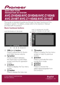
- To avoid shorts in the electrical system, be sure to disconnect the (−) battery cable before beginning installation.
natural_image
Illustration of a hand inserting a battery into a terminal block (no text or symbols)To prevent damage
- When disconnecting a connector, pull the connector itself. Do not pull the lead, as you may pull it out of the connector.
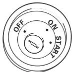
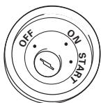
- This unit cannot be installed in a vehicle that does not have an ACC (accessory) position on the ignition switch.
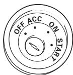
ACC position

No ACC position
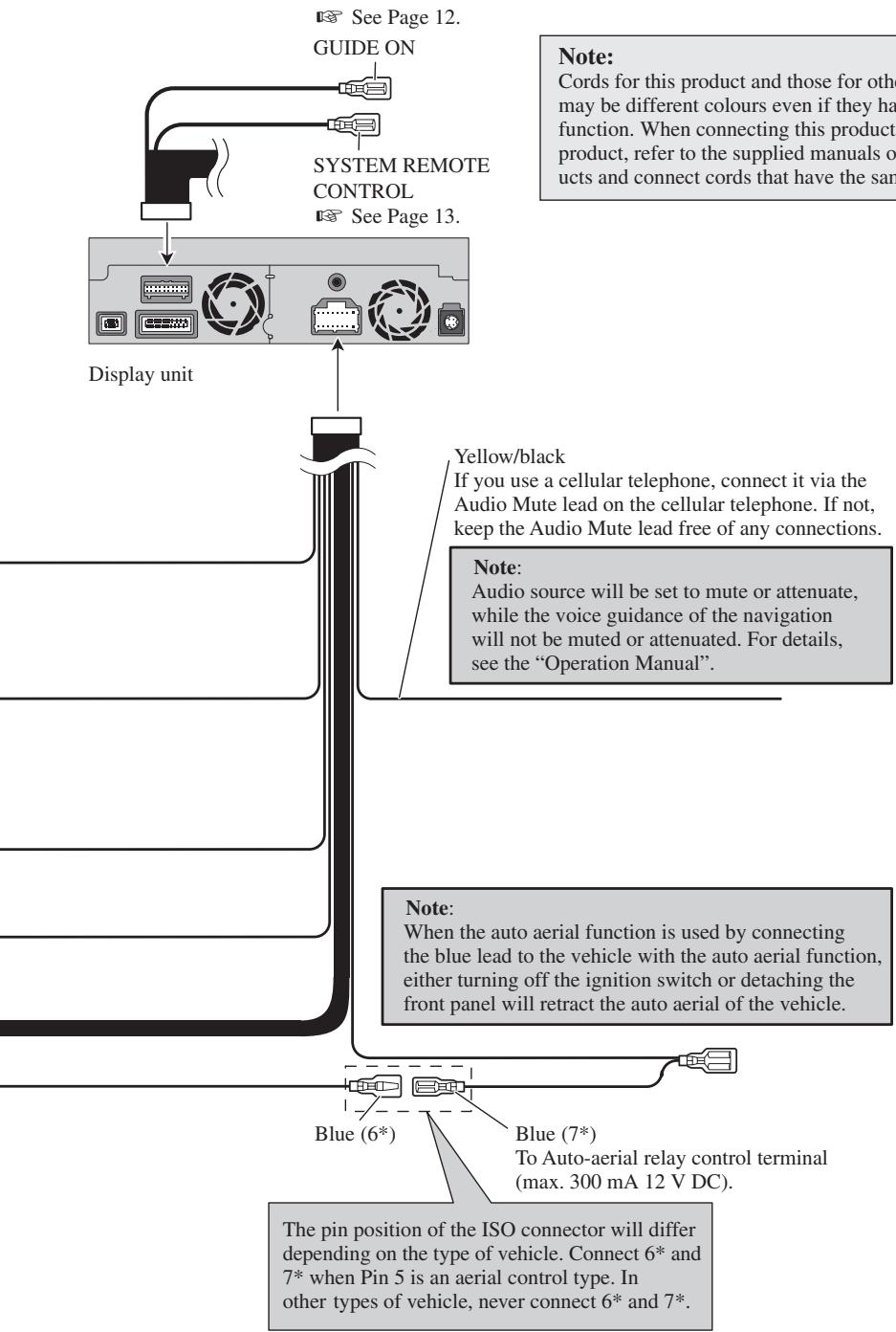
- When the auto aerial function is used by connecting the blue lead to the vehicle with the auto aerial function, either turning off the ignition switch or detaching the front panel will retract the auto aerial of the vehicle.
- To avoid short-circuiting, cover the disconnected lead with insulating tape. It is especially important to insulate all unused speaker leads, which if left uncovered may cause a short circuit.
- Attach the connectors of the same colour to the corresponding coloured port, i.e., blue connector to the blue port, black to black, etc.
- The black lead is earth. Please earth this lead separately from the earth of high-current products such as power amps.
Do not earth more than one product together with the earth from another product. For example, you must separately earth any amplifier unit away from the earth of the Hide-away unit. Connecting earths together can cause a fire and/or damage the products if their earths became detached.
- Refer to the owner's manual for details on connecting the power amp and other units, then make connections accordingly.
- When replacing the fuse, be sure to use only a fuse of the rating prescribed on the fuse holder.
- Since a unique BPTL circuit is employed, do not directly earth the side of the speaker lead or connect the sides of the speaker leads together. Be sure to connect the side of the speaker lead to the side of the speaker lead on the display unit.
-
If the RCA pin jack on the unit will not be used, do not remove the caps attached to the end of the connector.
-
Never connect speakers with an output rating of less than 50 W channel or impedance outside of the 4 ohms to 8 ohms specifications to your Navigation system. Connecting speakers with output and/or impedance values other than those noted here may result in the speakers catching fire, emitting smoke, or becoming damaged.
- When this product's source is switched ON, a control signal is output through the blue/white lead. Connect to an external power amp's system remote control (max. 300 mA 12 V DC). If the vehicle features a glass aerial, connect to the aerial booster power supply terminal.
- When an external power amp is being used with this system, be sure not to connect the blue lead to the amp's power terminal. Likewise, do not connect the blue/white lead to the power terminal of the auto aerial. Such connection could cause excessive current drain and malfunction as well as damage to the auto aerial of the vehicle.
Parts supplied
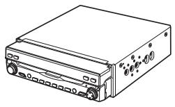
natural_image
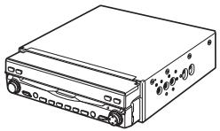
Line drawing of a rectangular electronic device with ports and buttons (no text or symbols)Display unit
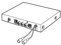
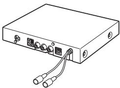
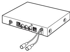
natural_image
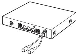
Line drawing of a rectangular electronic device with two ports and two cables (no text or symbols)Hide-away unit

natural_image
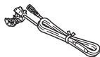
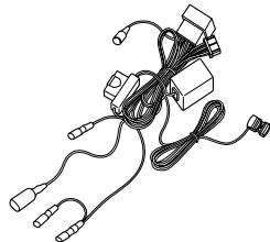
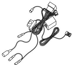
Line drawing of a medical or electronic device with coiled wires and connectors (no text or symbols)Power cord
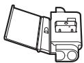
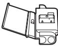
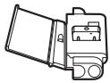
Connector

natural_image
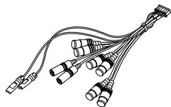
Line drawing of a multi-up cable with connectors (no text or symbols)30-pin cable
Extension lead (for reverse signal)
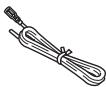
Extension lead (for speed signal)
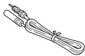
Extension aerial cable
natural_image
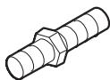
Line drawing of multiple cable connectors with no text or symbolsSystem extension connector
natural_image
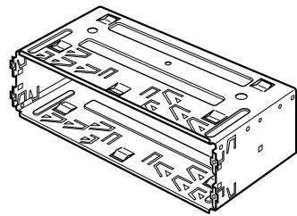
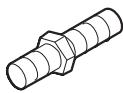
Two identical mechanical rods with textured ends, no text or symbols presentLock tie
Connecting the system
flowchart
graph TD
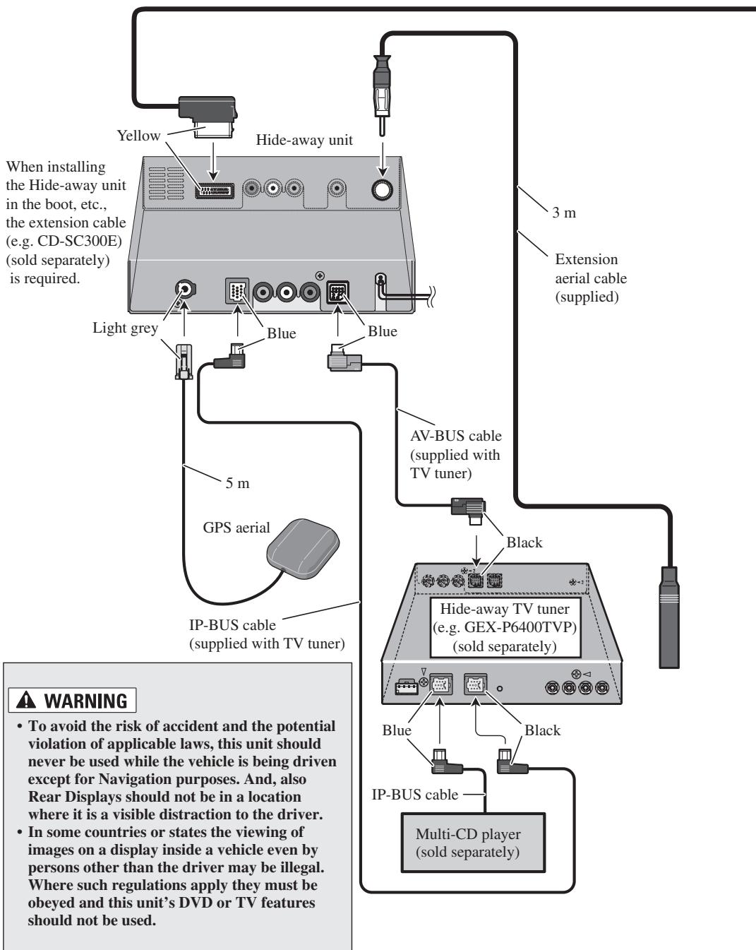
A["When installing the Hide-away unit in the boot, etc., the extension cable (e.g. CD-SC300E) (sold separately) is required."] --> B["White Box"]
B --> C["Light grey"]
B --> D["Blue"]
B --> E["Blue"]
B --> F["Blue"]
B --> G["Blue"]
B --> H["Blue"]
B --> I["Blue"]
B --> J["Blue"]
B --> K["Blue"]
B --> L["Blue"]
B --> M["Blue"]
B --> N["Blue"]
B --> O["Blue"]
B --> P["Blue"]
B --> Q["Blue"]
B --> R["Blue"]
B --> S["Blue"]
B --> T["Blue"]
B --> U["Blue"]
B --> V["Blue"]
B --> W["Blue"]
B --> X["Blue"]
B --> Y["Blue"]
B --> Z["Blue"]
B --> AA["Blue"]
B --> AB["Blue"]
B --> AC["Blue"]
B --> AD["Blue"]
B --> AE["Blue"]
B --> AF["Blue"]
B --> AG["Blue"]
B --> AH["Blue"]
B --> AI["Blue"]
B --> AJ["Blue"]
B --> AK["Blue"]
B --> AL["Blue"]
B --> AM["Blue"]
B --> AN["Blue"]
B --> AO["Blue"]
B --> AP["Blue"]
B --> AQ["Blue"]
B --> AR["Blue"]
B --> AS["Blue"]
B --> AT["Blue"]
B --> AU["Blue"]
B --> AV["Blue"]
B --> AW["Blue"]
B --> AX["Blue"]
B --> AY["Blue"]
B --> AZ["Blue"]
B --> BA["Blue"]
B --> BB["Blue"]
B --> BC["Blue"]
B --> BD["Blue"]
B --> BE["Blue"]
B --> BF["Blue"]
B --> BG["Blue"]
B --> BH["Blue"]
B --> BI["Blue"]
B --> BJ["Blue"]
B --> BK["Blue"]
B --> BL["Blue"]
B --> BM["Blue"]
B --> BN["Blue"]
B --> BO["Blue"]
B --> BP["Blue"]
B --> BQ["Blue"]
B --> BR["Blue"]
B --> BS["Blue"]
B --> BT["Blue"]
B --> BU["Blue"]
B --> BV["Blue"]
B --> BW["Blue"]
B --> BX["Blue"]
B --> BY["Blue"]
B --> Z["Blue"]
B --> AA["Blue"]
B --> AB["Blue"]
B --> AC["Blue"]
B --> AD["Blue"]
B --> AE["Blue"]
B --> AF["Blue"]
B --> AG["Blue"]
B --> AH["Blue"]
B --> AI["Blue"]
B --> AJ["Blue"]
B --> AK["Blue"]
B --> AL["Blue"]
B --> AM["Black"]
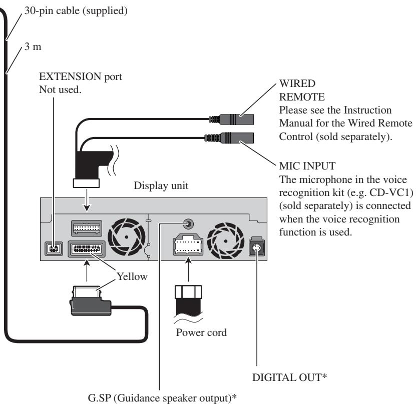
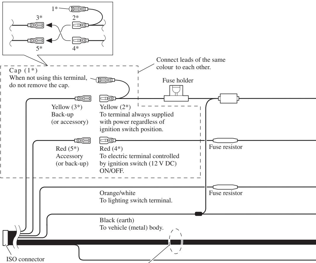
*: This terminal is intended to support future equipment and should not be used if you are using this product by itself.
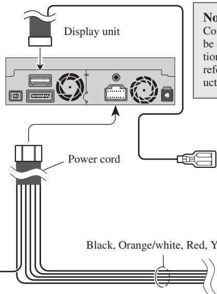
Connecting the power cord (1)
Note:
Depending on the kind of vehicle, the function of 3* and 5* may be different. In this case, be sure to connect 2* to 5* and 4* to 3*.
flowchart
graph TD
    A["Cap (1*)\nWhen not using this terminal,\ndo not remove the cap."] --> B["Yellow (3*)\nBack-up\n(or accessory)"]
    A --> C["Red (5*)\nAccessory\n(or back-up)"]
    A --> D["Orange/white\nTo lighting switch terminal."]
    A --> E["Black (earth)\nTo vehicle (metal) body."]
    A --> F["Fuse holder"]
    A --> G["Fuse resistor"]
    A --> H["ISO connector"]
    style A fill:#f9f,stroke:#333
    style B fill:#ccf,stroke:#333
    style C fill:#ccf,stroke:#333
    style D fill:#ccf,stroke:#333
    style E fill:#ccf,stroke:#333
    style F fill:#ccf,stroke:#333
    style G fill:#ccf,stroke:#333
    style H fill:#ccf,stroke:#333
Note:
In some vehicles, the ISO connector may be divided into two. In this case, be sure to connect to both connectors.
Speaker leads
White: Front left ⊕
White/black: Front left ⊖
Grey: Front right ⊕
Grey/black: Front right ⊖
Green: Rear left ⊕ or Subwoofer ⊕
Green/black: Rear left ⊖ or Subwoofer ⊖
Violet: Rear right ⊕ or Subwoofer ⊕
Violet/black: Rear right ⊖ or Subwoofer ⊖
Connecting the power cord (2)
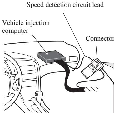
Note: The position of the speed detection circuit depends on the vehicle model. For details, consult your authorised Pioneer dealer or an installation professional. If connection to the speed detection circuit is too difficult, connect the separately sold ND-PG1 speed pulse generator to the pink lead.
Note: The position of the hand-brake switch depends on the vehicle model. For details, consult the vehicle owner's manual or dealer.
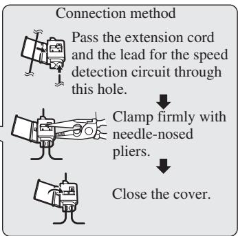
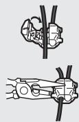
flowchart
graph TD
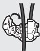
A["Pass the extension cord and the lead for the speed detection circuit through this hole."] --> B["Clamp firmly with needle-nosed pliers."]
B --> C["Close the cover."]

Pink (CAR SPEED SIGNAL INPUT)
The mobile navigation system is connected here to detect the distance the vehicle travels. Always connect the vehicle's speed detection circuit or the ND-PG1 speed pulse generator, sold separately. Failure to make this connection will increase errors in the location display.
WARNING
IMPROPER CONNECTION MAY RESULT IN SERIOUS DAMAGE OR INJURY INCLUDING ELECTRICAL SHOCK, AND INTERFERENCE WITH THE OPERATION OF THE VEHICLE'S ANTILOCK BRAKING SYSTEM, AUTOMATIC GEARBOX AND SPEEDOMETER INDICATION.
Light green
Used to detect the ON/OFF status of the handbrake. This lead must be connected to the power supply side of the handbrake switch. If this connection is made incorrectly or omitted, certain functions of your navigation system will be unusable.
WARNING
LIGHT GREEN LEAD AT POWER CONNECTOR IS DESIGNED TO DETECT PARKED STATUS AND MUST BE CONNECTED TO THE POWER SUPPLY SIDE OF THE HANDBRAKE SWITCH. IMPROPER CONNECTION OR USE OF THIS LEAD MAY VIOLATE APPLICABLE LAW AND MAY RESULT IN SERIOUS INJURY OR DAMAGE.
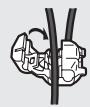
Connection method
natural_image
Technical line drawing of mechanical clamping components (no text or symbols)Clamp the handbrake switch power supply side lead.

Clamp firmly with needle-nosed pliers.

Power supply side
Earth side
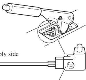
Handbrake switch
Note:
Cords for this product and those for other products may be different colours even if they have the same function. When connecting this product to another product, refer to the supplied Installation manuals of both products and connect cords that have the same function.
Yellow/black (GUIDE ON)
When combining this navigation unit with the other Pioneer audio unit for the vehicle, if the vehicle stereo has yellow/black leads, connect them to those leads. In this way, when the guidance audio is output and when you operate the system by voice, the vehicle stereo is automatically muted to reduce the vehicle stereo volume.
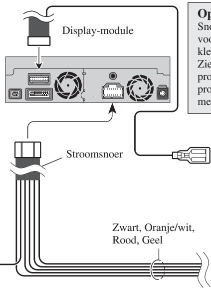
Black, Orange/white, Red, Yellow
See Page 9.
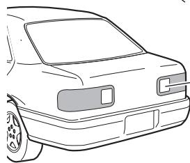
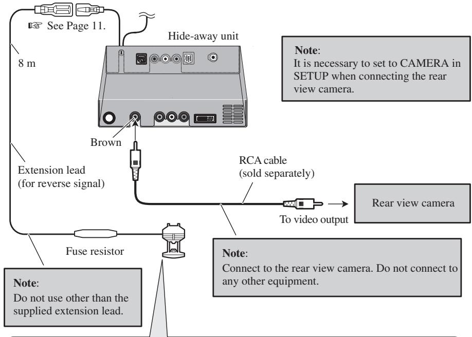
Violet/white (REVERSEGEAR SIGNAL INPUT)
This is connected so that the navigation system can detect whether the vehicle is moving forwards or backwards. Connect the violet/white lead to the lead whose voltage changes when the reverse gear is engaged. Unless connected, the sensor may not detect your vehicle travelling forward/backward properly, and thus the position of your vehicle detected by the sensor may be misaligned from the actual position.
Note: When you use the ND-PG1 speed pulse generator (sold separately), please make sure to connect it.
When you use a rear view camera, please make sure to connect it. Otherwise you cannot switch to rear view camera picture.
Do not use other than the supplied extension lead.
See Page 15.
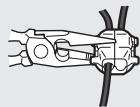
Connection method
Clamp the reversing lamp lead.
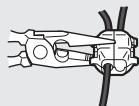

Clamp firmly with needle-nosed pliers.
Fuse resistor
Reversing lamp lead
Extension lead (for reverse signal)
natural_image
Front view line drawing of a car (no text or symbols)Check the position of your vehicle's reversing lamp (the one that lights up - when the gearstick is in reverse [R]) and find the reversing lamp lead in the boot.
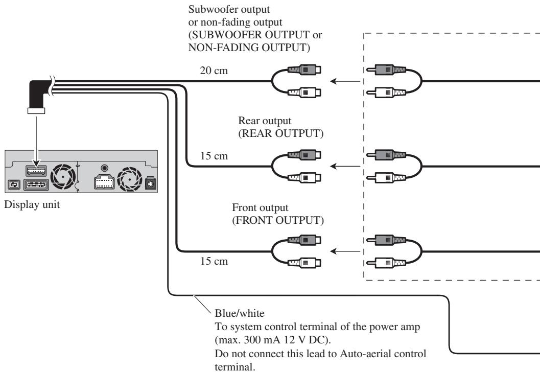
When connecting to separately sold power amp
flowchart
graph TD
    A["Display unit"] --> B["Subwoofer output or non-fading output (SUBWOOFER OUTPUT or NON-FADING OUTPUT)"]
    B --> C["20 cm"]
    B --> D["Rear output (REAR OUTPUT)"]
    B --> E["15 cm"]
    B --> F["Front output (FRONT OUTPUT)"]
    B --> G["15 cm"]
    C --> H["Blue/white To system control terminal of the power amp (max. 300 mA 12 V DC). Do not connect this lead to Auto-aerial control terminal."]
    D --> H
    E --> H
    F --> H
    G --> H
Note:
When a subwoofer is connected to this unit instead of a rear speaker, change the rear output setting in the Initial Setting. (Refer to the Operation Manual.) The subwoofer output of this unit is monaural.
flowchart
graph TD
    A["Input"] --> B["RCA cables (sold separately)"]
    B --> C["Power amp (sold separately)"]
    C --> D["Power amp (sold separately)"]
    D --> E["System remote control"]
    E --> F["Left Front speaker"]
    E --> G["Right Front speaker"]
    E --> H["Left Rear speaker"]
    E --> I["Right Rear speaker"]
    E --> J["Left Subwoofer"]
    J --> K["Subwoofer"]
    style A fill:#f9f,stroke:#333
    style B fill:#ccf,stroke:#333
    style C fill:#cfc,stroke:#333
    style D fill:#fcc,stroke:#333
    style E fill:#cff,stroke:#333
    style F fill:#ffc,stroke:#333
    style G fill:#ffc,stroke:#333
    style H fill:#ffc,stroke:#333
    style I fill:#ffc,stroke:#333
    style J fill:#ffc,stroke:#333
    style K fill:#ffc,stroke:#333
    style_L["Power amp (sold separately)"] --> M["Power amp (sold separately)"]
    M --> N["Power amp (sold separately)"]
    N --> O["Power amp (sold separately)"]
    O --> P["Power amp (sold separately)"]
    P --> Q["Power amp (sold separately)"]
    Q --> R["Power amp (sold separately)"]
    R --> S["Power amp (sold separately)"]
    S --> T["Power amp (sold separately)"]
    T --> U["Power amp (sold separately)"]
    U --> V["Power amp (sold separately)"]
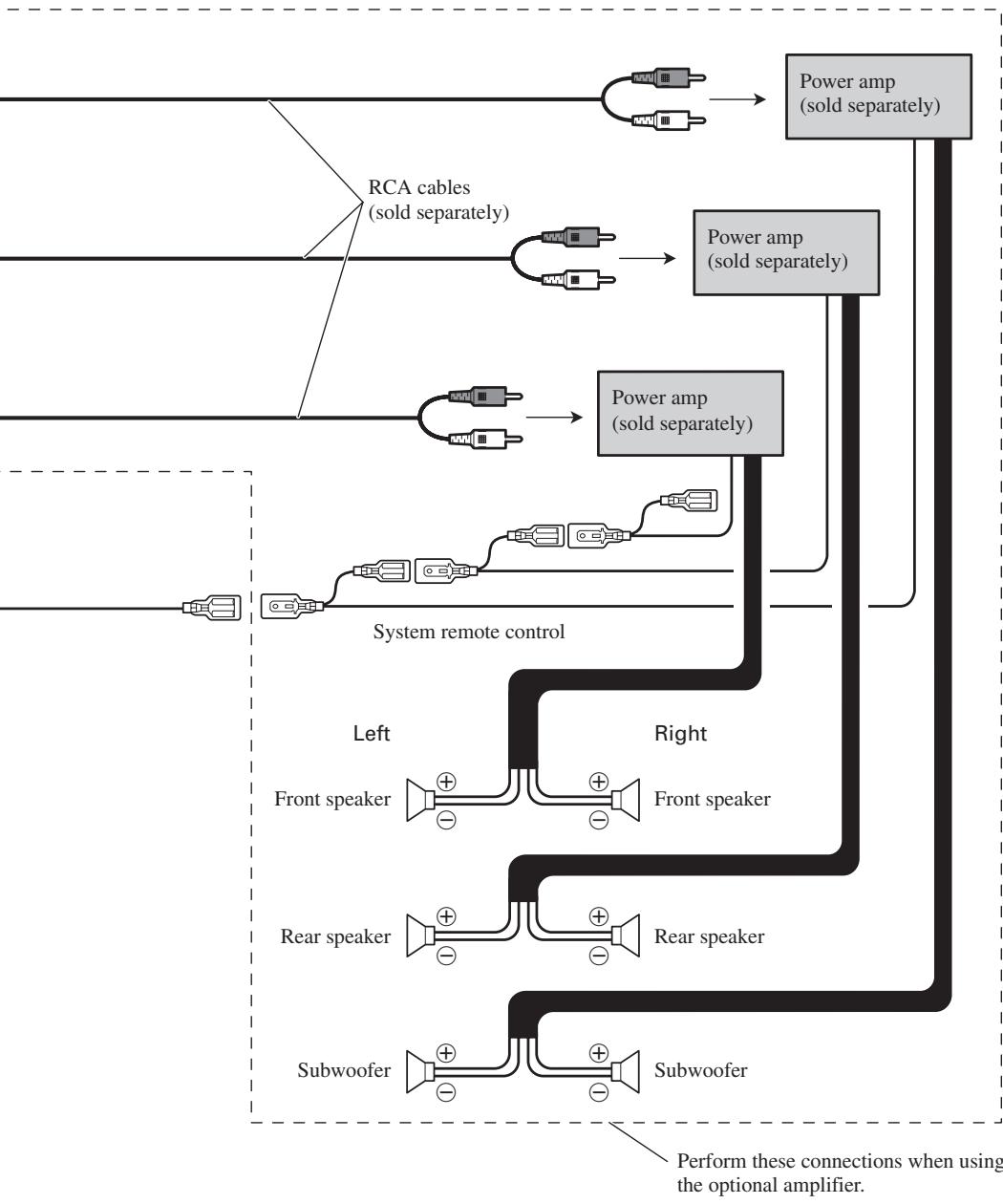
When connecting a Rear view camera
When using this product with a rear view camera, automatic switching to video from a rear view camera is possible when the gear shift is moved to REVERSE (R) position.
Rear view mode also allows you to check what is behind you while driving.
WARNING
USE INPUT ONLY FOR REVERSE OR MIRROR IMAGE REAR VIEW CAMERA. OTHER USE MAY RESULT IN INJURY OR DAMAGE.
CAUTION
- The screen image may appear reversed.
- The rear view camera function is to use this product as an aid to keep an eye on trailers, or backing into a tight parking spot. Do not use this function for entertainment purposes.
- The object in rear view may appear closer or more distant than in reality.
- Please note that the edges of the rear view camera images may differ slightly according to whether full screen images are displayed when backing, and whether the images are used for checking the rear when the vehicle is moving forward.
flowchart
graph TD
A["See Page 11."] --> B["8 m"]
B --> C["Extension lead (for reverse signal)"]
C --> D["Fuse resistor"]
D --> E["Rear view camera"]
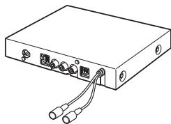
F["Hide-away unit"] --> G["Brown"]
G --> H["RCA cable (sold separately)"]
H --> I["To video output"]
I --> J["Note: Connect to the rear view camera. Do not connect to any other equipment."]
K["Note: Do not use other than the supplied extension lead."] --> L["Note: It is necessary to set to CAMERA in SETUP when connecting the rear view camera."]
Connection method
1. Clamp the lead.

2. Clamp firmly with needle-nosed pliers.
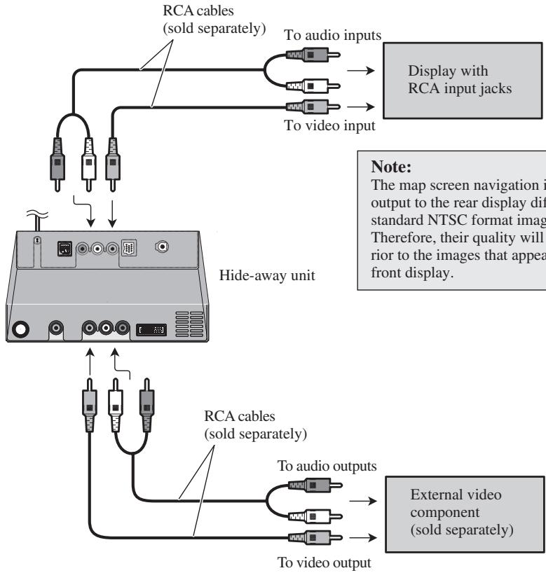
When connecting the external video component and the display
flowchart
graph TD
    A["To audio inputs"] --> B["Display with RCA input jacks"]
    C["To video input"] --> B
    D["RCA cables (sold separately)"] --> E["Hide-away unit"]
    F["To audio outputs"] --> G["External video component (sold separately)"]
    H["To video output"] --> G
    I["Note: The map screen navigation i output to the rear display dif standard NTSC format imag. Therefore, their quality will rior to the images that appea front display."] --> B
    J["Note: The map screen navigation i output to the rear display dif standard NTSC format imag. Therefore, their quality will rior to the images that appea front display."] --> G
- It is necessary to set to AV INPUT or REAR DISP in SET UP when connecting the external video component.
When using a display connected to rear video output
This product's rear video output is for connection of a display to enable passengers in the rear seats to watch the DVD, etc.
WARNING
- NEVER install the rear display in a location that enables the Driver to watch the DVD while Driving.
- NEVER connect rear audio output (REAR OUT) to separately sold power amp.

WARNING
- Pioneer does not recommend that you install or service your Navigation System yourself. Installing or servicing the product may expose you to risk of electric shock or other hazards. Refer all installation and servicing of your navigation unit to authorised Pioneer service personnel.

CAUTION
- Never install the unit in places, or in a manner that where:
* It could injure the driver or passengers if the vehicle stops suddenly.
* It may interfere with the driver's operation of the vehicle, such as on the floor in front of the driver's seat, or close to the steering wheel or gear-stick.
- Make sure there is nothing behind the dashboard or panelling when drilling holes in them. Be careful not to damage fuel lines, brake lines, electronic components, communication wires or power cables.
- When using screws, do not allow them to come into contact with any electrical lead. Vibration may damage wires or insulation, leading to a short circuit or other damage to the vehicle.
- To ensure proper installation, use the supplied parts in the manner specified. If any parts other than the supplied ones are used, they may damage internal parts of the unit or they may work loose and the unit may become detached.
- It is extremely dangerous to allow the GPS aerial lead or microphone lead to become wound around the steering column or gearstick. Be sure to install the unit in such a way that it will not obstruct driving.
- Make sure that leads cannot get caught in a door or the sliding mechanism of a seat, resulting in a short circuit.
- Please confirm the proper function of your vehicle's other equipment following installation of the Navigation System.
- Certain government laws may prohibit or restrict the placement and use of this system in your vehicle. Please comply with all applicable laws and regulations regarding the use, installation and operation of your Navigation System.
- Do not install the display unit or Hide-away unit where it may (i) obstruct the driver's vision, (ii) impair the performance of any of the vehicle's operating systems or safety features, including airbags, hazard lamp buttons or (iii) impair the driver's ability to safely operate the vehicle.
- Install the display unit between the driver's seat and front passenger seat so that it will not be hit by the driver or passenger if the vehicle stops quickly.
- Never install the display unit in front of or next to the place in the dash, door, or pillar from which one of your vehicle's airbags would deploy. Please refer to your vehicle's Owner's Manual for reference to the deployment area of the frontal airbags.
- Do not install the display unit and Hide-away unit in a place where it will impair the performance of any of the vehicle's operating systems, including airbags and headrests.
To guard against electromagnetic interference
- In order to prevent interference, set the following items as far as possible from the display unit and Hide-away unit of this Navigation System, other cables or leads:
- TV aerial and aerial lead
- FM, MW/LW aerial and its lead
- GPS aerial and its lead
In addition you should lay or route each aerial lead as far as possible from other aerial leads.
Do not bind them together, lay or route them together, or cross them.
Such electromagnetic noise will increase the potential for errors in the location display.
Before installing
- Consult with your nearest dealer if installation requires the drilling of holes or other modifications of the vehicle.
- Before finally installing the unit, connect the wiring temporarily, making sure it is all connected up properly, and the unit and the system work properly.
Installing the display unit and Hide-away unit
Installation notes
- Do not install the display unit or Hide-away unit in places where it may become subject to high temperatures or humidity, such as:
* Places close to a heater, vent or air conditioner.
* Places exposed to direct sunlight, such as on top of the dashboard or the rear shelf.
* Places that may be splashed by rain, for example close to the door.
- When installing the unit choose a position that is strong enough to bear the weight of the unit. Choose positions where the display unit or Hide-away unit can be firmly installed, and install it securely.
Unless the display unit or Hide-away unit are securely attached, the current location of the vehicle cannot be displayed correctly.
- Do not install the Hide-away unit on the board covering the spare tyre or other places which are subject to vibration.
- When the Hide-away unit is installed under a front seat, ensure that it does not obstruct the sliding action of the seat.
- When installing the Hide-away unit, choose a position that ensures there will be no contact with luggage. The impact of a heavy weight or sudden shock on the Hide-away unit will adversely affect the accurate display of the current location of the vehicle.
- Avoid installing the Hide-away unit in places where it will interfere with loading and unloading of the spare tyre, jack, tools, etc.
- Check that a disc can be ejected with the display unit installed.
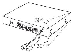
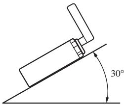
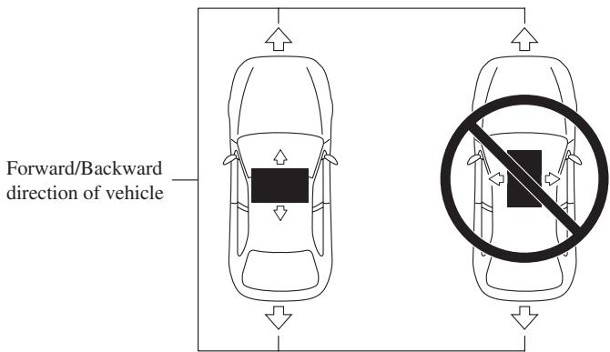
- Install the Hide-away unit horizontally on a surface within +30 degrees to -30 degrees tolerance (within five degrees to the left or right of your vehicle's direction of travel). Mis-installing the unit with the surface tilted more than these tolerances would increase the potential for errors in the location display, and might otherwise cause reduced display performance.
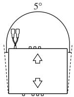
- The cords must not cover up the area shown in the figure below. This is necessary to allow the amplifiers and navigation mechanism to heat dissipate freely.
Display unit
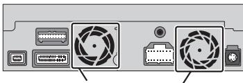
natural_image
Back panel of a computer drive showing fan, ports, and buttons (no text or symbols visible)Do not cover this area.
Hide-away unit
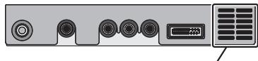
natural_image
Front panel of a computer interface showing ports and a monitor (no text or symbols visible)Do not cover this area.
- The semiconductor laser will be damaged if it overheats, so don't install the unit anywhere hot — for instance, near a heater outlet.
- When installing the Hide-away unit in the boot, use the extension cable (e.g. CD-SC300E) (sold separately).
- Do not install the display unit in a position where the opening of the LCD panel is obstructed by any obstacles, such as the gearstick. This may cause interference with the gearstick, or a malfunction of the mechanism of the display unit.
Parts supplied
natural_image
Line drawing of a rectangular electronic device with ports and buttons (no text or symbols)Display unit

Screw

natural_image
Technical line drawing of a rectangular electronic component with internal slots and mounting holes (no text or symbols)Holder

Side bracket (2 pcs.)

Rubber bush

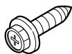
Binding screw
(5 × 6 mm)
(4 pcs.)

Flush surface screw
(5 × 6 mm)
(4 pcs.)
natural_image
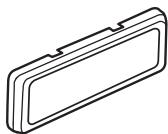
Isometric line drawing of a rectangular object with a recessed top and side gap (no text or symbols)Frame

Screw
(4 × 3 mm)
(4 pcs.)

Fixing screw (2 pcs.)
natural_image
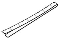
Simple line drawing of a ruler with measurement markings (no text or numbers)Conceal tape

natural_image
Line drawing of a rectangular electronic device with ports and cables (no text or symbols)Hide-away unit

natural_image
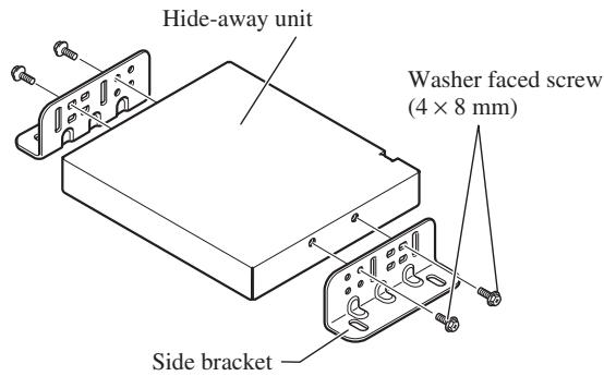
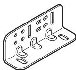
Isometric line drawing of a rectangular electronic device with multiple ports and mounting holes (no text or symbols)Side bracket (2 pcs.)

Washer faced screw
(4 × 8 mm)
(4 pcs.)
Self-tapping screw
(6 × 16 mm)
(4 pcs.)
CAUTION
- Install with the left and right sides of the Hide-away unit perpendicular or parallel to your vehicle's direction of travel. Do not install diagonally to your vehicle's direction of travel or the current location will be displayed incorrectly.
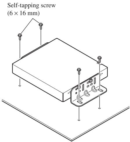
Installing the Hide-away unit
1. Attach the side brackets to the Hide-away unit.
When the Hide-away unit is installed on the floor or the installation board under the passenger seat, etc., the side brackets should be attached to the unit.
Use the following holes in the side brackets.
If the positions of the side plates are shifted in parallel you can also use other holes that match up with the holes in the Hide-away unit.
When the Hide-away unit is installed under the passenger seat, etc., use the installation board.
2. Decide on the installation position, and drill the holes.

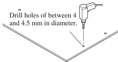
3. Secure it firmly using the self-tapping screws.
DIN Front/Rear-mount
This unit can be properly installed either from “Front” (conventional DIN Front-mount) or “Rear” (DIN Rear-mount installation, using threaded screw holes at the sides of unit chassis). For details, refer to the following illustrated installation methods.
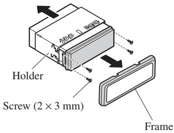
Before installing the unit
- Remove the frame and the holder.
Pull out to remove the frame and then loosen the screws (2 × 3 mm) to remove the holder. (When reattaching the frame, point the side with a groove downwards and attach it.)
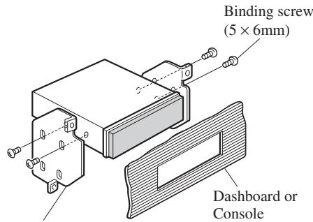
DIN Front-mount
Installation with the rubber bush
1. Decide the position of the side brackets.
When installing in a shallow space, change the position of side brackets. In this case, stick conceal tape on parts that protrude from the dashboard.
2. Install the unit into the dashboard.
After inserting the holder into the dashboard, select the appropriate tabs according to the thickness of the dashboard material and bend them.
(Install as firmly as possible using the top and bottom tabs. To secure, bend the tabs 90 degrees.)
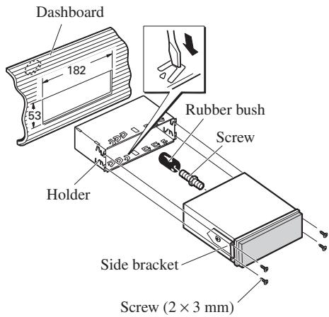
• After installing the unit into the dashboard, reattach the frame.
- If you prefer an off-set installation in which the front panel is pushed further back, when there is a space available at the back of the unit, use AD-GA10 (sold separately).
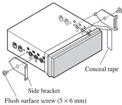
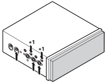
DIN Rear-mount
Installation using the screw holes on the side of the unit
- Fastening the unit to the factory radio-mounting bracket.
Select a position where the screw holes of the bracket and the screw holes of this product become aligned (are fitted), and tighten the screws at 2 places on each side. Use any of screws (4 × 3 mm), binding screws (5 × 6 mm) or flush surface screws (5 × 6 mm), depending on the shape of the screw holes in the bracket.
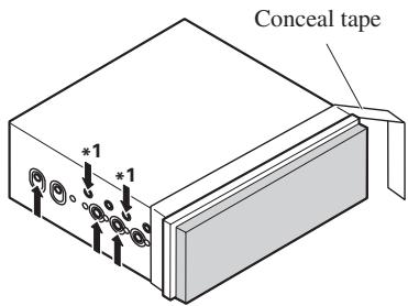
*1 Use screws (4 × 3 mm) only.
natural_image
Isometric view of a rectangular electronic device with labeled ports and connectors (no text or symbols beyond basic labels)- When installing in a shallow space, use the following screw holes. In this case, stick conceal tape on parts that protrude from the dashboard.
Factory radio mounting bracket
Fixing the front panel
If you do not operate the removing and attaching the front panel function, use the supplied fixing screws to fix the front panel to this unit.
- Fix the front panel to the unit using fixing screws after removing the front panel.
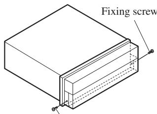
Fixing screw
CAUTION
- Do not cut the GPS aerial lead to shorten it or use an extension to make it longer. Altering the aerial cable could result in a short circuit or malfunction and permanent damage to the product.
Installation notes
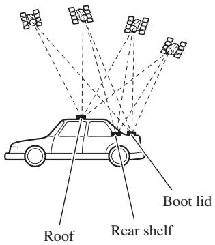
- The aerial should be installed on a level surface where radio waves will be blocked as little as possible. Radio waves cannot be received by the aerial if reception from the satellite is blocked.
Installation on the vehicle roof or boot lid is recommended to optimise reception.
- When installing the GPS aerial inside the vehicle, be sure to use the metal sheet provided with your system. If this is not used, the reception sensitivity will be poor.
- Do not cut the accessory metal sheet. This would reduce the sensitivity of the GPS aerial.
- Take care not to pull the aerial lead when removing the GPS aerial. The magnet attached to the aerial is very powerful, and the lead may become detached.
- The GPS aerial is installed with a magnet. When installing the GPS aerial, be careful not to scratch the vehicle body.
- When installing the GPS aerial on the outside of the vehicle, always put it in the vehicle when going through an automatic vehicle wash. If it is left on the outside it may be knocked off and scratch the vehicle body.
- Do not paint the GPS aerial, as this may affect its performance.
Parts supplied
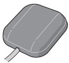
GPS aerial

Metal sheet

Clamp (5 pcs.)

Waterproof pad
When installing the aerial inside the vehicle (on the rear shelf)
Affix the metal sheet on as level a surface as possible where the GPS aerial faces the window. Place the GPS aerial on the metal sheet. (The GPS aerial is fastened with its magnet.)
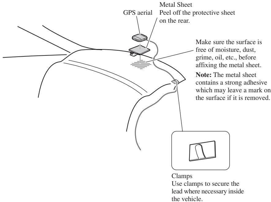
Note:
- When attaching the metal sheet, do not cut it into small pieces.
- Some models use window glass that does not allow signals from GPS satellites to pass through. On such models, install the GPS aerial on the outside of the vehicle.
When installing the aerial outside the vehicle (on the body)
Put the GPS aerial in a position as level as possible, such as on the roof or boot lid. (The GPS aerial is fastened with a magnet.)
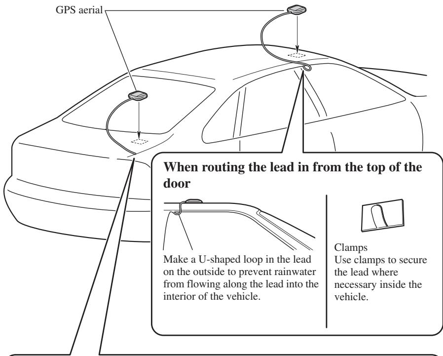
When routing the lead in from inside the boot
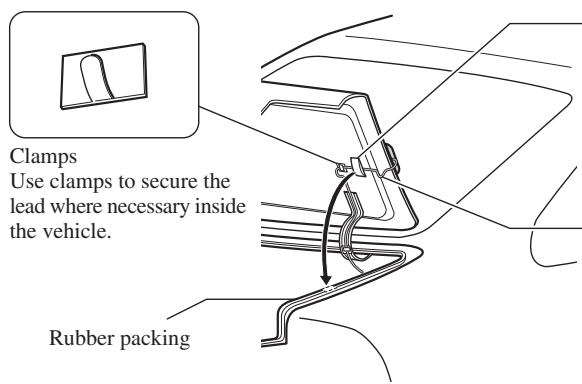
Waterproof pad Make sure the waterproof pad contacts the top of the rubber packing.
Make a U-shaped loop in the lead outside the rubber packing to prevent rainwater from flowing along the lead into the interior of the vehicle.
1. Reconnecting the battery.
First, double-check that all connections are correct and that the unit is installed correctly. Reassemble all vehicle components that you previously removed. Then reconnect the negative (−) cable to the negative (−) terminal of the battery.
2. Start the engine.
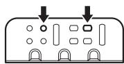
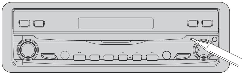
3. Press the RESET button on the display unit.
Press the RESET button on the display unit using a pointed object such as the tip of a pen.
natural_image
Line drawing of a device rear panel with buttons and a pen inserted (no text or symbols)4. Enter the following settings:
• Install the program in the navigation system.
- Drive until the initialised sensors start operating normally.
- Set the time and language.
Set the navigation system as explained in the “Operation Manual” or “Hardware Manual”.
Note:
If you reconnected the Hide-away unit, press the RESET button.
After installing the unit, be sure to check at a safe place that the vehicle is performing normally.
natural_image
Illustration of a hand using a tool to adjust or install an electrical component (no text or symbols visible)Para impedir daños
Posición ACC
Sin posición ACC
natural_image
Line drawing of a rectangular electronic device with ports and buttons (no text or symbols)Unidad de pantalla
natural_image
Line drawing of a rectangular electronic device with two cables and ports (no text or symbols)natural_image
Line drawing of a wireless cable and connector with connectors (no text or symbols)natural_image
Line drawing of a multi-up cable with connectors (no text or symbols)natural_image
Line drawing of multiple cable connectors with no text or symbolsnatural_image
Two identical cylindrical metal rods with textured ends, no text or symbols presentnatural_image
Technical line drawing of two mechanical clamping or fastening mechanisms (no text or symbols)natural_image
Technical line drawing of a mechanical clamp or lever assembly with a magnified inset showing internal components (no text or symbols)natural_image
Line drawing of a car front view showing grille and side panels (no text or symbols)natural_image
Back panel of a computer mouse showing two camera blades with buttons and ports (no text or symbols visible)No cubra esta zona.
natural_image
Front panel of a computer interface showing ports, buttons, and a display unit (no text or symbols visible)No cubra esta zona.
natural_image
Line drawing of a rectangular electronic device with ports and buttons (no text or symbols)Unidad de pantalla

Tornillo

natural_image
Technical line drawing of a rectangular electronic component with internal slots and mounting holes (no text or symbols)Soporte
natural_image
Isometric line drawing of a rectangular object with a recessed top and side gap (no text or symbols)Marco
natural_image
Simple line drawing of a ruler with measurement markings (no text or numbers)Cinta oculta

natural_image
Line drawing of a rectangular electronic device with ports and cables (no text or symbols)natural_image
Isometric line drawing of a rectangular electronic component with multiple slots and mounting holes (no text or symbols)natural_image
Isometric view of a rectangular electronic device with labeled ports and connectors (no text or symbols beyond basic labels)natural_image
Line drawing of a CD-ROM rear panel with buttons and a stylus inserted (no text or symbols)natural_image
Illustration of a hand using a tool to adjust or install an electric battery (no text or symbols visible)ACC-Stellung

Keine ACC-Stellung
natural_image
Line drawing of a rectangular electronic device with ports and buttons (no text or symbols)Display-Einheit
natural_image
Line drawing of a rectangular electronic device with two ports and wiring (no text or symbols)Hideaway-Einheit

natural_image
Line drawing of a multi-pin electronic device with cables and connectors (no text or symbols)Betriebsstromkabel
Anschluss

natural_image
Coiled cable with connectors, no text or symbols visible30-poliges Kabel
natural_image
Line drawing of multiple coaxial connectors with wires, no text or symbols presentnatural_image
Two identical isometric metal rods with textured ends, no text or symbols presentKabelbinder
Gelb/schwarz (GUIDE ON)
natural_image
Front view line drawing of a car (no text or symbols)natural_image
Line drawing of a rectangular electronic device with ports and buttons (no text or symbols)Display-Einheit
Schraube
natural_image
Technical line drawing of a rectangular electronic component with internal slots and mounting holes (no text or symbols)Halterung
natural_image
Isometric line drawing of a rectangular object with a recessed top and side gap (no text or symbols)Rahmen
natural_image
Simple line drawing of a ruler with measurement markings (no text or numbers)Abdeckband

natural_image
Line drawing of a rectangular electronic device with ports and cables (no text or symbols)Hideaway-Einheit

natural_image
Isometric line drawing of a rectangular electronic component with multiple curved slots and mounting holes (no text or symbols)natural_image
Isometric diagram of a rectangular block with internal components and mounting holes, no text or symbols presentnatural_image
Line drawing of a CD-ROM rear panel with buttons and a stylus inserted (no text or symbols)natural_image
Illustration of a hand using a tool to adjust or install an electrical component (no text or symbols visible)Position ACC
Pas de position ACC
natural_image
Line drawing of a rectangular electronic device with ports and buttons (no text or symbols)Unité d'affichage

natural_image
Line drawing of a rectangular electronic device with ports and cables (no text or symbols)Unité déportée
natural_image
Line drawing of a multi-pin electronic device with cables and connectors (no text or symbols)natural_image
Illustration of a coiled cable with connectors (no text or symbols)Câble 30 broches
natural_image
Line drawing of two cables tied with a strap (no text or symbols)natural_image
Line drawing of multiple cable connectors with connectors and wires (no text or symbols)natural_image
Two identical mechanical rods with textured ends, no text or symbols presentAttache
natural_image
Front view line drawing of a car (no text or symbols)Cordon-rallonge
natural_image
Back panel of a computer drive showing two fan modules with buttons and ports (no text or symbols visible)natural_image
Front panel of a computer drive showing ports and a display unit (no text or symbols visible)natural_image
Line drawing of a rectangular electronic device with ports and buttons (no text or symbols)Unité d'affichage

Vis

natural_image
Technical line drawing of a rectangular electronic component with internal slots and mounting holes (no text or symbols)Support
natural_image
Isometric line drawing of a rectangular object with a recessed top and side gap (no text or symbols)Cadre
natural_image
Simple line drawing of a ruler with measurement markings (no text or numbers)natural_image
Line drawing of a rectangular electronic device with ports and cables (no text or symbols)Unité déportée
natural_image
Isometric line drawing of a rectangular device with multiple circular cutouts and mounting holes (no text or symbols)natural_image
Isometric view of a rectangular electronic component with mounting holes and a base, showing no text or symbols.natural_image
Line drawing of a CD-ROM rear panel with buttons and a stylus inserted (no text or symbols)natural_image
Illustration of a hand using a tool to adjust or install an electric battery (no text or symbols visible)Per evitare danni
Posizione ACC

natural_image
Line drawing of a rectangular electronic device with ports and buttons (no text or symbols)Unità display

natural_image
Line drawing of a rectangular electronic device with two ports and cables (no text or symbols)Unità a scomparsa
natural_image
Line drawing of a medical or electronic device with coiled wires and connectors (no text or symbols)natural_image
Line drawing of a coiled cable with connectors (no text or symbols)Cavo da 30 contatti
natural_image
Line drawing of a coiled cable with two connectors (no text or symbols)natural_image
Line drawing of multiple cable connectors with no text or symbolsnatural_image
Two identical isometric metal tools with grooves and end caps (no text or symbols)natural_image
Front view line drawing of a car (no text or symbols)natural_image
Back panel of a computer drive showing two fan modules with buttons and ports (no text or symbols visible)natural_image
Front panel of a computer drive showing ports, buttons, and a display (no text or symbols visible)natural_image
Line drawing of a rectangular electronic device with ports and buttons (no text or symbols)Unità display
Vite

natural_image
Technical line drawing of a rectangular electronic component with internal slots and mounting holes (no text or symbols)Supporto

Staffa laterale
(2 pz.)

Boccola in gomma
natural_image
Isometric line drawing of a rectangular object with a recessed top and side gap (no text or symbols)Cornice

Vite
(4 × 3 mm)
(4 pz.)
natural_image
Simple line drawing of a ruler with measurement markings (no text or numbers)Nastro di copertura
natural_image
Line drawing of a rectangular electronic device with ports and cables (no text or symbols)Unità a scomparsa

natural_image
Isometric line drawing of a rectangular electronic component with multiple slots and mounting holes (no text or symbols)Staffa laterale (2 pz.)
natural_image
Isometric view of a rectangular electronic device with multiple ports and mounting holes (no text or symbols)natural_image
Line drawing of a device rear panel with buttons and a hand holding a screwdriver (no text or symbols)natural_image
Illustration of a hand using a tool to adjust or install an electric battery (no text or symbols visible)ACC stand

Geen ACC stand
natural_image
Line drawing of a rectangular electronic device with ports and buttons (no text or symbols)Display-module
natural_image
Line drawing of a rectangular electronic device with two leads and a terminal block (no text or symbols)Verborgen eenheid

natural_image
Line drawing of a medical or electronic device with cables, connectors, and a central connector (no text or symbols)Stroomsnoer
Stekker
natural_image
Illustration of a coiled cable with connectors (no text or symbols)30-pins kabel
natural_image
Line drawing of multiple cable connectors with no text or symbolsnatural_image
Two identical mechanical link components with textured ends and mounting holes (no text or symbols)Vergrendeling
natural_image
Front view of a portable electronic device with ports and buttons (no visible text or symbols)Verborgen eenheid
natural_image
Technical line drawing of a mechanical clamp or bracket assembly with a magnified inset showing internal components (no text or symbols)Handremschakelaar
Opmerking:
natural_image
Front view line drawing of a car (no text or symbols)natural_image
Back panel of a computer drive showing two fan modules with buttons and ports (no text or symbols visible)natural_image
Front panel of a computer drive showing ports and a display unit (no text or symbols visible)natural_image
Line drawing of a rectangular electronic device with ports and buttons (no text or symbols)Display-module

Schroef

natural_image
Technical line drawing of a rectangular electronic component with internal slots and mounting holes (no text or symbols)Houder

Zijbeugel
(2 st.)

Rubbermof
natural_image
Isometric line drawing of a rectangular object with a recessed top and side gap (no text or symbols)Frame

Schroef
(4 × 3 mm)
(4 st.)
natural_image
Simple line drawing of a ruler with measurement markings (no text or numbers)Camouflageband

natural_image
Line drawing of a rectangular electronic device with ports and cables (no text or symbols)Verborgen eenheid

natural_image
Isometric line drawing of a rectangular electronic component with multiple slots and mounting holes (no text or symbols)Zijbeugel (2 st.)
natural_image
Isometric view of a rectangular electronic device with mounting holes and a base plate (no text or symbols)natural_image
Line drawing of a CD-ROM rear panel with buttons and a stylus inserted (no text or symbols)PIONEER ELECTRONICS (USA) INC.
P.O. Box 1540, Long Beach, California 90801-1540, U.S.A.
TEL: (800) 421-1404
PIONEER EUROPE NV
Haven 1087, Keetberglaan 1, B-9120 Melsele, Belgium
TEL: (0) 3/570.05.11
PIONEER ELECTRONICS ASIACENTRE PTE. LTD.
253 Alexandra Road, #04-01, Singapore 159936
TEL: 65-6472-1111
PIONEER ELECTRONICS AUSTRALIA PTY. LTD.
178-184 Boundary Road, Braeside, Victoria 3195, Australia
TEL: (03) 9586-6300
PIONEER ELECTRONICS OF CANADA, INC.
300 Allstate Parkway, Markham, Ontario L3R OP2, Canada
TEL: (905) 479-4411
PIONEER ELECTRONICS DE MEXICO, S.A. de C.V.
Blvd. Manuel Avila Camacho 138 10 piso
Col.Lomas de Chapultepec, Mexico, D.F. 11000
TEL: 55-9178-4270
先鋒股份有限公司
Published by Pioneer Corporation.
Copyright © 2004 by Pioneer Corporation.
All rights reserved.
Publication de Pioneer Corporation.
Copyright © 2004 Pioneer Corporation.