
UH650DZ - Tondeuse à fil MAKITA - Free user manual and instructions
Find the device manual for free UH650DZ MAKITA in PDF.

| Product Type | Cordless Hedge Trimmer |
| Brand | Makita |
| Model | UH650DZ |
| Blade Length | 650 mm |
| Strokes per Minute | 1,000 - 1,800 min⁻¹ (adjustable via 6-speed dial) |
| Overall Length | 1,154 mm |
| Net Weight | 5.2 kg (without battery cartridge) |
| Rated Voltage | DC 36 V |
| Power Source | Makita 36 V Li-ion battery cartridge (not included) |
| Noise Level | Sound pressure 84.3 dB(A), sound power 92.3 dB(A), K=2.5 dB(A) |
| Vibration Level | 3.0 m/s² (hedge trimming), K=1.5 m/s² |
| Adjustable Handle | Rotates 90° left/right, locks at 45° and 90° positions |
| Safety Features | Dual switch system (triggers A+B), blade cover, battery protection system |
| Cutting Capacity | Max branch diameter 10 mm |
| Accessories Included | Blade cover, chip receiver (optional), arm cord hook (optional) |
| Maintenance | Lubricate blades before and during use; replace carbon brushes when worn |
| Battery Compatibility | Makita 36 V batteries (e.g., BL3622A with capacity indicator) |
| EC Declaration | Conforms to 2000/14/EC and 2006/42/EC, CE marked |
Frequently Asked Questions - UH650DZ MAKITA
User questions about UH650DZ MAKITA
0 question about this device. Answer the ones you know or ask your own.
Ask a new question about this device
Download the instructions for your Tondeuse à fil in PDF format for free! Find your manual UH650DZ - MAKITA and take your electronic device back in hand. On this page are published all the documents necessary for the use of your device. UH650DZ by MAKITA.
USER MANUAL UH650DZ MAKITA
natural_image
Line drawing of a manual chain-linking tool (no text or symbols)
1
2
natural_image
Technical line drawing of a mechanical component with no visible text or symbols3
011233
4
natural_image
Line drawing of a hand using a tool to spread soil or vegetation, with no text or symbols present.5
natural_image
Illustration of a hand using a tool to cut a block of material, with no visible text or symbols.6
011151
7
natural_image
Illustration of hands using a tool to cut a textured surface with a ruler and bracket (no text or symbols)8
natural_image
Line drawing of a person using a tool to cut or spread debris (no text or symbols)9
011154
natural_image
Diagram of a mechanical device with an arrow indicating motion, surrounded by textured background (no text or symbols)1 0
natural_image
Illustration of a robotic arm holding a tool, with an arrow indicating motion (no text or symbols present)1 1
1 2
009290
2 2
natural_image
Diagram of a mechanical tool with a spring and pin, showing motion direction (no text or symbols)2 3
009302
2 4
natural_image
Mechanical assembly diagram showing a hand operating a screwdriver with a separate inset view of a pin inserted into a housing (no text or symbols present)2 5
011261
natural_image
Pure mechanical diagram showing a spring-loaded component with no text or symbols2 6
001145
2 7
011161
2 8
011162
natural_image
Diagram showing a tool with a curved arrow indicating rotation or movement, next to a vertical line (no text or symbols present)2 9
011160
ENGLISH (Original instructions)
| Explanation of general view | ||
| 1-1. Red indicator | 12-3. Nut | 19-1. Crank |
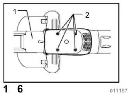
| 1-2. Button | 12-4. Shear blade | 20-1. Screws |
| 1-3. Battery cartridge | 13-1. Nut | 20-2. Shear blade |
| 2-1. Switch trigger B | 13-2. Branch catcher | 21-1. Crank |
| 2-2. Switch trigger A | 14-1. Hooks | 22-1. Oval hole of shear blade |
| 3-1. Adjusting dial | 14-2. Fit the hooks into groove | 24-1. Oval hole of shear blade |
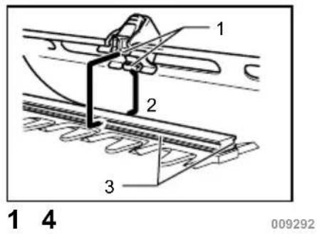
| 4-1. Hook | 14-3. Grooves | 24-2. Crank |
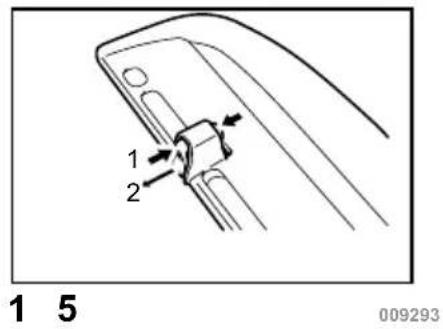
| 4-2. Belt | 15-1. Press the levers on both sides | 25-1. Crank |
| 7-1. Trimming direction | 15-2. Unlock the hooks | 26-1. Limit mark |
| 7-2. Hedge surface to be trimmed | 16-1. Blade cover | 27-1. Holder cap cover |
| 7-3. Tilt the blades. | 16-2. Screws | 27-2. Screwdriver |
| 8-1. String | 17-1. Under cover | 28-1. Brush holder cap |
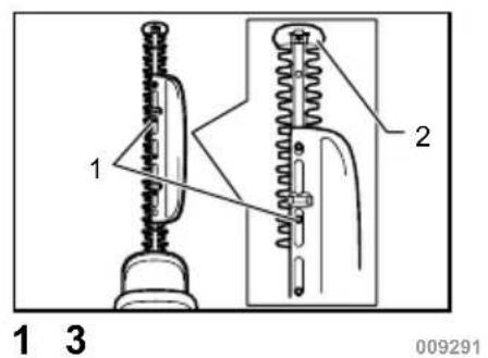
| 12-1. Press | 17-2. Blade cover | 28-2. Screwdriver |
| 12-2. Chip receiver | 18-1. Plate | |
SPECIFICATIONS
| Model | BUH550 | UH550D | BUH650 | UH650D |
| Blade length 550 mm 650 mm | ||||
| Strokes per minute (min ^-1 ) 1,000 - 1,800 | 1,000 - 1,800 | |||
| Overall length 1,070 mm 1,074 mm | 1,150 mm 1,154 mm | |||
| Net weight 5.1 kg 5.2 kg | ||||
| Rated voltage D.C.36 V D.C.36 V | ||||
- Due to our continuing program of research and development, the specifications herein are subject to change without notice.
- Specifications and battery cartridge may differ from country to country.
- Weight, with battery cartridge, according to EPTA-Procedure 01/2003
END013-3
ENG905-1
Symbol
The following show the symbols used for the equipment. Be sure that you understand their meaning before use.


Cd Ni-MH Li-ion
Read instruction manual.
Do not expose to rain.
Only for EU countries
Do not dispose of electric equipment or battery pack together with household waste material!
In observance of European Directive 2012/19/EU on waste electric and electronic equipment, 2006/66/EC on batteries and accumulators and waste batteries and accumulators and their implementation in accordance with national laws, electric equipment and battery pack that have reached the end of their life must be collected separately and returned to an environmentally compatible recycling facility.
ENE014-1
Intended use
The tool is intended for trimming hedges.
Noise
The typical A-weighted noise level determined according to EN60745:
Model BUH550, UH550D
Sound pressure level ( L_pA ): 85.1 dB(A)
Sound power level ( L_WA ): 93.1 dB(A)
Uncertainty (K) : 2.5 dB(A)
Model BUH650, UH650D
Sound pressure level ( L_pA ): 84.3 dB(A)
Sound power level ( L_WA ): 92.3 dB(A)
Uncertainty (K): 2.5 dB(A)
Wear ear protection
ENG900-1
Vibration
The vibration total value (tri-axial vector sum) determined according to EN60745:
Model BUH550,UH550D
Work mode : hedge trimming
Vibration emission ( a_h ): 2.5 m/s ^2
Uncertainty (K) : 1.5 m/s ^2
Model BUH650,UH650D
Work mode : hedge trimming
Vibration emission ( a_h ): 3.0 m/s ^2
Uncertainty (K) : 1.5 m/s ^4
ENG901-1
- The declared vibration emission value has been measured in accordance with the standard test method and may be used for comparing one tool with another.
- The declared vibration emission value may also be used in a preliminary assessment of exposure.
WARNING:
- The vibration emission during actual use of the power tool can differ from the declared emission value depending on the ways in which the tool is used.
- Be sure to identify safety measures to protect the operator that are based on an estimation of exposure in the actual conditions of use (taking account of all parts of the operating cycle such as the times when the tool is switched off and when it is running idle in addition to the trigger time).
ENH032-3
For European countries only
EC Declaration of Conformity
We Makita Corporation as the responsible manufacturer declare that the following Makita machine(s):
Designation of Machine:
Cordless Hedge Trimmer
Model No./ Type: BUH550, UH550D, BUH650,
UH650D
Specifications: see "SPECIFICATIONS" table.
are of series production and
Conforms to the following European Directives:
2000/14/EC, 2006/42/EC
And are manufactured in accordance with the following standards or standardised documents: EN60745
The technical documentation is kept by:
Makita International Europe Ltd.
Technical Department,
Michigan Drive, Tongwell,
Milton Keynes, Bucks MK15 8JD, England
The conformity assessment procedure required by Directive 2000/14/EC was in Accordance with annex V. Model BUH550, UH550D
Measured Sound Power Level: 93.1dB (A)
Guaranteed Sound Power Level: 94dB (A)
Model BUH650, UH650D
Measured Sound Power Level: 92.4dB (A)
Guaranteed Sound Power Level: 94dB (A)
30.11.2009

Tomoyasu Kato
Director
Makita Corporation
3-11-8, Sumiyoshi-cho,
Anjo, Aichi, 446-8502, JAPAN
GEA010-1
General Power Tool Safety Warnings
⚠ WARNING Read all safety warnings and all instructions. Failure to follow the warnings and instructions may result in electric shock, fire and/or serious injury.
Save all warnings and instructions for future reference.
GEB062-5
CORDLESS HEDGE TRIMMER SAFETY WARNINGS
- Keep all parts of the body away from the cutter blade. Do not remove cut material or hold material to be cut when blades are moving. Make sure the switch is off when clearing jammed material. A moment of inattention while operating the hedge trimmer may result in serious personal injury.
- Carry the hedge trimmer by the handle with the cutter blade stopped. When transporting or storing the hedge trimmer always fit the cutting device cover. Proper handling of the hedge trimmer will reduce possible personal injury from the cutter blades.
- Hold the power tool by insulated gripping surfaces only, because the cutter blade may contact hidden wiring. Cutter blades contacting a "live" wire may make exposed metal parts of the power tool "live" and could give the operator an electric shock.
- Do not use the hedge trimmer in the rain or in wet or very damp conditions. The electric motor is not waterproof.
- First-time users should have an experienced hedge trimmer user show them how to use the trimmer.
- The hedge trimmer must not be used by children or young persons under 18 years of age. Young persons over 16 years of age may be exempted from this restriction if they are undergoing training under the supervision of an expert.
- Use the hedge trimmer only if you are in good physical condition. If you are tired, your attention
will be reduced. Be especially careful at the end of a working day. Perform all work calmly and carefully. The user is responsible for all damages to third parties.
- Never use the trimmer when under the influence of alcohol, drugs or medication.
- Work gloves of stout leather are part of the basic equipment of the hedge trimmer and must always be worn when working with it. Also wear sturdy shoes with anti-skid soles.
- Before starting work check to make sure that the trimmer is in good and safe working order. Ensure guards are fitted properly. The hedge trimmer must not be used unless fully assembled.
- Make sure you have a secure footing before starting operation.
- Hold the tool firmly when using the tool.
- Do not operate the tool at no-load unnecessarily.
- Immediately switch off the motor and remove the battery cartridge if the cutter should come into contact with a fence or other hard object. Check the cutter for damage, and if damaged repair immediately.
- Before checking the cutter, taking care of faults, or removing material caught in the cutter, always switch off the trimmer and remove the battery cartridge.
- Switch off the trimmer and remove the battery cartridge before doing any maintenance work.
- When moving the hedge trimmer to another location, including during work, always remove the battery cartridge and put the blade cover on the cutter blades. Never carry or transport the trimmer with the cutter running. Never grasp the cutter with your hands.
- Clean the hedge trimmer and especially the cutter after use, and before putting the trimmer into storage for extended periods. Lightly oil the cutter and put on the cover. The cover supplied with the unit can be hung on the wall, providing a safe and practical way to store the hedge trimmer.
- Store the hedge trimmer with the cover on, in a dry room. Keep it out of reach of children. Never store the trimmer outdoors.
SAVE THESE INSTRUCTIONS.
⚠ WARNING:
DO NOT let comfort or familiarity with product (gained from repeated use) replace strict adherence to safety rules for the subject product. MISUSE or failure to follow the safety rules stated in this instruction manual may cause serious personal injury.
IMPORTANT SAFETY INSTRUCTIONS
FOR BATTERY CARTRIDGE
- Before using battery cartridge, read all instructions and cautionary markings on (1) battery charger, (2) battery, and (3) product using battery.
- Do not disassemble battery cartridge.
- If operating time has become excessively shorter, stop operating immediately. It may result in a risk of overheating, possible burns and even an explosion.
- If electrolyte gets into your eyes, rinse them out with clear water and seek medical attention right away. It may result in loss of your eyesight.
- Do not short the battery cartridge:
(1) Do not touch the terminals with any conductive material.
(2) Avoid storing battery cartridge in a container with other metal objects such as nails, coins, etc.
(3) Do not expose battery cartridge to water or rain.
A battery short can cause a large current flow, overheating, possible burns and even a breakdown.
- Do not store the tool and battery cartridge in locations where the temperature may reach or exceed 50° C (122° F).
- Do not incinerate the battery cartridge even if it is severely damaged or is completely worn out. The battery cartridge can explode in a fire.
- Be careful not to drop or strike battery.
- Do not use a damaged battery.
SAVE THESE INSTRUCTIONS.
Tips for maintaining maximum battery life
- Charge the battery cartridge before completely discharged.
Always stop tool operation and charge the battery cartridge when you notice less tool power.
- Never recharge a fully charged battery cartridge.
Overcharging shortens the battery service life. - Charge the battery cartridge with room temperature at 10^ C - 40^ C ( 50^ F - 104^ F). Let a hot battery cartridge cool down before charging it.
- Charge the battery cartridge once in every six months if you do not use it for a long period of time.
FUNCTIONAL DESCRIPTION
CAUTION:
• Always be sure that the tool is switched off and the battery cartridge is removed before adjusting or checking function on the tool.
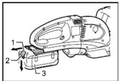
Installing or removing battery cartridge
Fig.1
CAUTION:
- Always switch off the tool before installing or removing of the battery cartridge. - Hold the tool and the battery cartridge firmly when installing or removing battery cartridge. Failure to hold the tool and the battery cartridge firmly may cause them to slip off your hands and result in damage to the tool and battery cartridge and a personal injury.
To remove the battery cartridge, slide it from the tool while sliding the button on the front of the cartridge.
To install the battery cartridge, align the tongue on the battery cartridge with the groove in the housing and slip it into place. Insert it all the way until it locks in place with a little click. If you can see the red indicator on the upper side of the button, it is not locked completely.
CAUTION:
• Always install the battery cartridge fully until the red indicator cannot be seen. If not, it may accidentally fall out of the tool, causing injury to you or someone around you.
- Do not install the battery cartridge forcibly. If the cartridge does not slide in easily, it is not being inserted correctly.
Handle mounting positions
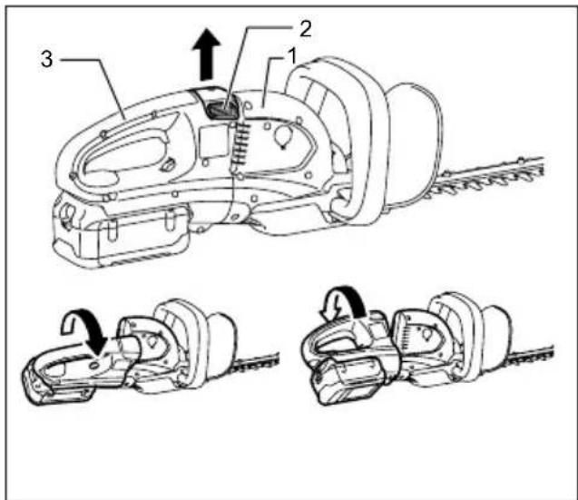
- Housing
- Knob
- Handle
011148
The handle can be rotated to either 90^ left or right and mounted either 45^ or 90^ position to fit your work needs. First, pull the knob and rotate the handle clockwise or counterclockwise in the direction of arrow as shown in the figure. The handle will be locked in 45^ position. The pull the knob and rotate more. The handle will be locked in 90^ position.
CAUTION:
• Always make sure that the handle is locked in the desired position before operation.
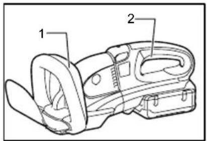
Switch action
CAUTION:
- Before inserting the battery cartridge into the tool, always check to see that the switch trigger actuates properly and returns to the "OFF" position when released.
Fig.2
For your safety, this tool is equipped with a dual switching system. To turn on the tool, press triggers A and B. Release either one of the two pressed triggers to turn off. The sequence of switching is unimportant as the tool only starts when both switches are activated.
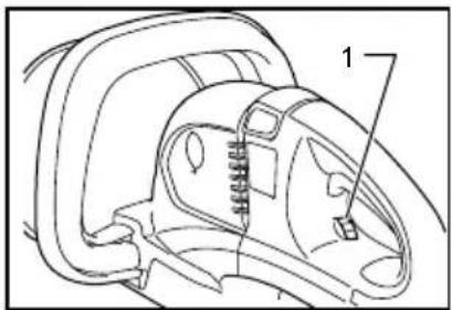
Speed change
Fig.3
The strokes per minute can be adjusted just by turning the adjusting dial. This can be done even while the tool is running. The dial is marked 1 (lowest speed) to 6 (full speed).
Refer to the table below for the relationship between the number settings on the adjusting dial and the strokes per minute.
| Number on adjusting dial | Strokes per minute (min)1 |
| 6 | 1,800 |
| 5 | 1,750 |
| 4 | 1,650 |
| 3 | 1,500 |
| 2 | 1,300 |
| 1 | 1,000 |
011264
CAUTION:
- The speed adjusting dial can be turned only as far as 6 and back to 1. Do not force it past 6 or 1, or the speed adjusting function may no longer work.
- The strokes per minute vary by the conditions of battery cartridge and shear blades.
Battery protection system
Lithium-ion batteries are equipped with a protection system. This system automatically cuts off power to the tool to extend battery life.
The tool will automatically stop during operation if the tool and/or battery are placed under one of the following conditions:
• Overloaded:
The tool is operated in a manner that causes it to draw an abnormally high current.
In this situation, release the switch trigger on the tool and stop the application that caused the tool to become overloaded. Then pull the switch trigger again to restart.
If the tool does not start, the battery is overheated. In this situation, let the battery cool before pulling the switch trigger again.
- Low battery voltage:
The remaining battery capacity is too low and the tool will not operate. In this situation, remove and recharge the battery.
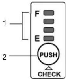
Battery remaining capacity indicator (only for models with Battery BL3622A)
Battery BL3622A is equipped with the battery remaining capacity indicator.
-
Indicator lamps
-
CHECK button
011715
Press the CHECK button to indicate the battery remaining capacity. The indicator lamps will then light for approx. three seconds.
| Indicator lamps | Remaining capacity |
| Lighted Off Blinking | |
| E F | 70% to 100% |
| 45% to 70% | |
| 20% to 45% | |
| 0% to 20% | |
| Charge the battery. | |
| The battery may have malfunctioned. |
011713
- When only the lowermost indicator lamp (next to the "E") blinks, or when none of the indicator lamps light, the battery capacity has run out, so the tool does not operate. In these cases, charge the battery or replace the empty battery with a fully charged one.
- When two or more indicator lamps do not light even after charging is complete, the battery has
reached the end of its service life.
- When the upper two and lower two indicator lamps light alternately, the battery may have malfunctioned. Contact your local Makita authorized service center.
NOTE:
- The indicated capacity may be lower than the actual level during use or immediately after using the tool.
- Depending on the conditions of use and the ambient temperature, the indication may differ slightly from the actual capacity.
ASSEMBLY
CAUTION:
• Always be sure that the tool is switched off and the battery cartridge is removed before carrying out any work on the tool.
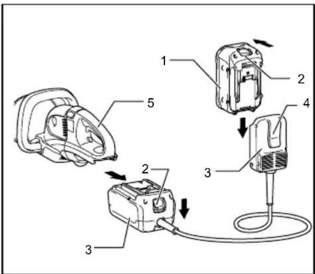
Battery adapter (Accessory)
-
Battery cartridge
-
Button
-
Adapter
-
Hook
-
Tool
011149
Fig.4
CAUTION:
- Before using battery adapter, read all instructions on tools using battery.
- When charging a battery cartridge, first remove it from the battery adapter and then charge it. It is not allowed to charge the battery cartridge while using battery adapter.
Installing or removing battery adapter
- Always switch off the tool before insertion or removal of the battery adapter.
- To remove the battery adapter, withdraw it from the tool while sliding the button on the adapter.
- To insert the battery adapter, align the tongue on the battery adapter with the groove in the housing and slip it into place. Always insert it all the way until it locks in place with a little click. If you can see the red part on the upper side of the button, it is not locked completely. Insert it fully until the red part cannot be seen. If not, it may accidentally fall out of the tool, causing injury to you or someone around you.
- Do not use force when inserting the battery adapter. If the adapter does not slide in easily, it is not being inserted correctly.
- The way of removing or installing a battery cartridge from or on the battery adapter is the same as that of removing or installing it from or on the tools.
- Press down the hook securely as far as it will go when the battery adapter is hooked on the waist belt and similar objects.
Arm cord hook (Accessory)
CAUTION:
- Do not attach the holder of arm cord hook to other than the extension cord. Failure to do so may cause an accident or personal injury.
Using the arm cord hook helps to minimize a risk of cutting off the extension cord unexpectedly caused by the loose extension cord.
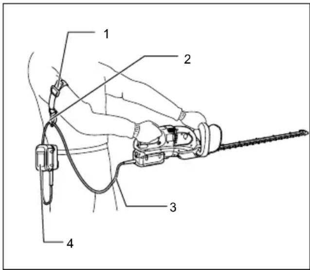
- Arm cord hook band
- Holder
- Extension cord (Battery adapter)
- Adapter (Battery adapter)
011150
Attach firmly the arm cord hook band placing around your arm and pass the extension cord through the holder. The length of the arm cord hook band is adjustable.
NOTE:
- Do not pass the extension cord through the band.
- Do not force the opening of the holder. Failure to do so may cause deflection and damage to it.
OPERATION
CAUTION:
- Be careful not to accidentally contact a metal fence or other hard objects while trimming. The blade will break and may cause serious injury.
• Overreaching with a hedge trimmer, particularly from a ladder, is extremely dangerous. Do not work from anything wobbly or infirm.
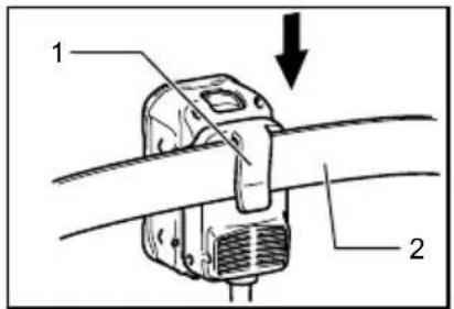
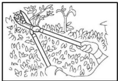
Fig.5
Do not attempt to cut branches thicker than 10 mm diameter with this trimmer. These should first be cut with shears down to the hedge trimming level.
CAUTION:
- Do not cut off dead trees or similar hard objects. Failure to do so may damage the tool.
Fig.6
Hold the trimmer with both hands and pull the switch trigger A or B and then move it in front of your body.
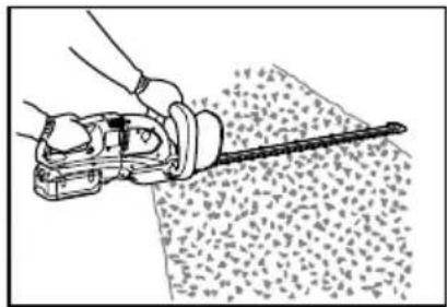
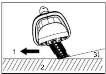
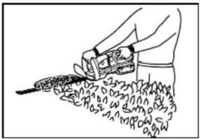
Fig.7
As a basic operation, tilt the blades towards the trimming direction and move it calmly and slowly at the speed rate of 3 - 4 seconds per meter.
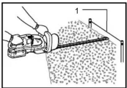
Fig.8
To cut a hedge top evenly, it helps to tie a string at the desired hedge height and to trim along it, using it as a reference line.
Fig.9
Attaching the chip receiver (accessory) on the tool when trimming the hedge straight can avoid cut off leaves' being thrown away.
Fig.10
Rotate the handle for your easy handling before operation. Refer to the section titled "Handle mounting position"
To cut a hedge side evenly, it helps to cut from the bottom upwards.
Fig.11
Trim boxwood or rhododendron from the base toward the top for a nice appearance and good job.
Installing or removing chip receiver (accessory)
CAUTION:
- Always be sure that the tool is switched off and the battery cartridge is removed before installing or removing chip receiver.
NOTE:
- When replacing the chip receiver, always wear gloves so that hands and face does not directly contact the blade. Failure to do so may cause personal injury.
- Always be sure to remove the blade cover before installing the chip receiver.
- The chip receiver receives cut-off leaves and alleviates collecting thrown-away leaves. This can be installed on either side of the tool.
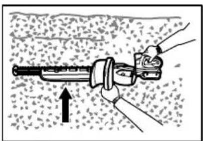
Fig.12
Press the chip receiver on the shear blades so that its slits overlap with the nuts on the shear blades. At this time, make sure that the chip receiver does not contact branch catcher at the top of the shear blades.
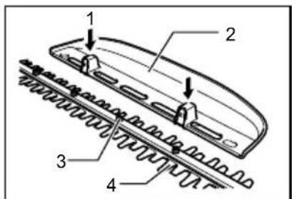
Fig.13
At this time, the chip receiver needs to be installed so that its hooks fit into grooves in the shear blade unit.
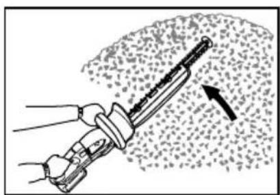
Fig.14
To remove the chip receiver, press its lever on both sides so that the hooks are unlocked.
Fig.15
⚠️CAUTION:
- The blade cover (standard equipment) cannot be installed on the tool with the chip receiver being installed. Before carrying or storing, uninstall the chip receiver and then install the blade cover to avoid blade exposure.
NOTE:
- Check the chip receiver for secure installment before use.
- Never try to uninstall the chip receiver by an excessive force with its hooks locked in the blade unit grooves. Using the excessive force may damage it.
MAINTENANCE
CAUTION:
- Always be sure that the tool is switched off and the battery cartridge is removed before attempting to perform inspection or maintenance.
Cleaning the tool
Clean out the tool by wiping off dust with a dry or soap-dipped rag.
CAUTION:
- Never use gasoline, benzine, thinner, alcohol or the like. Discoloration, deformation or cracks may result.
Blade maintenance
Smear the blade before and once per hour during operation using machine oil or similars.
NOTE:
- Before smearing the blade, remove the chip receiver.
After operation, remove dust from both sides of the blade with wired brush, wipe off it with a rag and then apply enough low-viscosity oil, such as machine oil etc. and spray-type lubricating oil.
CAUTION:
- Do not wash the blades in water. Failure to do so may cause rust or damage on the tool.
Removing or installing shear blade
CAUTION:
- Before removing or installing shear blade, always be sure that the tool is switched off and the battery cartridge is removed.
- When replacing the shear blade, always wear gloves without removing blade cover so that hands and face does not directly contact the blade. Failure to do so may cause personal injury.
NOTE:
- Do not wipe off grease from the gear and crank. Failure to do so may cause damage to the tool.
- For specific way of removing and installing shear blades refer to the reverse of a package for accessory shear blades.
Removing the shear blades
Reverse the tool and loosen four screws.
Fig.16
NOTE:
- Be careful not to get your hands dirty as grease is applied in the shear blade driving area.
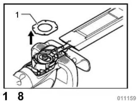
Remove the under cover.
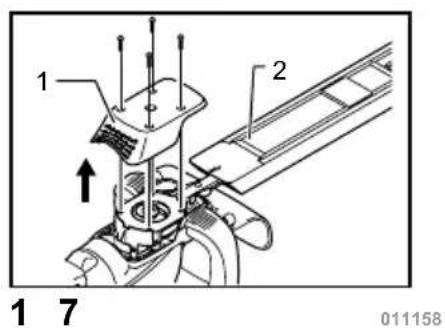
Fig.17
Remove the plate.
Fig.18
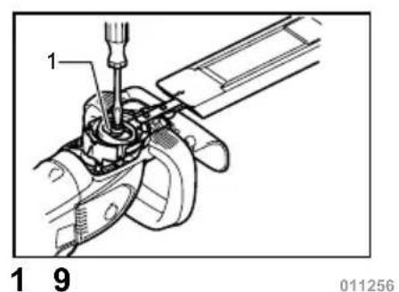
Set the crank at the angle as shown in the figure with a slotted bit screwdriver.
Fig.19
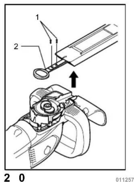
Remove two screws from the shear blades and the shear blade unit will be taken out.
Fig.20
CAUTION:
- Return the gear to the original position in such a manner as it was installed if it should be taken away by mistake.
Installing the shear blade
Prepare 4 removed screws (For under cover), 2 screws (For shear blade), plate, under cover, and new shear blades.
Adjust the crank position as shown in the figure. At this time, apply some grease provided with new shear
blades to the periphery of the crank.
Fig.21
Overlap the oval hole in the upper blade with that in the lower one.
Fig.22
Take out the blade cover from the old shear blades and fit it onto the new ones for easy handling during the replacement of blades.
Fig.23
Place the new shear blades on the tool so that the oval holes in the shear blades fit onto the crank. Overlap the holes in the shear blades with the screw holes in the tool and then secure them with two screws.
Fig.24
Check the crank for smooth turn with a slotted bit screwdriver.
Fig.25
Install the plate, under cover on the tool. Tighten the screw firmly.
NOTE:
- There is no distinction between the top and bottom of the plate.
Remove the blade cover and then turn on the tool to check it for proper movement.
NOTE:
- When the shear blades does not operate properly, there is a poor fit between the blades and crank. Redo from the beginning.
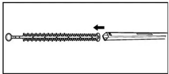
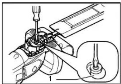
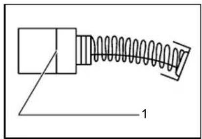
Replacing carbon brushes
Fig.26
Remove and check the carbon brushes regularly. Replace when they wear down to the limit mark. Keep the carbon brushes clean and free to slip in the holders. Both carbon brushes should be replaced at the same time. Use only identical carbon brushes.
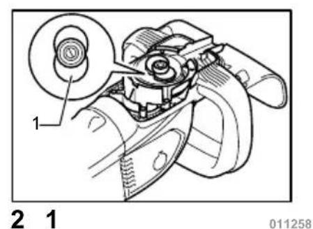
Fig.27
Insert the top end of slotted bit screwdriver into the notch in the tool and remove the holder cap cover by lifting it up.
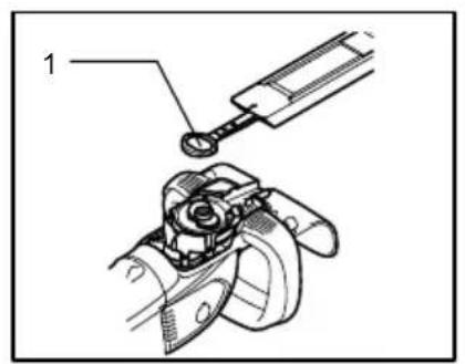
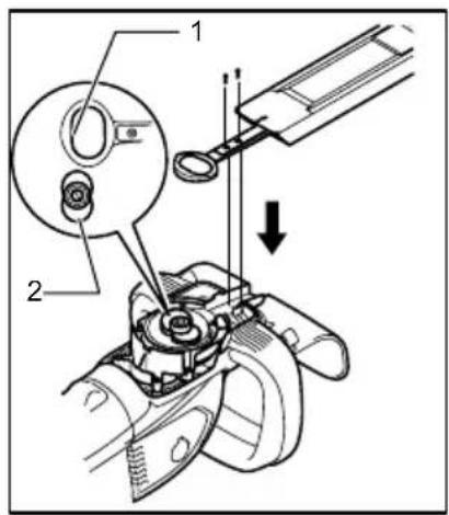
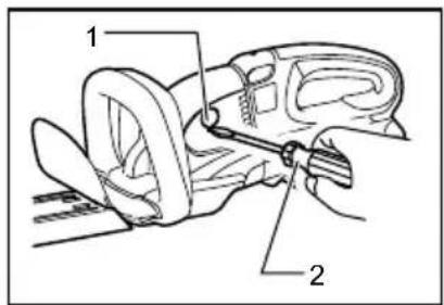
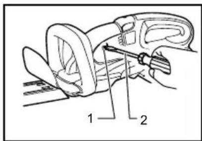
Fig.28
Use a screwdriver to remove the brush holder caps. Take out the worn carbon brushes, insert the new ones and secure the brush holder caps.
Reinstall the holder cap cover on the tool.
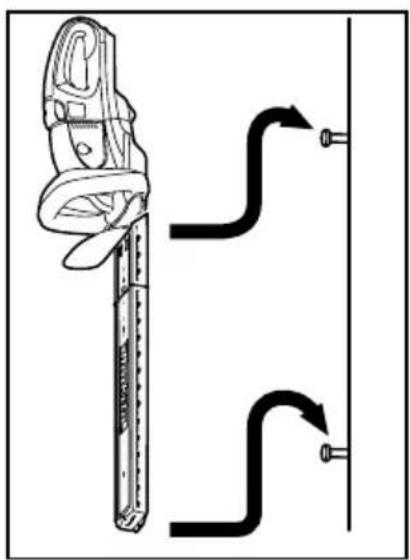
Storage
The hook hole in the bottom of the blade cover is convenient for hanging the tool from a nail or screw on the wall.
Fig.29
Remove the battery cartridge and put the blade cover on the shear blades so that the blades are not exposed.
Store the tool out of the reach of children carefully.
Store the tool in the place not exposed to water and rain. To maintain product SAFETY and RELIABILITY, repairs, any other maintenance or adjustment should be performed by Makita Authorized Service Centers, always using Makita replacement parts.
OPTIONAL ACCESSORIES
CAUTION:
• These accessories or attachments are recommended for use with your Makita tool specified in this manual. The use of any other accessories or attachments might present a risk of injury to persons. Only use accessory or attachment for its stated purpose.
If you need any assistance for more details regarding these accessories, ask your local Makita Service Center.
- Blade cover
- Shear blade assembly
- Makita genuine battery and charger
- Battery adapter
- Arm cord hook (to be used together with the battery adapter)
- Chip receiver
NOTE:
- Some items in the list may be included in the tool package as standard accessories. They may differ from country to country.
2000/14/EC, 2006/42/EC
Technical Department,
Michigan Drive, Tongwell,
Milton Keynes, Bucks MK15 8JD, Англія
3-11-8, Sumiyoshi-cho,
Anjo, Aichi, 446-8502, ЯПОНІЯ
GEA010-1
- Корпус
- Ручка
- Ручка
011148
Model BUH550, UH550D
Model BUH650, UH650D
2000/14/WE, 2006/42/WE
Model BUH550, UH550D
Model BUH650, UH650D
3-11-8, Sumiyoshi-cho,
Anjo, Aichi, 446-8502, JAPONIA
GEA010-1
-
Kontrolki
-
Przycisk CHECK (SPRAWDŻ)
011715
2000/14/EC, 2006/42/EC
Technical Department,
Michigan Drive, Tongwell,
Milton Keynes, Bucks MK15 8JD, Marea Britanie
Model BUH650, UH650D
3-11-8, Sumiyoshi-cho,
Anjo, Aichi, 446-8502, JAPONIA
GEA010-1
- Lămpi indicator
- Buton CHECK (Verificare)
011715
Modell BUH550,UH550D
Technical Department,
Michigan Drive, Tongwell,
Milton Keynes, Bucks MK15 8JD, England
3-11-8, Sumiyoshi-cho,
Anjo, Aichi, 446-8502, JAPAN
GEA010-1
- Gehäuse
- Knopf
- Griff
011148
-
Anzeigelampen
-
Taste CHECK
011715
2000/14/EK, 2006/42/EK
Technical Department,
Michigan Drive, Tongwell,
Milton Keynes, Bucks MK15 8JD, Anglia
3-11-8, Sumiyoshi-cho,
Anjo, Aichi, 446-8502, JAPÁN
GEA010-1
Technical Department,
Michigan Drive, Tongwell,
Milton Keynes, Bucks MK15 8JD, Anglicko
Model BUH550, UH550D
Model BUH650, UH650D
3-11-8, Sumiyoshi-cho,
Anjo, Aichi, 446-8502, JAPONSKO
GEA010-1
TIETO POKYNY USCHOVAJTE.
⚠️VAROVANIE:
DÔLEŽITÉ BEZPEČNOSTNÉ POKYNY
PRE JEDNOTKU AKUMULÁTORA
TIETO POKYNY USCHOVAJTE.
- Skriňa
- Gombík
- Rúčka
011148
-
Kazeta akumulátora
-
Tlačidlo
-
Adaptér
-
Hák
-
Náradie
011149
Fig.4
⚠POZOR:
Model BUH550, UH550D
Model BUH650, UH650D