Portland LG34-4P - Faucet Pfister - Free user manual and instructions
Find the device manual for free Portland LG34-4P Pfister in PDF.

User questions about Portland LG34-4P Pfister
0 question about this device. Answer the ones you know or ask your own.
Ask a new question about this device
Download the instructions for your Faucet in PDF format for free! Find your manual Portland LG34-4P - Pfister and take your electronic device back in hand. On this page are published all the documents necessary for the use of your device. Portland LG34-4P by Pfister.
USER MANUAL Portland LG34-4P Pfister
natural_image
Illustration of four different kitchen faucet fixtures (no text or symbols present)
Pfister™
Lifetime Limited Mechanical & Pfinish Warranty Covers Pfinish and Pfunction for as Long as You Own Your Home
(Commercial Applications Limit the Duration of the Warranties as Provided Below)
Pfister provides the following Warranties for its products. Proof of Purchases may be required in order to obtain any of the benefits set forth below.
Limited Warranties: Pfizer warrants that for as long as the original purchaser owns the home in which the Pfizer product (the "Product") is originally installed, the Product will be free of all defects in material and workmanship that would impair the intended and proper use of the Product. If the Product is installed in a commercial application, the above mechanical warranty shall be limited for a period of ten (10) years from the date of purchase of the Product.
Pfister warrants against deterioration of the Product's finish for as long as the original purchaser owns the home in which the Product is originally installed. If the Product is installed in a commercial application, the above finish warranty for Products that do not contain the Pforever finish shall be limited to a period of five (5) years from the date of purchase.
Exclusive Remedy: In the event of any defect in the Product that breaches the foregoing warranties, Pfister, at its option, will repair or replace the defective part of the Product. Repair or replacement of the Product is the exclusive remedy.
For any remedy under this warranty, Pfister is to be notified describing the problem. In order to notify Pfister and receive assistance or service under this warranty, the original purchaser may: (1) call 1-800-Pfiacet (1-800-732-8238) for a consumer service representative who can assist you, or (2) write consumer service department c/o Pfister Inc., 19701 DaVinci, Lake Forest, CA 92610, and include a description of the problem, model number your name, address, phone number and approximate date of purchase, or (3) email Pfister's customer service department by going to www.pfisterfaucets.com, or (4) notify the location or distributor from which the Product was purchased. In any case, you may be required to return the Product to Pfister for inspection and proof of purchase may be required.
Limitations and Exclusions:
PFISTER WILL NOT BE LIABLE FOR ANY OTHER DAMAGES OR LOSSES, INCLUDING, BUT NOT LIMITED TO, INCIDENTAL AND/OR CONSEQUENTIAL DAMAGES, REGARDLESS OF THE LEGAL THEORY ASSERTED, INCLUDING ANY CLAIM OR BREAKIE OF WARRANTY HEREUNDER OR ANY OTHER CAUSE, AND WHETHER ARISING IN CONTRACT OR IN TORT (including negligence and strict liability).
Pfister has the right to discontinue or modify any product at any time. Some states do not allow limitations or exclusions of incidental or consequential damages, so the above limitations or exclusions may not apply to you. This warranty gives you specific legal rights, and you may also have other rights which vary from state to state.
The above warranties do not cover damage resulting from improper maintenance, repair, cleaning or installation, misuse, abuse, alterations, accidents or acts of God.

Pfister™
Thank you for purchasing this Pfister product. All Pfister products are carefully engineered, and factory tested to provide long trouble-free use under normal conditions. This product is easy to install using basic tools and our easy to follow illustrated instructions. If you have any questions regarding this product, call 1-800-Pfaucet (1-800-732-8238).
1 BEFORE PROCEEDING

WARNING: Read all the instructions completely before proceeding. Pfister recommends calling a professional if you are uncertain about installing this product! This product should be installed in accordance with all local and state plumbing and building codes.
natural_image
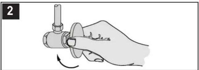
Hand holding a mechanical component with a rotating arrow indicating rotation (no text or symbols)2 SHUT OFF WATER SUPPLY
Locate water supply inlets and shut off the water supply valves. These are usually found under the sink or near the water meter. If you are replacing an existing faucet, remove the old faucet from the sink and clean the sink surface thoroughly.
natural_image
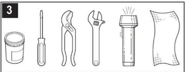
Line drawings of six different tools and objects: a paint can, screwdriver, pliers, wrench, flashlight, and fabric (no text or symbols)3 TOOLS RECOMMENDED
- Plumber's putty • Slotted screwdriver • Pliers - Adjustable wrench • Flashlight • Cloth Your installation may require new supply lines and/or shut-off valves or other additional tools.
text_image
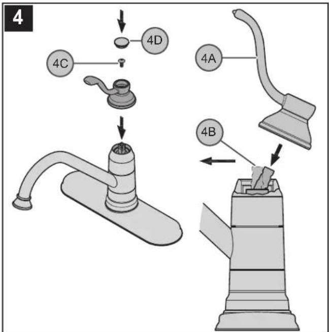
4 4C 4D 4A 4B4 HANDLE ATTACHMENT
Place Lever Handle (4A) onto Valve Stem (4B) and secure with Fastener (4C) as shown. Insert Decorative Button (4D) onto Lever Handle (4A).
FAUCET INSTALLATION
5
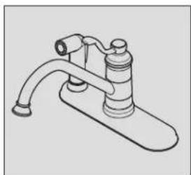
These instructions cover four different installations
natural_image
Line drawing of a kitchen faucet with handle and base (no text or symbols)Models 34-1P For 3 Hole Installation No Side Spray

natural_image
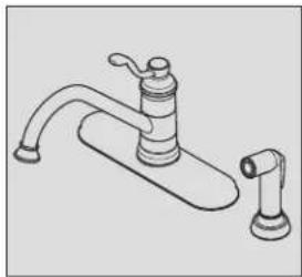
Line drawing of a kitchen faucet with handle and base (no text or symbols)Models 34-3P For 3 Hole Installation With Side Spray

natural_image
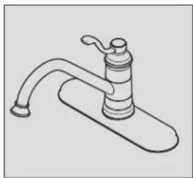
Line drawing of a kitchen faucet with handle and sink (no text or symbols)Models 34-4P For 4 Hole Installation With Side Spray

natural_image
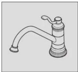
Line drawing of a standard kitchen faucet with handle and base (no text or symbols)Models 34-1P/34-4P Single Post Option Installation


text_image
6 6A 6B 6C6 FAUCET INSTALLATION
Following manufacturer's recommendations on use, apply plumber's putty into putty groove in Deck Plate (6A). Insert the faucet Supply Tubes (6B) through the center hole of the sink. Insert faucet Shanks (6C) through the end holes of the sink.
text_image
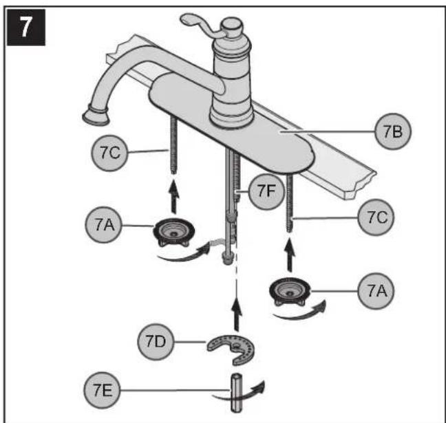
7 7C 7A 7F 7B 7C 7A 7D 7E7 SECURING FAUCET TO DECK
From underneath sink, hand tighten Wing Nuts (7A) to Mounting Posts (7C). Remove any excess putty from around the outside edge of Deck Plate (7B). Secure the faucet by placing the Metal Washer (7D) and the Long Nut (^7 / _16 Hex.) (7E) onto the Mounting Post (7F). Make sure that the bumps on the Metal Washer (7D) are facing up. Tighten until the faucet is firmly connected to the sink. Do not over tighten!

text_image
STOP Go To Step 17ENGLISH
text_image
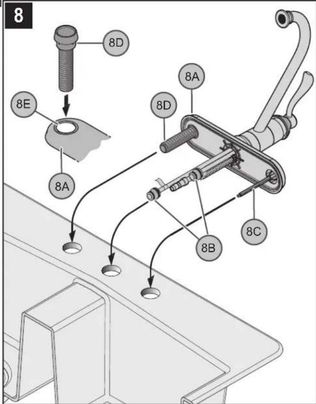
8 8D 8E 8A 8D 8A 8C 8B8 FAUCET INSTALLATION
Following manufacturer's recommendations on use, apply plumber's putty into putty groove in Deck Plate (8A). Insert Hose Guide (8D) into the Side Hole (8E) in the Deck Plate (8A). Align the hose guide Tabs to those in the Deck Plate Hole. Insert the faucet Supply Tubes (8B) through the center hole of the sink. Insert faucet Shank (8C) and Hose Guide (8D) through the end holes of the sink.
text_image
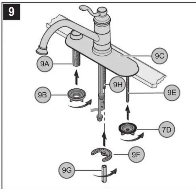
9 9A 9B 9C 9H 9E 7D 9F 9G9 SECURING FAUCET TO DECK
From underneath sink, secure the Hose Guide (9A) by screwing the Plastic Locknut (9B). Secure Deck Plate (9C) by screwing Wing Nut (9D) to Mounting Post (9E). Hand tighten. Remove any excess putty from around the outside edge of Deck Plate (9C). Secure faucet by placing the Metal Washer (9F) and the Long Nut ( ^7/_16 Hex.) (9G) onto Mounting Post (9H). Make sure that the bumps on the Metal Washer (9F) are facing up. Tighten until the faucet is firmly connected to the sink. Do not over tighten!
text_image
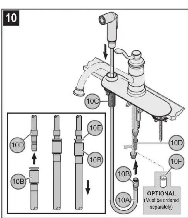
10 10C 10D 10E 10B 10D 10F 10B 10A OPTIONAL (Must be ordered separately)10 SIDE SPRAY INSTALLATION
Insert Side Spray Hose (10A) through Hose Guide (10C). From underneath sink, push Quick Connect Housing (10B), located on the end of the Spray Hose (10A), firmly upward onto the receiving Tube (10D), until unable to push any further. Pull down on the quick connect housing (10B). If the housing and the Inner Collet (10E) separate slightly, but does not pull off the receiving Tube (10D), quick connect is secure. When installing without side spray, a Plug (10F) 972-044 must be used and is to be ordered separately.

text_image
STOP Go To Step 17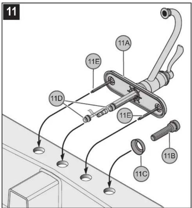
text_image
11 11A 11E 11D 11E 11B 11C11 FAUCET INSTALLATION
Following manufacturer's recommendations on use, apply plumber's putty into putty groove in Deck Plate (11A). Insert Hose Guide (11B) into Hose Guide Flange (11C) and onto the sink hole. Insert the faucet Supply Tubes (11D) through the center hole of the sink. Insert faucet Shanks (11E) through the end holes of the sink.
ENGLISH
text_image
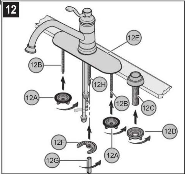
12 12B 12A 12H 12B 12C 12D 12F 12G 12A12 SECURING FAUCET TO DECK
From underneath sink, hand tighten Wing Nuts (12A) to Mounting Posts (12B), secure Hose Guide (12C) by screwing Plastic Locknuts (12D). Hand tighten. Remove any excess putty from around the outside edge of Deck Plate (12E). Secure the faucet by placing the Metal Washer (12F) and the Long Nut (7/16 Hex.) (12G) onto the Mounting Post (12H). Make sure that the bumps on the Metal Washer (12F) are facing up. Tighten until the faucet is firmly connected to the sink. Do not over tighten!
text_image
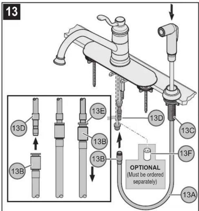
13 13D 13B 13E 13B 13D 13C 13F OPTIONAL (Must be ordered separately) 13A13 SIDE SPRAY INSTALLATION
Insert Side Spray Hose (13A) through Hose Guide (13C). From underneath sink, push Quick Connect Housing (13B), located on the end of the Spray Hose (13A), firmly upward onto the receiving Tube (13D), until unable to push any further. Pull down on the quick connect housing (13B). If the housing and the Inner Collet (13E) separate slightly, but do not pull off the receiving Tube (13D), quick connect is secure. When installing without side spray, a Plug (13F) 972-044 must be used and is to be ordered separately.

text_image
STOP Go To Step 17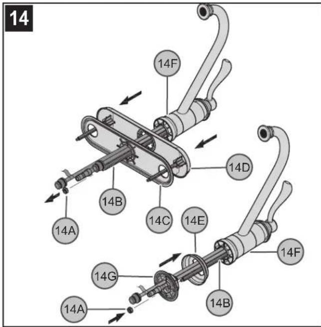
text_image
14 14F 14D 14B 14C 14E 14A 14G 14F 14A 14B14 FAUCET PREPARATION
From underneath faucet, remove Nut (14A) from Mounting Post (14B). Remove Putty Plate (14C) and Deck Plate (14D) from Faucet Body (14F). Assemble Mounting Ring (14E) and Putty Ring (14G) to Faucet Body (14F). Secure by placing and threading Nut (14A) onto Mounting Post (14B).
text_image
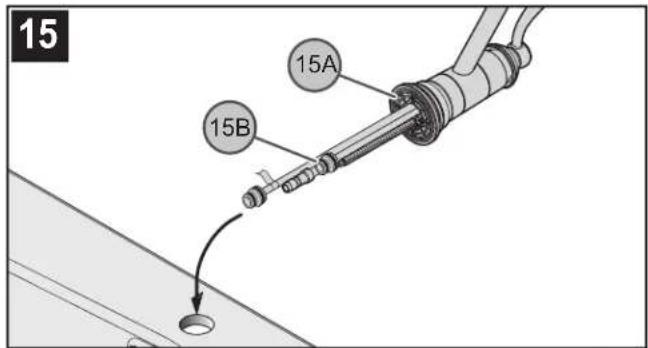
15 15A 15B15 FAUCET INSTALLATION
Following manufacturer's recommendations on use, apply plumber's putty into putty groove in Putty Ring (15A). Insert the faucet Supply Tubes (15B) through the center hole of the sink.
text_image
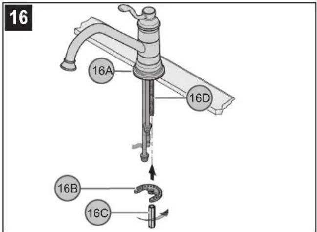
16 16A 16D 16B 16C16 SECURING FAUCET TO DECK
Remove any excess putty from around the outside edge of Mounting Ring (16A). From underneath sink, secure the faucet by placing the Metal Washer (16B) and the Long Nut (7 / 16 Hex.) (16C) onto the Mounting Post (16D). Make sure that the bumps on the Metal Washer (16B) are facing up. Tighten until the faucet is firmly connected to the sink. Do not over tighten!
ENGLISH
text_image
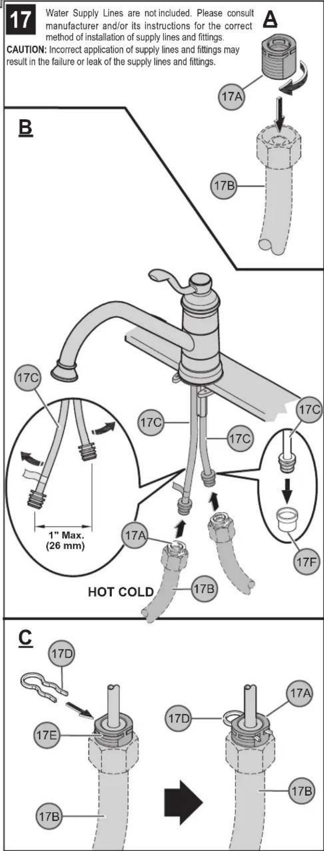
17 Water Supply Lines are not included. Please consult manufacturer and/or its instructions for the correct method of installation of supply lines and fittings. CAUTION: Incorrect application of supply lines and fittings may result in the failure or leak of the supply lines and fittings. A 17A 17B B 17C 17C 17C 17C 17A 17F 17B 17D 17E 17D 17A 17B C17 WATER SUPPLY CONNECTIONS
A. Thread Inlet Connectors (17A) into Water Supply Lines (17B).
B. Remove Protective Cap (17F). Gently separate hot and cold Faucet Inlets (17C), approximately 1 in. (26 mm) apart. Connect Water Supply Lines (17B) onto Faucet Inlets (10C). Hot water supply line goes to hot inlet fitting indicated by red tag.
C. Insert Clip (17D) into Inlet Connector Holes (17E) to secure water supply lines, as shown.
18
natural_image
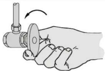
Illustration of a hand holding a mechanical component with a valve and shaft (no text or symbols)18 UNIT START UP
Turn on hot and cold water supplies, and check for leaks above and below the sink.
Note: After installation is complete, flush faucet (see step 22).
FAUCET FUNCTIONS
19
text_image
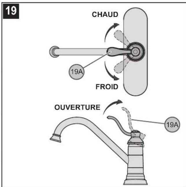
HOT 19A COLD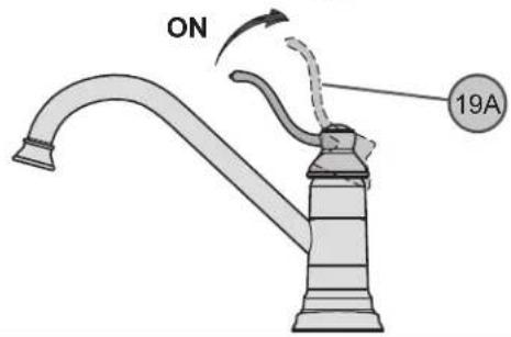
text_image
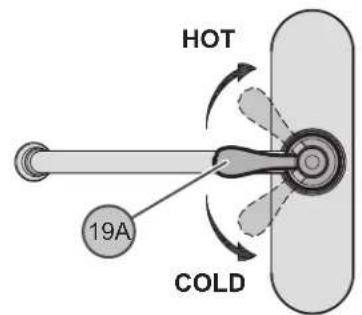
ON 19A19 VALVE FUNCTION
By lifting the Lever Handle (19A) up, the valve will be activated allowing water to flow. The water flow will increase by continuing to lift up the Lever Handle (19A). By rotating the Lever Handle counter-clockwise, the water temperature will decrease to cold flow only. By rotating the Lever Handle clockwise, the water temperature will increased to hot flow only.
20
text_image
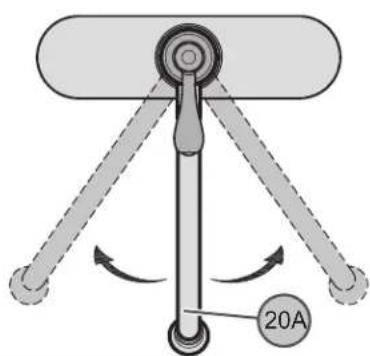
20A20 SPOUT FUNCTION
The Spout (20A) can be rotated around the Faucet Body in any direction.
ENGLISH
21
text_image
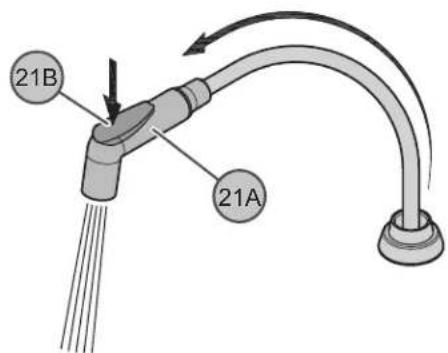
21B 21AThe Side Spray (21A) can be pulled forward to spray water in any direction. To activate the Side Spray, press the Toggle Button (21B) located on the back of the Side Spray (21A).
MAINTENANCE & CARE
22
text_image
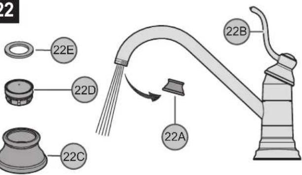
22 22E 22D 22C 22A 22B22 FLUSHING & AERATOR CLEANING
After installation is complete, remove Aerator Housing (22A). Turn Valve (22B) on and allow both hot and cold water to run for at least one minute each. While water is running, check for leaks. To clean the aerator, disassemble Aerator Housing (22A) by separating the Aerator Shell (22C), Basket (22D), and Washer (22E). Once parts have been cleaned, reassemble by reversing steps.
text_image
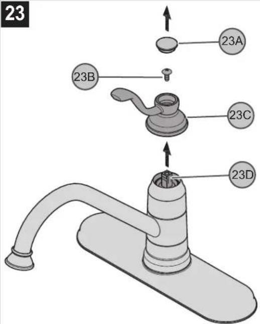
23 23A 23B 23C 23D23 HANDLE REMOVAL
Turn off water before proceeding! With valve in closed position, detach Decorative Button (23A), unscrew Fastener (23B), and remove Handle Hub (23C) from Valve Stem (23D).
text_image
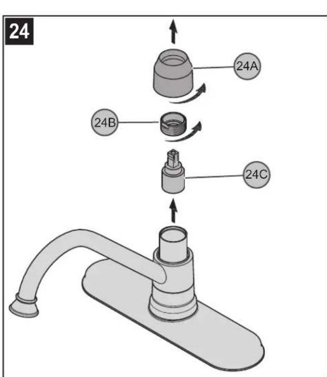
24 24A 24B 24C24 CARTRIDGE REMOVAL
Turn off water supplies and relieve pressure before working on your faucet (see step 2). Remove Handle (See step 23). Remove the Dome Cap (24A) by unscrewing it in a counterclockwise direction. Using an adjustable wrench, unscrew the Retainer Ring (24B). Carefully remove the Cartridge (24C) by pulling it straight up and out. Inspect Cartridge (24C) for debris or damage. Clean or replace the Cartridge (24C). Reassemble faucet by reversing steps.
text_image
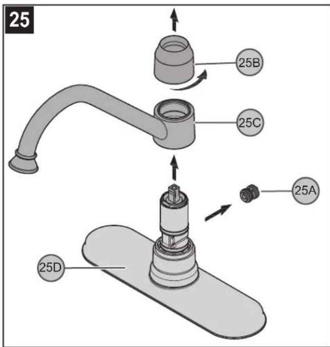
25 25B 25C 25A 25D25 DIVERTER REPLACEMENT
(For products with side spray). If the side spray fails to work properly the diverter mechanism may be clogged with debris or may need replacing. To check and/or replace Diverter (25A), shut off water supply and relieve pressure before working on your faucet (see step 2). Remove handle (see step 23) and Dome Cap (25B) and carefully lift up the Spout Assembly (25C). The Diverter Mechanism (25A) is located on the backside of Inner Faucet Body (25D). Carefully remove the Diverter Mechanism (25A) and check for debris. Clean or replace the Diverter Mechanism (25A). Reassemble faucet by reversing steps.
ENGLISH
text_image
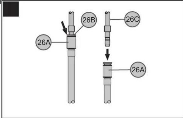
26A 26B 26C 26A26 SIDE SPRAY HOSE REMOVAL
Turn off water supplies and relieve pressure before working on your faucet. To remove the quick connect attachment, push up on the Quick Connect Housing (26A). Holding grey Plastic Colette (26B) in place, pull downward on Quick Connect Housing (26A) until Tube (26C) is free.

CAUTION: Maintenance
DISASSEMBLY
- Replacement parts may be available at the store where you purchased your faucet.
- When replacement parts are not available, please write or call Pfister Consumer Service.
- Always turn off water and relieve pressure before working on your faucet.

NOTE: Trim Care
Cleaning Instructions:
For all Handles and decorative finishes, use only a soft damp cloth to clean and shine. Use of polish, detergents, abrasive cleaners, organic solvents or acid may cause damage. Use of other than a soft damp cloth will nullify our warranty! Special Trim:
Trim products which contain Porcelain or other similar substance are not acceptable for public areas or Commercial use. Installation of Said Trim is at Users Risk!

1-800-PFAUCET (1-800-732-8238)
For Toll-Free Pfaucet information call 1-800-PFAUCET (1-800-732-8238) or visit www.pfisterfaucets.com
• Installation Support
• Care and Warranty Information
natural_image
Hand holding a mechanical component with a bolt and nut, showing a curved arrow indicating rotation (no text or symbols)natural_image
Line drawings of six different tools and objects: a jar, screwdriver, pliers, wrench, flashlight, and fabric (no text or symbols)natural_image
Line drawing of a kitchen faucet with handle and base (no text or symbols)natural_image
Line drawing of a kitchen faucet with handle and base (no text or symbols)natural_image
Line drawing of a kitchen faucet with handle and base (no text or symbols)natural_image
Line drawing of a faucet with handle and base (no text or symbols)natural_image
Illustration of a hand holding a mechanical component with a rotating arrow indicating rotation (no text or symbols)2 COUPURE DE L'ARRIVÉE D'EAU
natural_image
Line drawings of six different tools and objects: a jar, screwdriver, pliers, wrench, flashlight, and fabric (no text or symbols)natural_image
Line drawing of a kitchen faucet with handle and base (no text or symbols)Modèles 34-1P
natural_image
Line drawing of a kitchen faucet with handle and base (no text or symbols)Modèles 34-3P
natural_image
Line drawing of a kitchen faucet with handle and sink (no text or symbols)Modèles 34-4P
natural_image
Line drawing of a faucet with handle and base (no text or symbols)Modèles 34-1P/34-4P
natural_image
Illustration of a hand holding a mechanical component with a curved arrow indicating rotation (no text or symbols)18 MISE EN SERVICE DU MÉLANGEUR
FONCTIONNEMENT DES ROBINETS