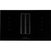
Aero 80 N A - Hob EICO - Free user manual and instructions
Find the device manual for free Aero 80 N A EICO in PDF.


| Product type | Induction hob with integrated hood |
| Brand | Eico |
| Model | Aero 80 N A |
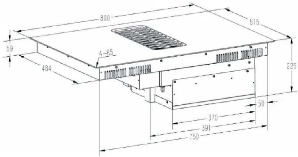
| Dimensions (W x D x H) | 80 x 52 x 5 cm (estimated) |
| Weight | Approximately 15 kg (estimated) |
| Power supply | 230 V / 50-60 Hz, 7200 W (4 wires: L1 black, L2 brown, N blue, PE yellow-green) |
| Number of cooking zones | 4 (2 x 190x190 mm front, 2 x 190x190 mm rear) |
| Power per zone | Front/rear zones: 100-2000 W (booster 2800/2100 W); bridge mode: up to 3000 W (booster 3600 W) |
| Main functions | Booster, Bridge mode, timer (default and manual), minute timer, pause, child lock, AUTO hood mode |
| Integrated hood | Touch control, levels 1-9 + booster, AUTO mode linked to cooking zones |
| Maintenance and cleaning | Clean grease filters every 3 days; replace activated carbon filter; ceramic filter can be regenerated (45 min at 200 °C); clean surface after each use |
| Safety | Child lock, residual heat indicator "H", automatic shutdown if inactive, overheating protection (E1, E2), low/high voltage protection (E3, E4) |
| Spare parts and repairability | Grease filters, activated carbon filter, ceramic filter, sealing tape, mounting brackets; contact customer service (www.eico.eu) |
| General information | Household use only; do not use with external timer; WEEE declaration; ERP, LVD, EMC standards |
Frequently Asked Questions - Aero 80 N A EICO
User questions about Aero 80 N A EICO
0 question about this device. Answer the ones you know or ask your own.
Ask a new question about this device
Download the instructions for your Hob in PDF format for free! Find your manual Aero 80 N A - EICO and take your electronic device back in hand. On this page are published all the documents necessary for the use of your device. Aero 80 N A by EICO.
USER MANUAL Aero 80 N A EICO
EN - Instruction on mounting and use
Induction hob with Integrated Extractor
natural_image
3D rendering of a mechanical or electronic component with layered structure (no visible text or symbols)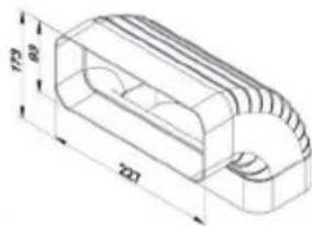
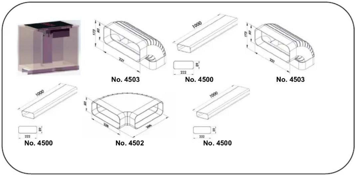
No. 4503
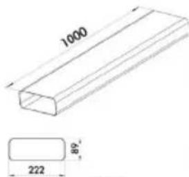
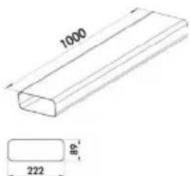
No. 4500
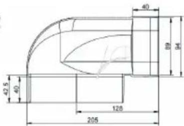
No. 2030
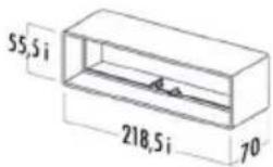
No. 4855
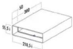
No. 4851
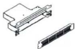
natural_image
Technical line drawing of a mechanical component with two views (top and side), no text or symbols present.No. 324-KRFH6
Re-circulation B
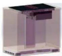
natural_image
3D rendering of a mechanical assembly or enclosure with no visible text or symbols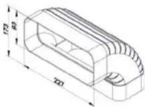
natural_image
Technical drawing of a mechanical part with dimension annotations (no readable text or symbols)No. 4503
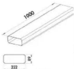
No. 4500
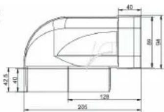
No. 2030
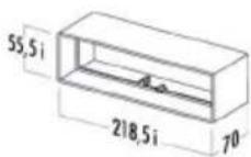
No. 4855
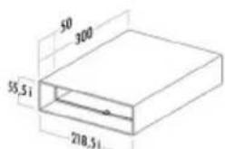
No. 4851
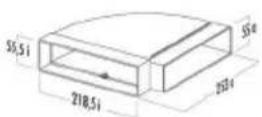
No. 4856
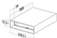
No. 4851
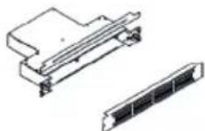
No. 324-KRFH6
Re-circulation C
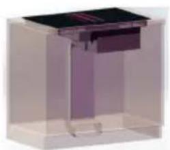
natural_image
3D rendering of a rectangular electronic device with a dark top and internal structure, enclosed in a transparent enclosure (no text or symbols visible)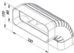
No. 4503
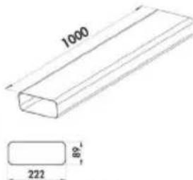
No. 4500
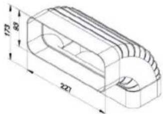
No. 4503
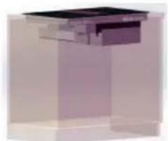
Extraction A
natural_image
3D rendering of a mechanical component or housing with no visible text or symbols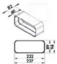
No. 4505
No. 4500
Extraction B
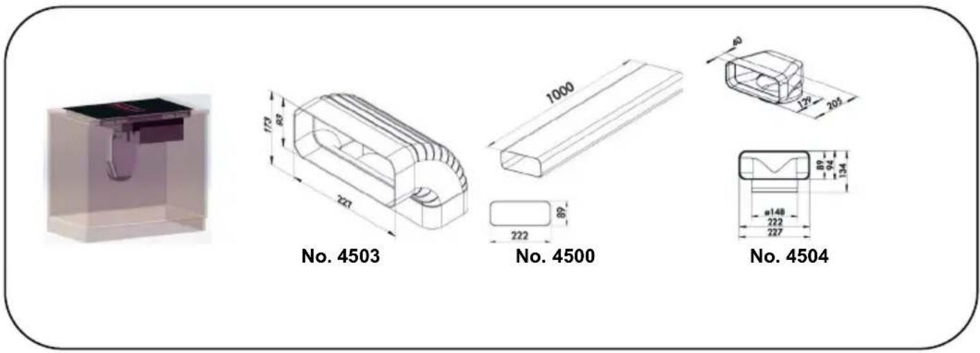
Extraction C
CONTENTS
- Always pay attention to....2
2.Warnings....2 - Using the hob....5
- Energy saving advice....5
- Included in the box....6
- Product overall dimension....7
- How to install the product....7
- Recommend Cooking Zone used for the pot.....10
- How to use the control panel....12
- Care and Maintenance....18
- Trouble Shooting....20
- Customer Care service.... 20
1. Always Pay attention to
Please strictly observe the instructions in this manual and keep this user manual for necessary reference in the future.
No liability will be assumed for any problems, damage or fires caused by failure to comply with the instructions in this manual.
The device is intended for domestic use only, to cook food and extract the fumes generated by cooking. No other use is allowed (ex. heating rooms). The manufacturer declines any liability for inappropriate use or incorrect setting of the controls.
The product may have different aesthetic features with respect to the illustrations in this handbook, however the operating, maintenance and installation instructions remain the same.
This manual must be stored for future consultation at any time. If sold, transferred, or moved, it must remain with the product.
! Read the instructions carefully: they contain important information on installation, operation, and safety.
! Do not make electrical changes to the product.
! Before installing the device, check that none of the components are damaged. Otherwise, contact the dealer and do not continue with the installation.
! Check the condition of the product for damages prior to its installation. Otherwise, contact the dealer and do not continue with the installation.
Note: The parts marked with the symbol "(*)" are optional accessories supplied only with some models or otherwise not supplied, but available for purchase.
The product does not have a plug, so an all-pole disconnect circuit breaker with an opening distance for more than 3mm needs to be installed near the installation position of the induction hob with integrated extractor. It is recommended to use a circuit breaker with a rated total current of at least 48A (16A for each phase) to make full use of the product performance.
2. Warnings
Caution! Strictly observe the following instructions:
- The device must be disconnected from the electrical network before performing any installation work.
- Installation or maintenance must be performed by a qualified technician, in compliance with the manufacturer's instructions and with local safety regulations. Do not repair or replace any part of the device unless specifically stated in the operating manual.
- Earthing the device is compulsory.
- The power cable must be long enough to allow the device, built-in to the cabinet, to be connected to the electrical network.
- To ensure the installation complies with current safety standards, a regular omni polar switch is required that assures the complete disconnection of the mains under category III over-voltage conditions, in accordance with the installation rules.
- Do not use multiple sockets or extension cords.
- Once installation is complete, the electrical components must no longer be accessible by the user.
- The device and its accessible parts heat up during use. Be careful not to touch the heated elements.
- Ensure that children do not play with the device; keep children away and supervise them, as the accessible parts may become very hot during use.
- For people with pacemakers and active implants it is important to check, prior to using the induction hob, that their pacemaker is compatible with the device.
- During and after use, do not touch the heating elements of the device.
- Avoid contact with cloths or other flammable materials until all the device components have sufficiently cooled.
- Do not place flammable materials on or near the device.
- Overheated fats and oils easily catch fire. Supervise the cooking of foods rich in fat and oil. Unattended cooking on a hob with oil or fat may be dangerous and may cause a fire.
- If the surface is cracked, switch off the device to avoid the possibility of an electric shock.
- The device is not intended to be run with an external timer or a separate remote-control system.
- The cooking process must be supervised. A short-term cooking process must be constantly monitored.
- Never attempt to put fires out using water. Instead, turn off the device and smother the flames, for example with a lid or a fire blanket. Fire hazard: do not rest objects on the cooking surfaces.
- Do not use steam cleaners.
- Do not place metal objects such as knives, forks, spoons, and lids on the hob surface as they may overheat.
- Before connecting the device to the electrical network: check the data plate (on the bottom of the device) to ensure that the voltage and power correspond to the network values and that the connection socket is suitable. If in doubt, consult a qualified electrician.
Important:
After use, switch off the hob from its control device and do not rely on the pot detector.
- Avoid spills; when boiling or heating liquids, lower the heat supply.
Do not leave the heating elements on with pots and pans empty or without containers.
Once cooking is complete, turn off the relative zone.
- Never use aluminum foil to cook with, and never directly place products packaged with aluminum on top of the cooking surface. The aluminum would melt and create irreparably damage your device.
-Never heat a tin or a tin can containing foods without first opening it: it might explode!
This warning also applies to all other types of hobs.
- A high power level such as the Booster function should not be used to heat certain liquids such as oil for frying.
Excessive heat may be dangerous. In these cases, we recommend the use of a lower power level.
- The containers must be placed directly on the hob and should be centered on one of the cooking zones.
Under no circumstances may anything be inserted between the pot and the hob.
- In high temperature situations, the device automatically decreases the power level of the cooking zones.
Before performing any cleaning or maintenance, disconnect the product from the electrical network by detaching the plug or disconnecting the home's master switch.
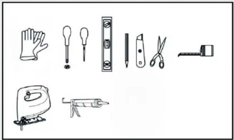
For all installation and maintenance operations, always use work gloves.
The device can be used by children 8 years or older and by persons with physical, sensory, or mental impairments, or by people without any experience or the necessary knowledge, provided they are supervised or have received instructions regarding the safe use of the device and provided they have a thorough understanding of the associated risks.
Children must be supervised to ensure they do not play with the device.
Cleaning and maintenance must never be performed by children unless they are properly supervised.
The room must be properly ventilated when the cooker hood is used at the same time as other combustion devices, gas or otherwise.
The hood must be regularly cleaned both internally and externally (AT LEAST ONCE PER MONTH), in strict accordance with the maintenance instructions.
Failure to follow the rules for cleaning, filter replacement and cleaning shall result in a fire hazard.
It is strictly prohibited to flame food.
The use of an open flame may damage the filters and cause a fire hazard; it must therefore be avoided under all circumstances.
Extra care must be taken when frying to prevent the oil from overheating and catching fire.
CAUTION: When the hob is on, the accessible parts of the hood may become hot.
CAUTION: Do not connect the device to the electrical network until installation is entirely complete.
Regarding the technical and safety measures that must be adopted for fume extraction, regulations issued by local authorities must be strictly followed.
The extracted air must not be conveyed through the same ducts used to extract the fumes generated by gas combustion or other types of combustion devices.
Never use the hood unless the grill has been correctly assembled!
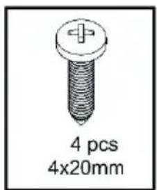
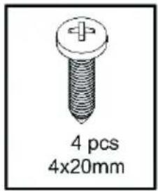
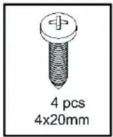
Use only the fastening screws supplied with the product for its installation, or if not supplied, purchase the correct type of screws. Use screws with the right length, as indicated in the installation guide.
When the cooker hood is used together with other devices powered with non-electrical energy, the negative pressure of the room must not exceed 4 Pa (4 x 10⁻⁵ bar).
This device is marked in compliance with 2012/19/EU Waste Electrical and Electronic Equipment (WEEE).

The WEEE symbol ■ on the product or accompanying documentation indicates that this product should not be treated as household waste but should be handed over at a suitable collection point for the recycling of electrical and electronic equipment. Dispose of the device in accordance with local regulations on waste disposal. For further information about the treatment, recovery, and recycling of this product, please contact your local authority, a collection service for household waste or the shop where the product was purchased. By ensuring that this product is disposed of correctly, the user will help prevent potential negative consequences for the environment and human health.
Regulations:
Device designed, tested and developed in compliance with regulations on:
-ERP: EN IEC 61591:2020+A11:2020, EN IEC 60704-1:202, EN 60704-2-13:2017, EN 50564:2011.
-LVD: EN 60335-2-31:2024+A11:2023+A1:2023+A2:2023, EN 60335-2-6:2015+A1:2020+A11:2020, EN 60335-1:2012+A11:2024+A13:2017+A1:2019+A14:2019+A2:2019+A15:2021+A16:2023, EN 62233:2008.
-EMC: EN IEC 55014-1:2021, EN IEC 55014-2:2021, EN IEC 61000-3-2:2019+A1:2021, EN 61000-3-3:2013+A1:2019+A2:2021,CISPR 16-2-1:2014+A1:2017, CISPR 16-2-3:2016+A1:2019, EN 61000-4-3:2020, EN 61000-4-4:2012, EN 61000-4-5:2014+A1:2017, EN 61000-4-6:2014, EN IEC 61000-4-11:2020.
3. Using the hob
The induction cooking system is based on the physical phenomenon of magnetic induction. The main characteristic of this system is the direct transfer of energy from the generator to the pot.
Advantages:
When compared to electric hobs, your induction hob is:
- Safer: lower temperature on the glass surface.
- Faster: shorter food heating time.
- More accurate: the hob immediately reacts to your commands
- More efficient: 90% of the absorbed energy is transformed into heat. Moreover, once the pot is removed from the hob, heat transmission is immediately interrupted, avoiding unnecessary heat losses.
Using of Pots:
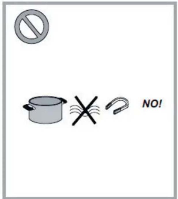
Use only pots bearing the induction symbol

Important: to avoid permanent damage to the hob surface, do not use:
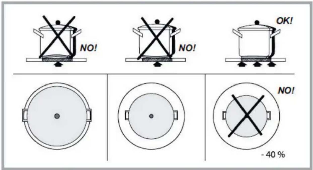
- Containers with less than perfectly flat bottoms.
- Metal containers with enameled bottoms.
- Containers with a rough base, to avoid scratching the hob surface.
- Never place hot pots and pans on the surface of the hob's control panel.
Pre-existing cookware:
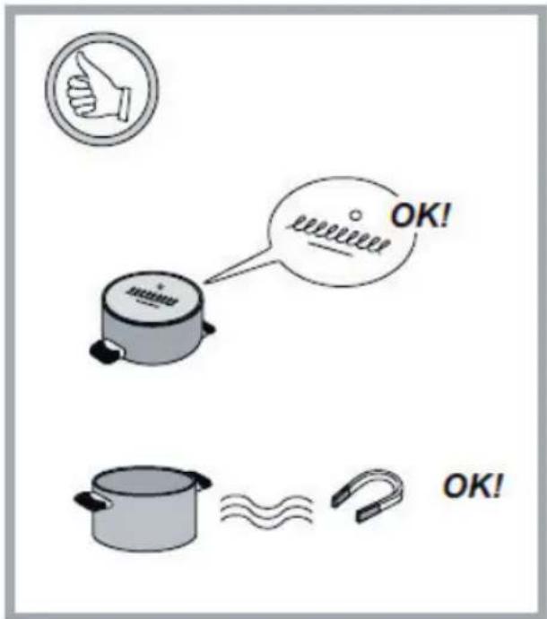
Induction cooking uses magnetism to generate heat. Containers must therefore contain iron. Check if the pot material is magnetic using a magnet. Pots are not suitable if they are not magnetically detectable.
Recommended pan bottom diameters:
IMPORTANT: if the pots are not correctly sized, the cooking zones will not turn on.
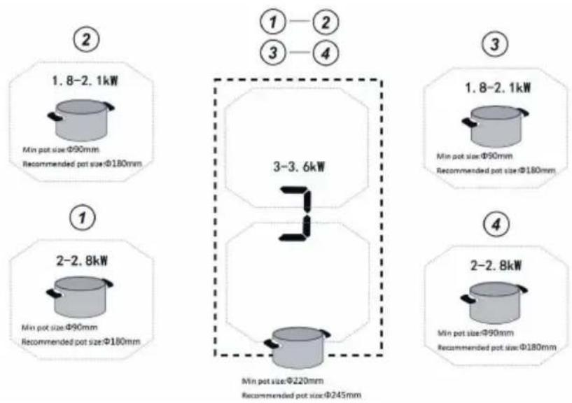
For details of the minimum pot diameter that needs to be used on each cooking zone, see figure 8 and figure 9.
4. Energy saving advice
Recommendations for best results:
- Use pots and pans with a bottom diameter equal to that of the cooking zone.
- Use only pots and pans with flat bottoms.
- Where possible, keep the lid on pots during cooking
- Cook vegetables, potatoes, etc. with a small amount of water to reduce cooking time.
- Use a pressure cooker, it further reduces the energy consumption and cooking time
- Place the pot in the center of the cooking zone drawn on the hob surface.
5. Included in the box
natural_image
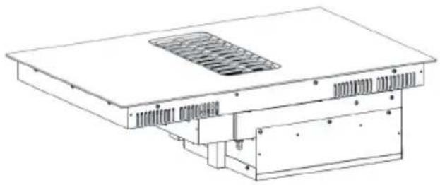
Technical line drawing of a mechanical or electrical component with no visible text or symbols1 pc - Induction hob with integrated extractor
natural_image
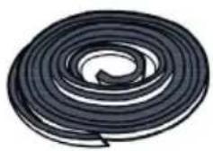
Spiral black-and-white illustration of a coiled cable or wire (no text or symbols)1 pc - Seal Tape
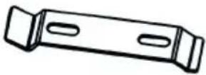
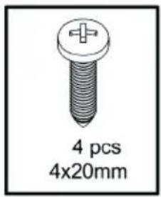
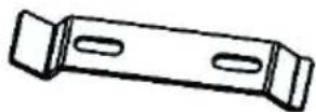
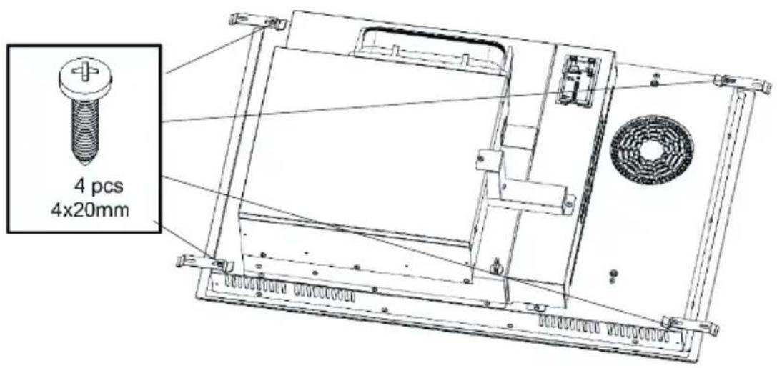
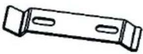
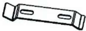
4 pcs Brackets
Installation tools needed:
natural_image
Collection of hand tools including gloves, screwdriver, roller, and spray can (no text or labels)6. Product Overall Dimension
7. How to install the product
Cabinet cut our dimensions:
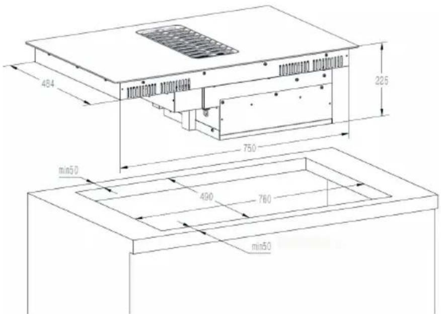
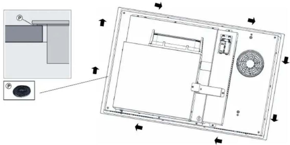
Add the seal tape at the edge of the back side of the product before putting into cabinet.
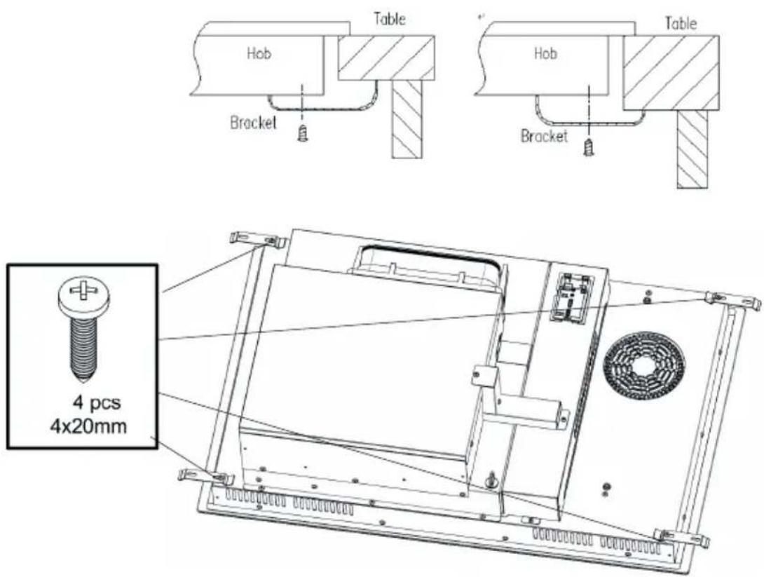
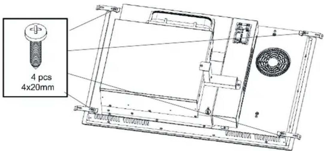
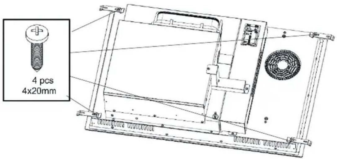
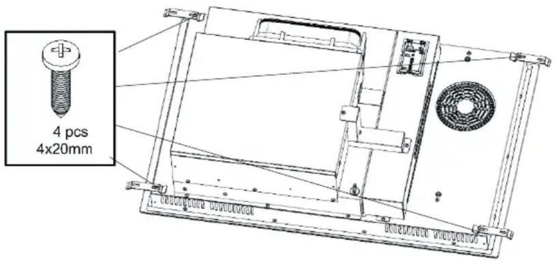
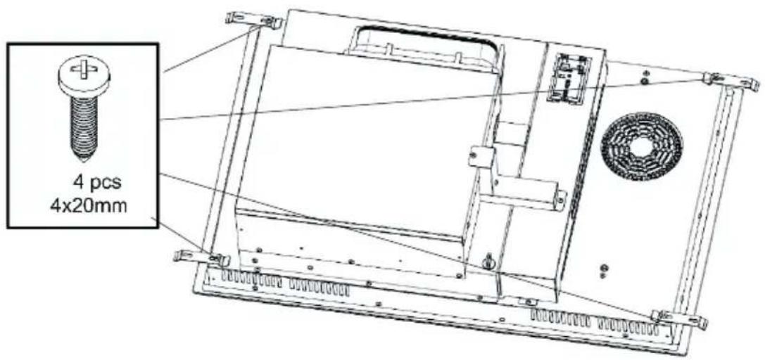
Fix the hob on the cabinet surface with the 4 brackets, included in the box, on the bottom of the hob (see picture) after the installation. Adjust the bracket position to suit different cabinet surface thicknesses.
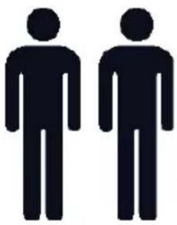
To finish the installation, we recommend 2 installers to easier place the product in position.
natural_image
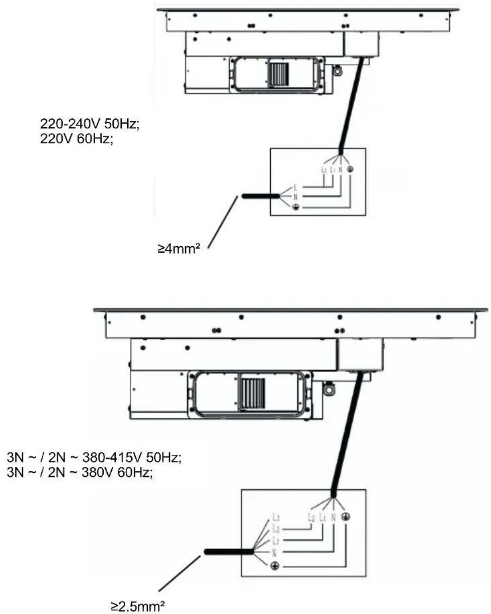
Two identical black silhouette figures of men, no text or symbols presentThe product has 4 cables, L1 black color, L2 brown color, Neutral blue color and earthing yellow-green color. The product is suitable to be connected in one of the ways of following two pictures, according to the user's grid configuration.
Electricity must be disconnected during Cable connection.
8. Recommend Cooking Zone to be used for the pot
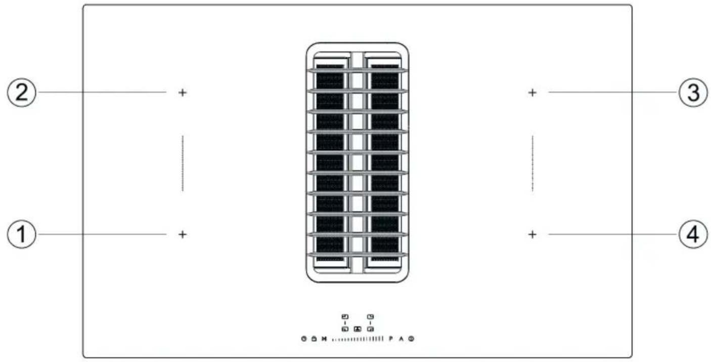
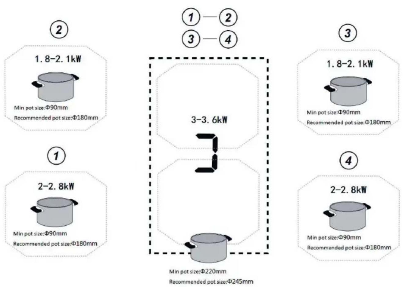
Fig 8

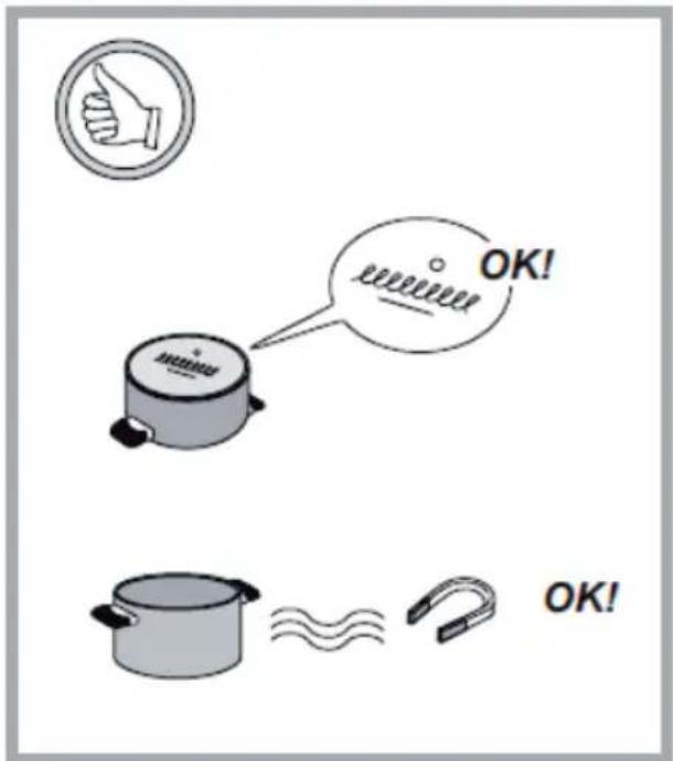
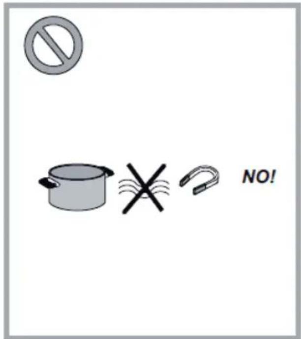
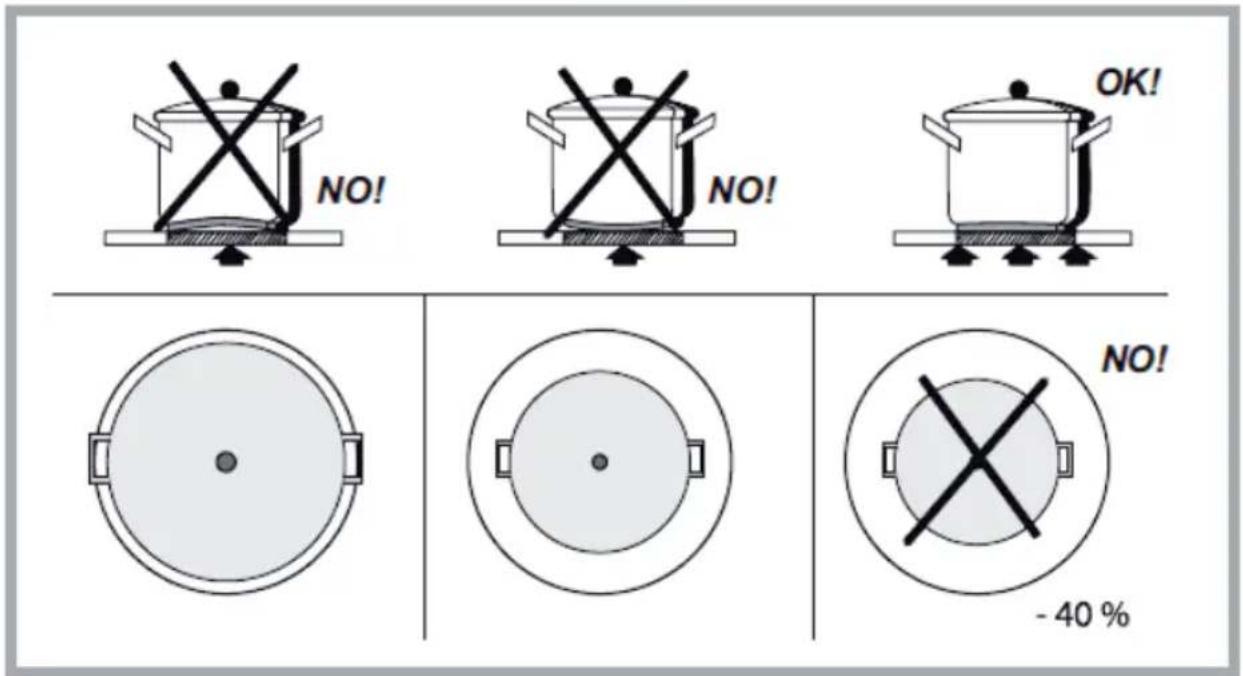
Fig 9
9. How to use the control panel
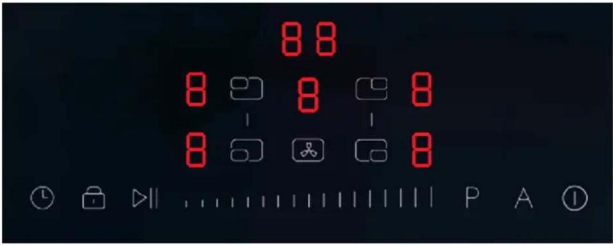
Switch on the product: In off mode, long press 3 second (1), the buzzer will beep 1 time. All display for induction will show “-”, and the cooker hood display will show “-”, meaning the product is waiting for next step to be set. If there is no further setting on display after 60s, the production will switch off automatically, and the buzzer will beep 1 time.
Switch off the Induction: During induction is working on, by Press ①, all induction zones will stop the cooking, and the hoods would automatically step to the 1^st level and continue to run for 10 minutes before switching off automatically. During the period of the 10 minutes, if wishing to switch off before automatic
switch off, touch the Ⓐ button again, or you can touch the "fan symbol 🎥 and slide 🌈 to the "0" position.
When switching off the induction, all heating areas stop. It will have the residual heat indicator, so the display will show "H". When there is no residual heat indication, "H" showing in the display, the induction cooker cooling fan will automatically turn off.
If a pot, liquid or similar is touching the control panel, and one or more other keys are being pressed a longer period, a touch on the 📄 button can only switch off the product, but not turn on the product.
Adjust the heating for inductions: First touch the zone key to select the corresponding heating zone, the
display for the selected zone will flash 0, and user can adjust the level by sliding [icon: 1] to the left means "-", and sliding to the right means "+". The display does not flash during operation.
You can set level 0-9, and the set number of level will be displayed in the window for its area. After 5 seconds the set level will be fixed in the display and the display will stop flashing.
Remarks: After 5 seconds pass over, and the set level is fixed, it would need to repeat the same operation to start the induction zone.
Booster Function: First press the zone key to select the heating zone. The display for the selected zone
will flash 0, then touch the P, and the specified heating zone will enter Booster mode. The display will flash 'P'. After 5 seconds, the P will confirm by stop flashing. (Booster mode can also be accessed from other power level settings)
End the Booster Function: First press the zone key to select the corresponding heating zone, the display
for the selected zone will be flashing. Then touch the right end of ____. When the display show '9', then it means the booster mode ended.
Remarks: The booster mode can work only 5 minutes. After that, it jumps to level 9 automatically. If
repeatedly touching the P while running in P mode, it will not change any settings.
Child Lock: When the product is in working mode, touch 📄, and the product will activate the child lock. The buzzer will beep 1 time, and the timer display will show 'Lo' for 2 seconds. If any keys is touched, the timer display will show 'Lo' for 2 seconds again.
Turn off child-lock: When the product is locked, by long press on for 2 seconds, the induction hob will exit the locked state with a short beep from the buzzer.
Remarks: When the product is locked, only the key and can be operated. Other keys are locked (The product can only be turned off, but not able to turn on when locked)
Pause function: When the product is working, by touching the key ▷, all the zones will stop heating. All the induction display windows will show ▪ at the same time (except for the hood display). With this pause, the default timer, the manual timer, and minute reminder will be suspended. The pause lasts for a maximum of 30 minutes, after that if no further activation, it would automatically switch off.
To end the pause function: When user will wish to restart the cooking, by touch the key ▷II, all the zones will continue to heat on the same power level, either the default timer, the customized timer or the minute minder will continue to run on the timing.
Timing Function: The Induction has 3 ways of timer, 1 is Default timer, 1 is Manual timer, and 1 is minute minder.
Default timer (ONLY for single cook zone): If customer don't set timer for each heating zone, the heating zone will start the default timer function, the default timer is different from each power level. When it reaches the default timer, the corresponding heating zone will be automatically turned off.
The Default timer and manual timer for each power level would be:
| Power level 1 2 3 4 5 6 7 | 8 9 | ||||||||
| Default timer (Minutes) | 360 | 360 | 360 | 180 | 180 | 180 | 120 | 120 | 90 |
| Manual timer (Minutes) 1-99 | |||||||||
Manual timer: When the induction is working, customer can set timer for each heating zone, several cook zone, or Bridged cooking areas.
When the timer reaches the set time, the corresponding heating zone will stop heating, and the buzzer will beep for 30 seconds. If the user operates the product within 30 seconds, the buzzer will stop beeping.
Steps for Manual timer operation: When a manual timer is about to be set for a SINGLE heating zone, first touch the zone selection key, and set for its cooking level. During the set level digit is flashing, by
touching the [icon] key, at this moment, the decimal point(.)in the lower right corner of the selected cooking zone display flashes, means that the action set has been successfully associated with the selected
heating zone. Then touch key to set minutes from 1,2,3,4...9 minutes. If wish to set timer
longer than 9 minutes, by touch the 📊 again. It can slide the timer for longer timing. When the operation is finished, the decimal light (.) in the lower right corner of the cooking zone display will be on. When the set cook time is finished, the timer display will show "00", the Induction zone will show "0". If setting more than 1 cooking zone's manual timer, the steps is same as above. The timer display will show for the zone whose set time is the shortest, until the timers finish for all cooking zones. During the manual timer's counting time, by touching zone key, it will show the set working time for this zone.
Minute reminder function: With at least one zone activated without the display flashing, touch the

key to set the minute minder function. When it reaches the set time, the buzzer will beep for 30 seconds, but the zone will not stop heating. If the user is operating the control panel, the buzzer will stop beeping.
Remarks: When the decimal point of the digital tube of the zone is flashing, it means that the current displayed time is the manual timing of the heating area. If the decimal point of the digital tube of the heating area is not flashing, it means the current display time is only the minute minder time. In the whole timing state, if you press the zone selection key to select the corresponding zone, the current timing digital tube currently displays the time for the current selection of the cooking zone.
Bridge Function: When the product is on, by touching the two zone selection keys at the same time (left front/left rear or right front/right rear combinations only) it will enter bridge mode,
The keys are in the following:
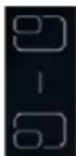
Left front/left rear zone
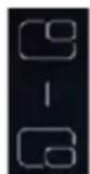
Right front/right rear zone

will be displayed in
When no pot is detected on both the upper and lower zones, the no pots symbol will be displayed in front left or front right zone's display, and the upper part of the no pots symbol, (U) will flash, the lower part "—" will not flash. There will be no change in the display of the left and right's rear zones.
To end the Bridge mode: During Bridge heating is on, simultaneously touch the two zone selection keys, to be able to end the bridge mode. Or by adjusting the power level to 0.
Adjust the power level for bridge function: During the bridge function, touch the zone selection key which needs to be adjusted (left front or right front), now the display of left front and right front will flash, the display of the left and right rear zone still shows 11, and then press the slider key to adjust the power. The two zones display as the following table, after finishing the operation, the digital tube will flash for 5 seconds, after 5 seconds to determine and stop flashing.
Remarks: In bridging mode, only the left front/right front zone keys can be operated, the rear left/right burner buttons cannot be operated.
| Displayed contents | |||||||||||||
| Left/Rightfront | Left front | 1 | 2 | 3 | 4 | 5 | 6 | 7 | 8 | 9 | P | ||
| Left rear | |||||||||||||
| Left/Rightrear | Right front | 1 | 2 | 3 | 4 | 5 | 6 | 7 | 8 | 9 | |||
| Right rear | |||||||||||||
Manual timer and display: Under bridge mode, when customer set the manual timer for the heating area, first press the corresponding zone selection key (left front or right front). Now the left front or right front zone digital tube will flash. Then touch the timer key, the lower-right corner of the digital tube of the selected heating area (left front or right front) flashes, which indicates that the current setting of the timer has been successfully associated with the selected heating zone. The display of left rear or right rear
remains unchanged. Touch the 📄 to increase the timing. After the timer operation is completed, the decimal (.) at the lower right corner of the set zone (left front or right front) is always on. The decimal point(.) of the digital tube of the zone flashes when the zone is being operated. When there is no operation, the digital tube of the timer gives priority to displaying the zone with the least set time. When the timing time is up, the prompt sound indicates it is finished, and the bridging mode is automatically stopped.
Power limitation: The max limited power of the heating zones on the left and right is 3.6 kW respectively, the max power of all 4 cooking zones is 7.2 kW.
If the power of the left front zone is 1.8 kW, then the other heating zone on the left should not be more than 1.8 kW, which means the total power will not exceed 3.6 kW.
If one of the heating zones is in booster mode, which is 2.1 kW for zone 2 and 3 and 2.8 kW for zone 1 and
| Induction cooker power | ||||||||||
| Power level (W) | 1 | 2 | 3 | 4 | 5 | 6 | 7 | 8 | 9 | Booster |
| Left rear/Right rear 190*190mm | 100 | 150 | 200 | 250 | 350 | 600 | 1000 | 1300 | 1800 | 2100 |
| Left front/Right front 190*190mm | 100 | 150 | 200 | 250 | 350 | 600 | 1100 | 1500 | 2000 | 2800 |
| Bridge mode 190*380mm | 200 | 300 | 500 | 600 | 700 | 1200 | 2200 | 2600 | 3000 | 3600 |
power of the other heating zone cannot be bigger than 1.5kW or 0.8kW, due to the maximum total power is 3.6kW in each side of the cooking area.
Bridge mode, can be activated for heating zone ① and ② or heating zone ③ and ④.
The power in bridge mode on both sides are 3 kW (without booster) - 3.6 kW (with booster). The maximum limited power on the heating zones on the left and the right is 3.6 kW respectively, the maximum power of all 4 cooking zones is 7.2 kW if booster is activated.
Turn on the Hood: Touch the hood selection key 📁, the buzzer will beep 1 time, the hood's zone will display 0. By sliding the key 📁 you will adjust different levels from "1" to "9".
To activate the Booster power from 0 level, press 📁, then touch "P" symbol. If hood is selected any level from 1-9, and wish to jump to booster function, then touch P symbol, the hood will start booster mode. On any setting, after 5 seconds, the hood will start automatically.
Turn off the Hood: When hood is on, touch key and slide the power to 0, The hood will stop completely. By touch ,the display will turn off.
Enter the AUTO mode: When product is activated, touch the key A, the buzzer will beep 1 time, the hood will enter AUTO mode. The display of the hood shows 'A' to indicate that the AUTO function has been activated. When the hood needs to display the level, 'A' on the digital tube flashes alternately with the level interval. At this setting, the working state of the hood will change along with the working state of the induction hob. When the induction hob is working, the hood will be turned on automatically, when the induction hob power level increases, the hood will increase power too. The hood will follow the level of the cooking zone by following the principle that every increase of the induction hob by 1 level, and the level of the hood will increase 1 level as well. For example, the induction hob has two zones activated, one of them is on level 2, the other one is in level 4, then the hood level is 6. (2+4). If the sum of the induction hob zone level is more than 9, the range hood level will be booster. When the induction is turned off, the hood will automatically run on level 1 for 3 minutes and then turn off.
To end the AUTO mode: By touching the key A, the hood will exit AUTO mode automatically, the hood will need to be re-set for its working level.
10. Care and Maintenance
1) Regularly clean the grease filters, glass and other surfaces with a damp cloth moistened with industrial alcohol or detergent.
Recommendation: Wipe down the surface of the product after each use.
Clean the product suction port filter assembly every three days.
2) If you do not have the opportunity to blow the air out of the kitchen, then you can use a recirculation filter to remove the odors from cooking fumes.
Note: The filters do not remove steam. This is removed by extra ventilation or ex. via the central ventilation system of the house. While using recirculation, windows, doors, and any air system with access to fresh air should be closed.
The high-performance ceramic recirculation filters can be regenerated in the oven for 45 min. at 200 degrees C and are thus effective for purifying the air for up to 5 years.
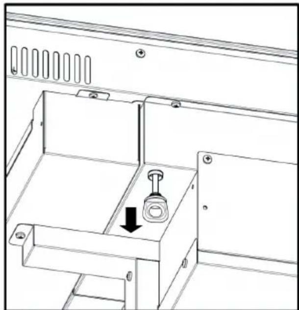
3) The liquid in the water tank can be emptied by pulling out the rubber plug as shown in Fig.10.
natural_image
Technical line drawing of a mechanical cabinet or enclosure with a central knob and directional arrow (no text or symbols)Fig.10
Note: Disassembly during use is strictly prohibited.
4) Suction port filter assembly disassembly and installation as shown in Figure 11, in order to remove the grid (1), grease filter (2), filter base/oil collector (3) activated charcoal filter (4).
Activated charcoal filter disassembly, firsthand to the opening of the handles, pull out flat, and then upward, they can be taken out, and cleaned. According to the disassembly of the reverse order, the filter can be loaded back into the air inlet of the product.
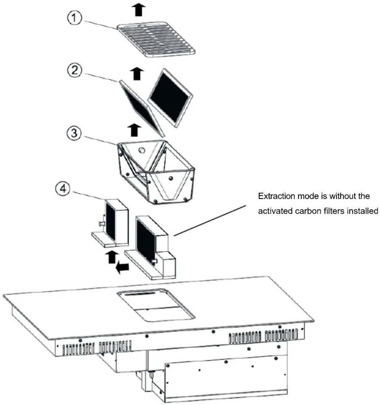
Fig 11
11. Trouble Shooting
| Error-Protection type | Error code display | |
| Timer display | Power level display | |
| Communication error with power version | F1 | |
| Induction hob NTC failure | F3 | |
| IGBT NTC failure F4 | ||
| Press for more than 10 seconds | ER03 | |
| Overheating of bobbin NTC E1 | ||
| IGBT overheating E2 | ||
| High-Voltage protection E3 | ||
| low-voltage protection | E4 | |
| Bobbin NTC Removal Protection E5 | ||
12. Customer Care Service
Before contacting Customer Care Service
1) Check that you cannot solve the problem yourself based on the points described in "Troubleshooting".
2) Switch the device off and on again to see if the problem resolves itself.
3) If the fault persists after the above checks, contact the nearest Customer Service.
| Country | Website |
| Denmark | www.eico.dk |
| Norway | www.eico-as.no |
| Sweden | www.eico.se |
| Finland | www.eico.fi |
| Germany, Spain, France,Netherlands (ENGLISH) | www.eico.eu |
INDHOLD
natural_image
Technical line drawing of a mechanical or electrical component with no visible text or symbolsnatural_image
Circular black-and-white illustration of a coiled or twisted object with no visible text or symbols1 stk. -
4 stk. beslag
natural_image
Illustration of various hand tools including gloves, screwdriver, flip plate, scissors, and a nail polish (no text or labels)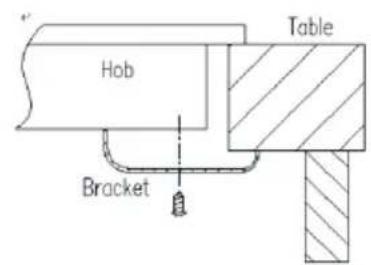
Det anbefales at produktet monteres af to personer, da dette er lettere.
natural_image
Two identical black silhouette figures of men standing side by side (no text or symbols)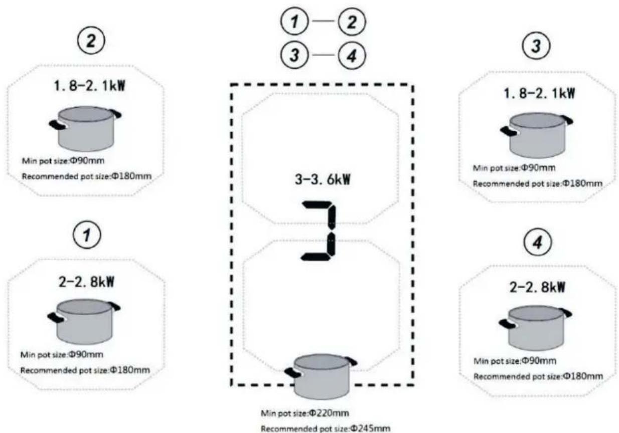
Fig 8

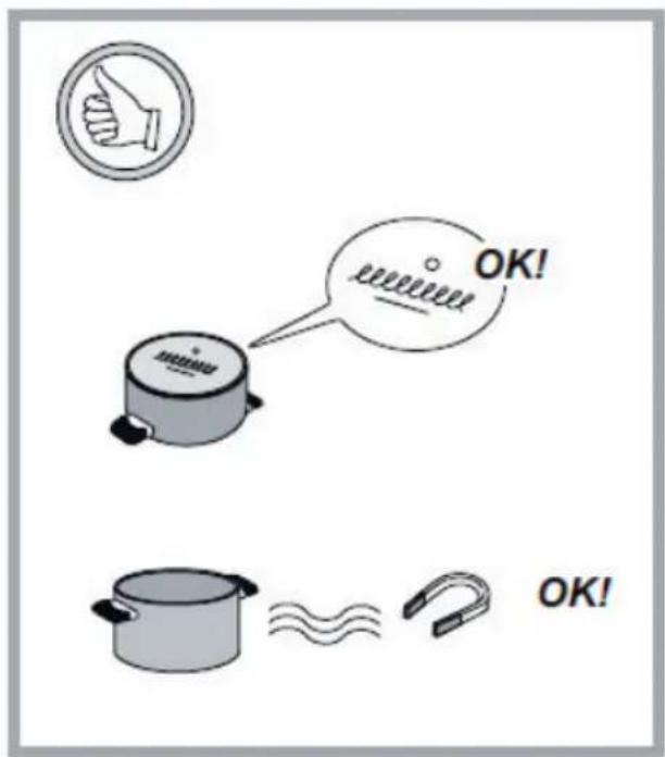
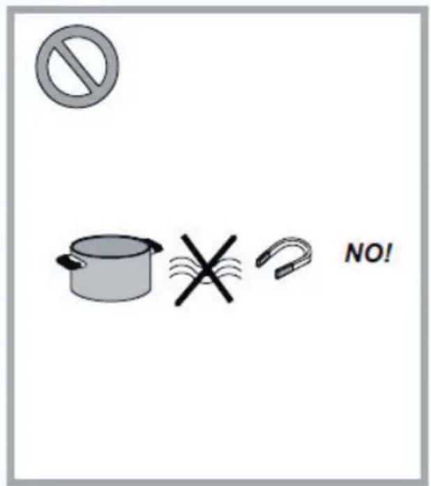
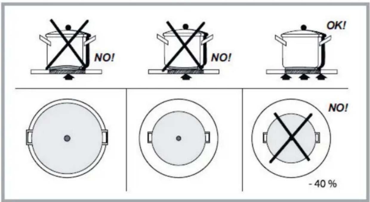
Fig. 9
natural_image
Technical line drawing of a mechanical assembly with a central component and directional arrow (no text or symbols)Fig. 10
natural_image
Technical line drawing of a mechanical or electrical component with no visible text or symbolsnatural_image
Illustration of various hand tools including gloves, screwdriver, screwdriver holder, pencil, eraser, and spray gun (no text or labels)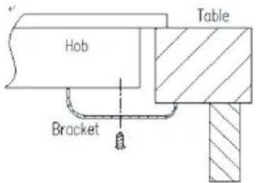
natural_image
Two identical black silhouette figures of men, no text or symbols present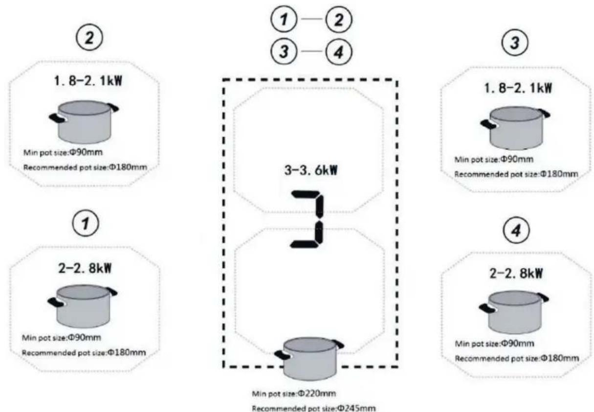
Fig 8

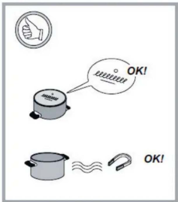
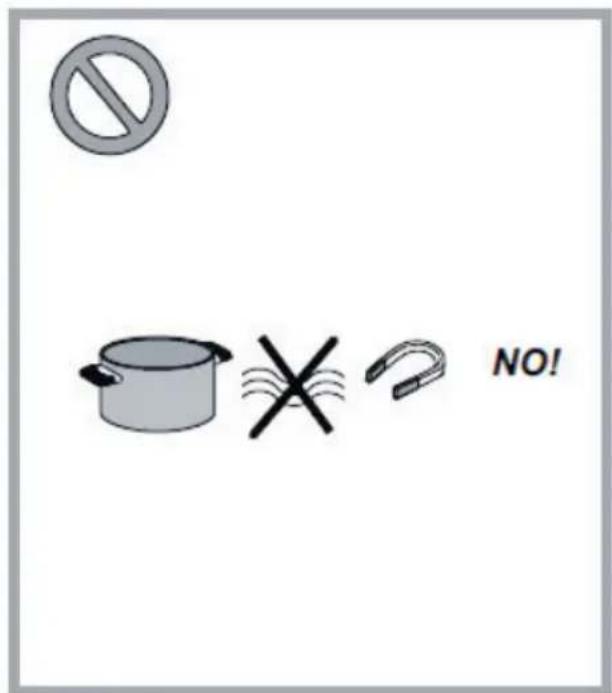
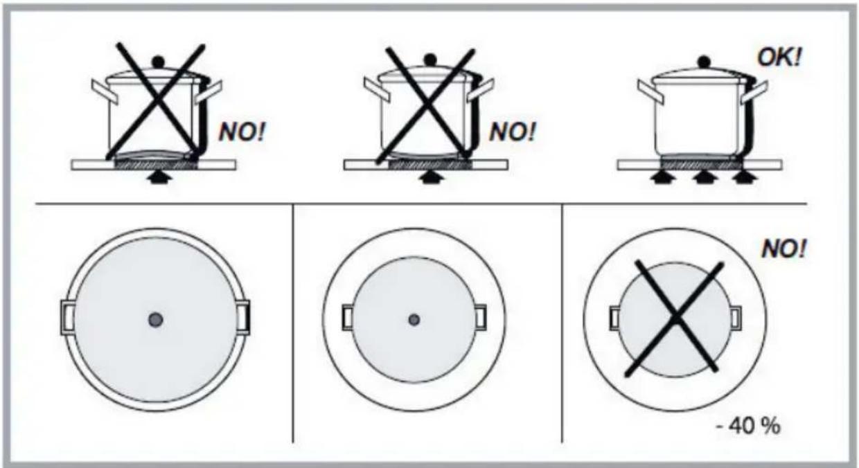
Fig.9
natural_image
Technical line drawing of a mechanical assembly with a central component and directional arrow (no text or symbols)Merknad: Demontering under bruk er strengt forbudt.
natural_image
Technical line drawing of a mechanical or electrical component with no visible text, numbers, or symbols.natural_image
Spiral black-and-white illustration of a coiled cable or wire (no text or symbols)1 st - tätningstejp
4 st fästen
natural_image
Illustration of various hand tools including gloves, screwdriver, pen holder, eraser, and soldering iron (no text or labels)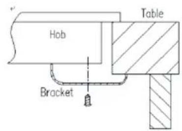
natural_image
Two identical black silhouette figures of men standing side by side (no text or symbols)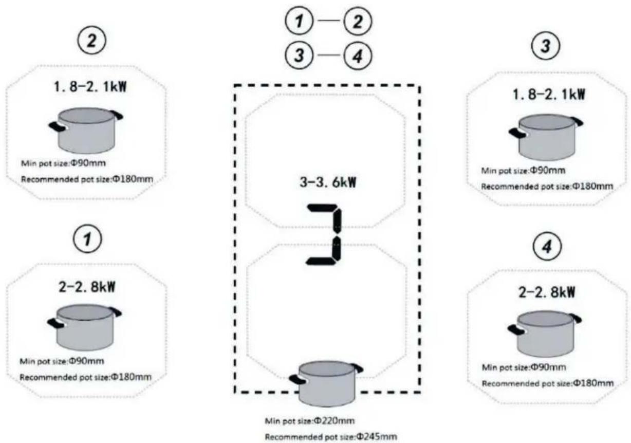
Fig 8

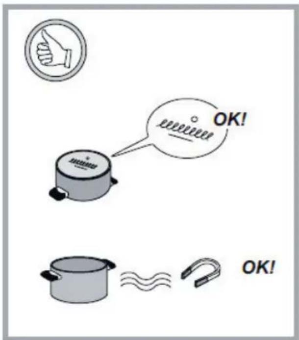
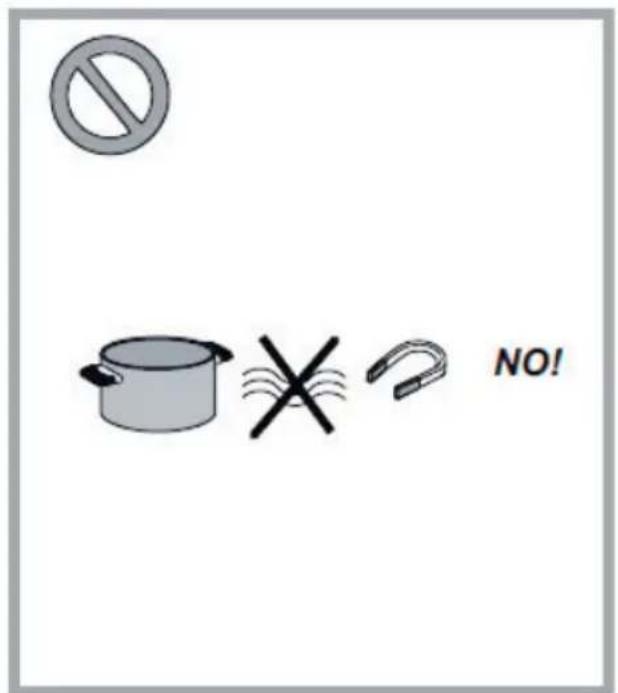
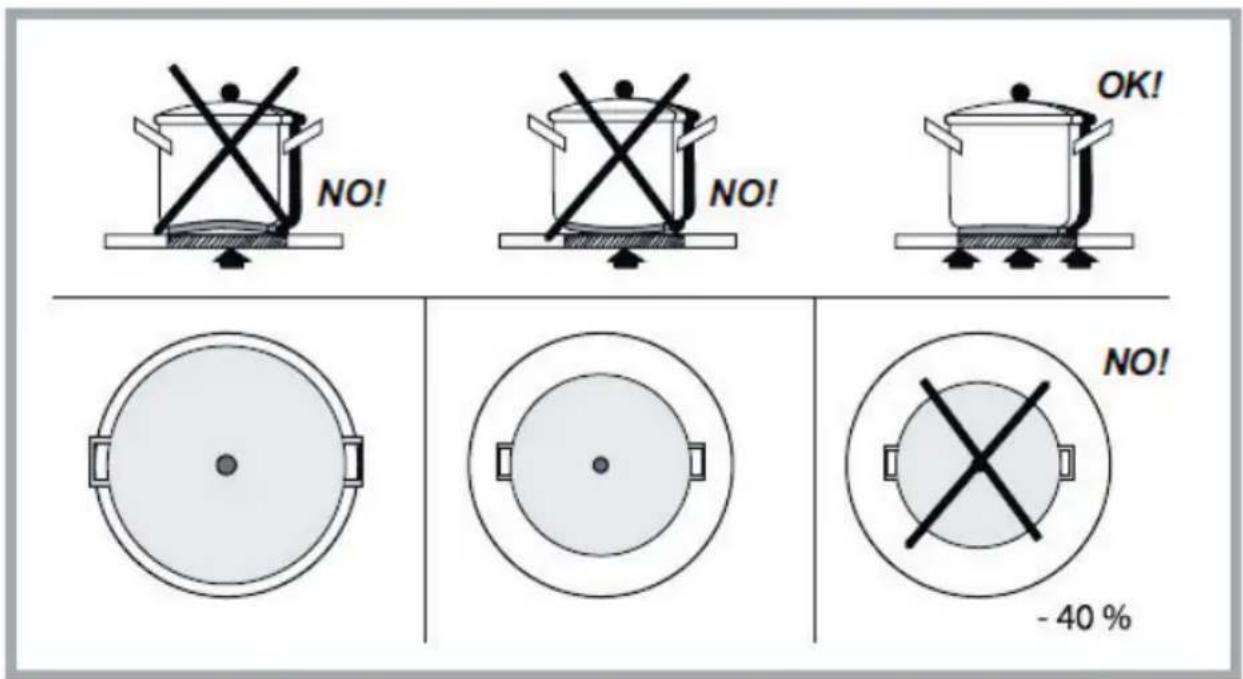
Fig.9
natural_image
Technical line drawing of a mechanical assembly with a valve and housing (no text or symbols)Fig.10
natural_image
Technical line drawing of a mechanical or electrical component with no visible text, numbers, or symbols.natural_image
Illustration of various hand tools including gloves, screwdriver, screwdriver holder, knife, and spray gun (no text or labels)natural_image
Two identical black silhouette figures of men standing side by side (no text or symbols)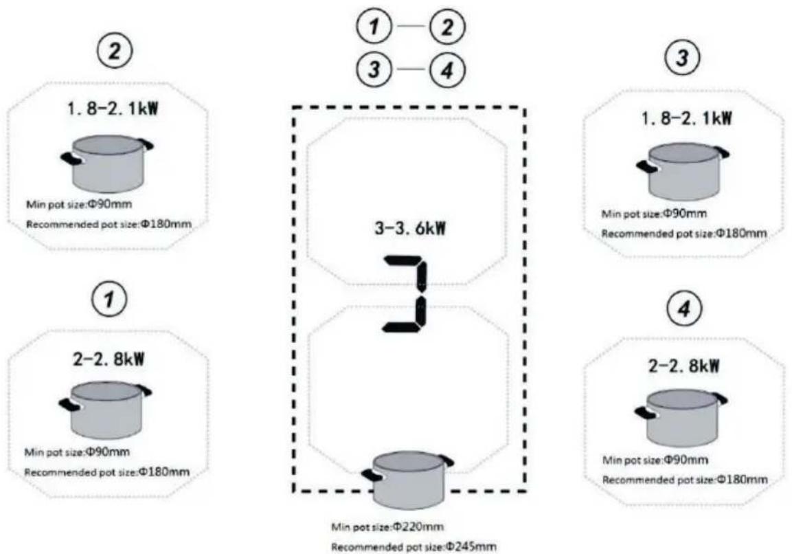
Kuva 8

Kuva 9
natural_image
Technical line drawing of a mechanical cabinet or enclosure with a central lock and mounting bracket (no text or symbols)Kuva 10
natural_image
Technical line drawing of a mechanical or electrical component with no visible text, numbers, or symbols.natural_image
Illustration of various hand tools including gloves, screwdriver, clip, pen, and spray can (no text or labels)natural_image
Two identical black silhouette figures of men, no text or symbols present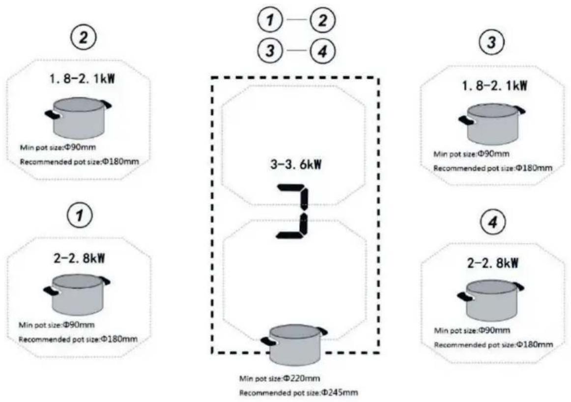
Abb.8

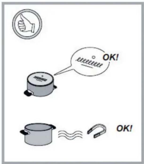
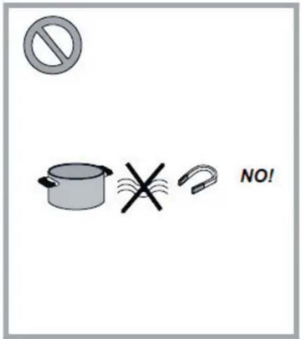
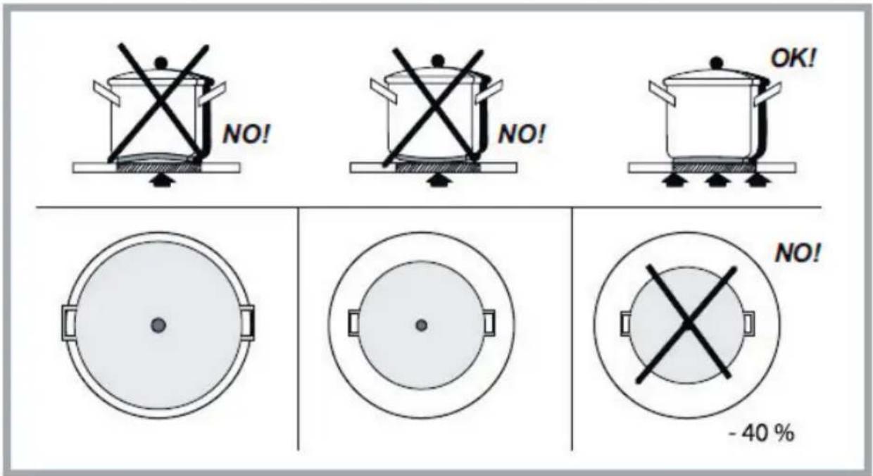
Abb. 9
natural_image
Technical line drawing of a mechanical assembly with a central component and mounting holes (no text or symbols)Abb. 10
natural_image
Technical line drawing of a mechanical or electrical component with no visible text or symbolsnatural_image
Circular black-and-white illustration of a coiled or twisted film strip (no text or symbols)1 cinta de sellado
4 soportes
natural_image
Illustration of various hand tools including gloves, screwdriver, clip, pen holder, scissors, and power tool (no text or labels)natural_image
Two identical black silhouette figures of men standing side by side (no text or symbols)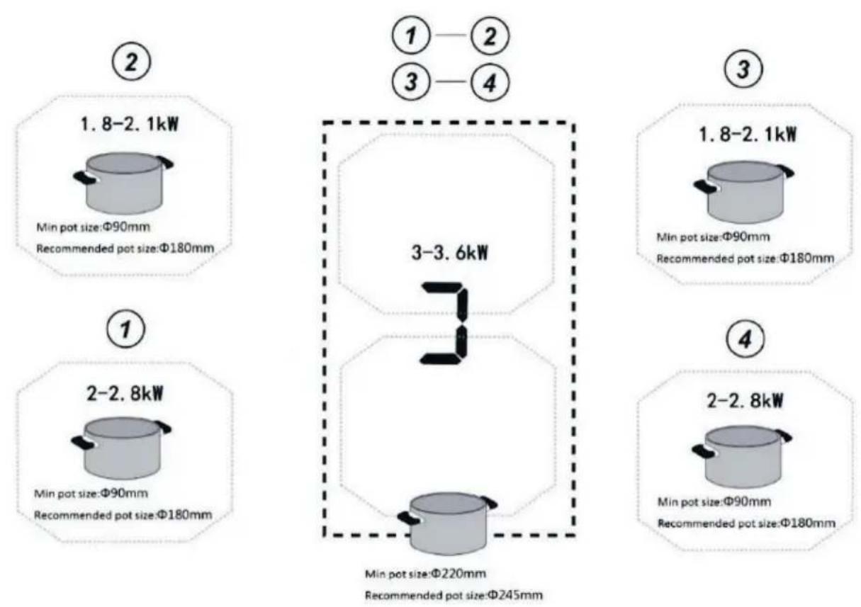
Fig 8

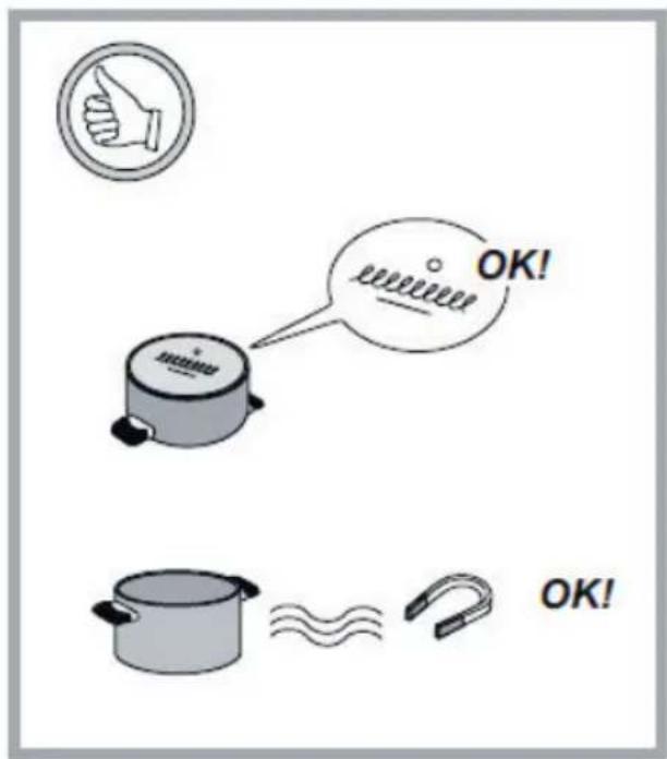
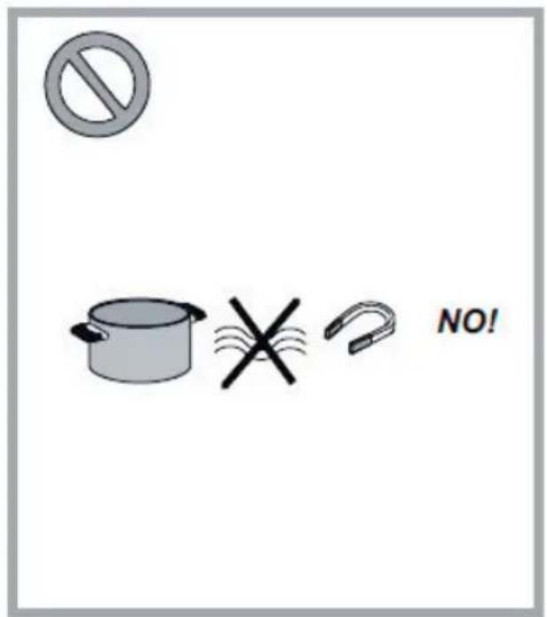
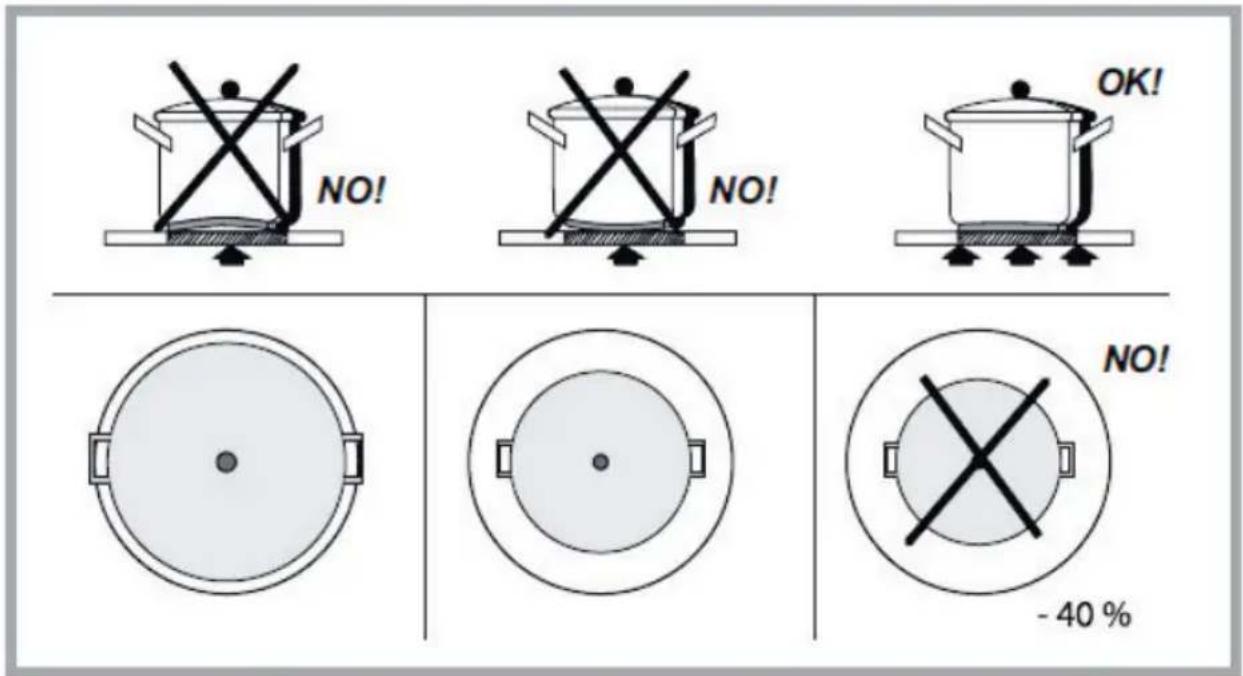
Fig. 9
natural_image
Technical line drawing of a mechanical assembly with a central component and directional arrow (no text or symbols)Fig.10
natural_image
Technical line drawing of a mechanical or electrical component with no visible text, numbers, or symbols.natural_image
Illustration of various hand tools including gloves, screwdriver, pushpin, screwdriver, and spray gun (no text or labels)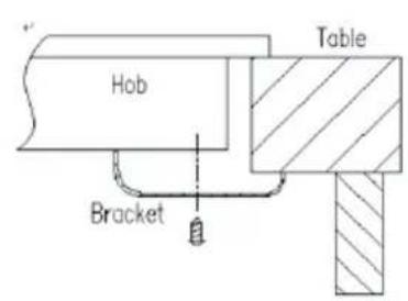
natural_image
Two identical black silhouette figures of men standing side by side (no text or symbols)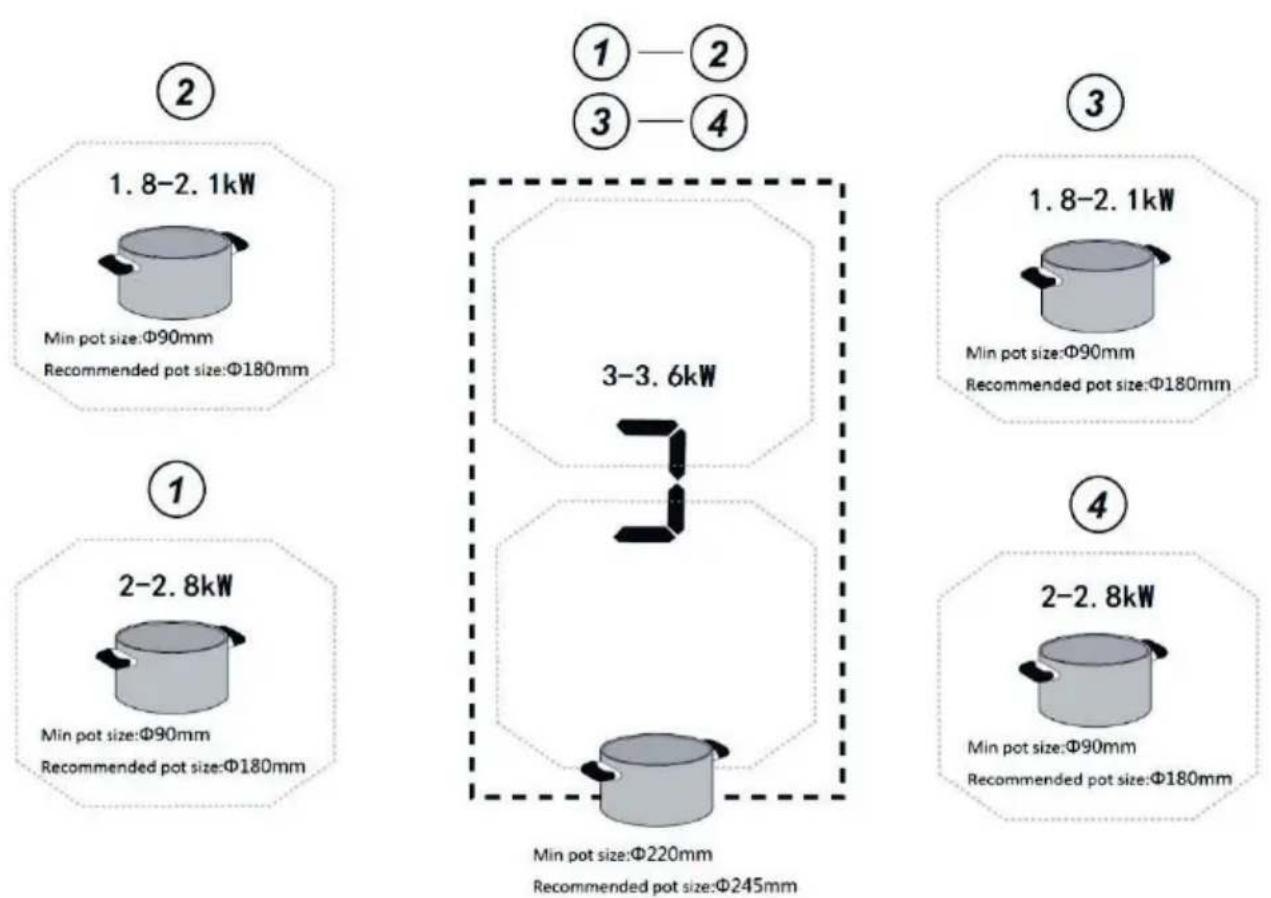
Fig 8

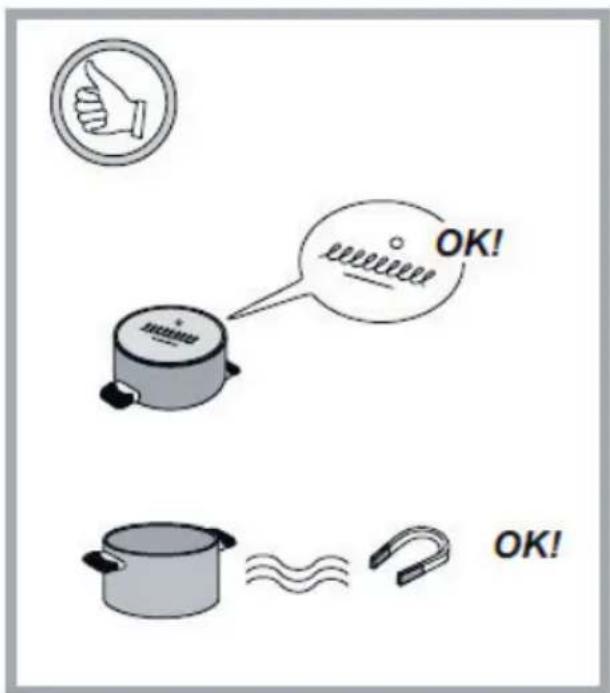
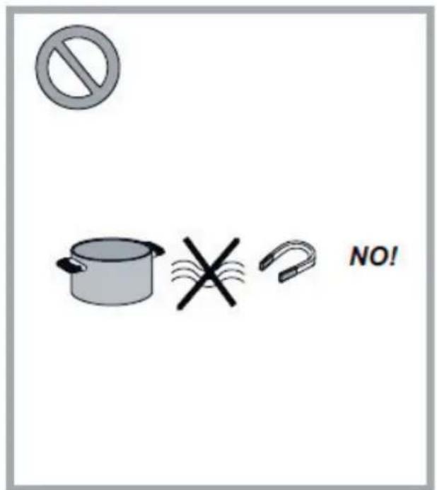
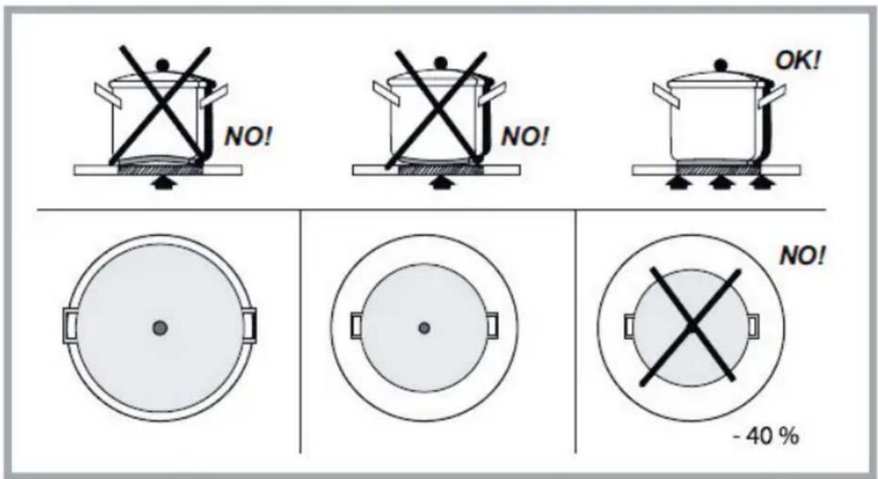
Fig. 9
natural_image
Technical line drawing of a mechanical assembly with a central knob and directional arrow (no text or symbols)Fig.10
natural_image
Technical line drawing of a mechanical or electrical component with no visible text, numbers, or symbols.natural_image
Illustration of various hand tools including gloves, screwdriver, flip plate, scissors, and a measuring tool (no text or labels)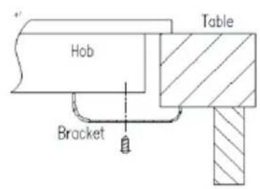
natural_image
Two identical black silhouette figures of men, no text or symbols present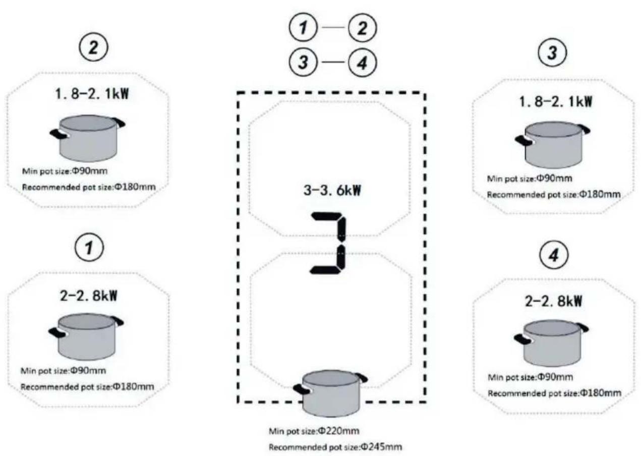
Fig 8


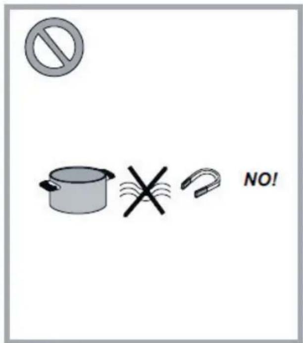
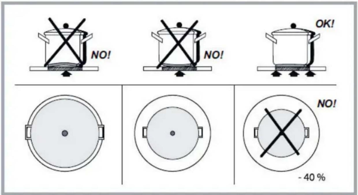
Fig.9
natural_image
Technical line drawing of a mechanical assembly with a central bolt and housing (no text or symbols)Fig.10


- CONTENTS
- Always Pay attention to
- Warnings
- Important:
- Regulations:
- Using the hob
- Advantages:
- Using of Pots:
- Pre-existing cookware:
- Recommended pan bottom diameters:
- Energy saving advice
- Included in the box
- Product Overall Dimension
- How to install the product
- Recommend Cooking Zone to be used for the pot
- How to use the control panel
- Care and Maintenance
- Trouble Shooting
- Customer Care Service
- INDHOLD
Brand : EICO
Model : Aero 80 N A
Category : Hob