
SMART1500PSGLCD - Uninterruptible power supply Tripp Lite - Free user manual and instructions
Find the device manual for free SMART1500PSGLCD Tripp Lite in PDF.

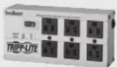
| Product type | Uninterruptible Power Supply (UPS) |
| Brand | Tripp Lite |
| Model | SMART1500PSGLCD |
| Rated power | 900 W / 1500 VA |
| Nominal input voltage | 120 V~ (range 97-145 V) |
| Input frequency | 50/60 Hz |
| Nominal output voltage | 120 V~ in line and battery mode |
| Output waveform | Pure sine wave |
| Transfer time | 6 ms typical, 10 ms maximum |
| Battery backup outlets | 5 outlets 5-15R (including 1 master outlet) |
| Surge-only outlets | 5 outlets 5-15R |
| USB charging ports | 1x USB-A + 1x USB-C (5 V, 3 A total) |
| Communication port | USB |
| Surge protection | Phone/Network (RJ11/RJ45) |
| Display | Removable color LCD |
| Full load runtime | 3 minutes |
| Recharge time | 7 hours |
| Battery type | Sealed lead-acid, maintenance-free |
| Energy-saving mode (ECO) | Yes, configurable |
| Automatic voltage regulation (AVR) | Yes, maintains 120 V ±10% for input 97-145 V |
| Cooling fan | Yes |
| Maximum operating altitude | 3,000 m |
| Safety | Input circuit breaker, automatic shutdown on overload |
| Maintenance | Recharge batteries every 3 months in storage; battery replacement by qualified personnel |
| Spare parts and repairability | Replacement batteries (model BP24V9T for external battery); no user-serviceable parts except batteries |
Frequently Asked Questions - SMART1500PSGLCD Tripp Lite
User questions about SMART1500PSGLCD Tripp Lite
0 question about this device. Answer the ones you know or ask your own.
Ask a new question about this device
Download the instructions for your Uninterruptible power supply in PDF format for free! Find your manual SMART1500PSGLCD - Tripp Lite and take your electronic device back in hand. On this page are published all the documents necessary for the use of your device. SMART1500PSGLCD by Tripp Lite.
USER MANUAL SMART1500PSGLCD Tripp Lite
(Series Numbers: AG-0529, AG-052A, AG-052B, AG-052C)
Not suitable for mobile applications.
- Important Safety Instructions 2
- Introductions 4
- Package Contents 4
- Product Overview
- Installation 6
- Battery Replacement 8
-
ECO Energy-Saving Setup 10
-
Operation 10
- Troubleshooting 20
- Specifications 21
- Storage and Service 22
- Product Registration 22
- Regulatory Compliance 23
Español 24 • Français 47
To download the LED control Software, please visit tripplite.com/support or scan this QR code.

WARRANTY REGISTRATION
Register your product today and be automatically entered to win an ISOBAR ^® surge protector in our monthly drawing!
tripplite.com/warranty


Manufacturing Excellence.
1111 W. 35th Street, Chicago, IL 60609 USA • tripplite.com/support
Copyright © 2021 Tripp Lite. All rights reserved.
1. Important Safety Instructions
SAVE THESE INSTRUCTIONS
This manual contains instructions and warnings that should be followed during the installation, operation and storage of this product. Do not operate the UPS before reading all safety information and operating instructions thoroughly. Comply with all warnings and operating instructions. Failure to heed these warnings may affect the warranty.
Transportation
- Transport the UPS system only in the original package to protect against shock and impact.
Preparation
- Do not dismantle the UPS system. There are no user-serviceable parts.
- Do not plug the UPS input into its own output.
- Do not attach a power strip or surge suppressor to the UPS.
- Do not attach non-computer-related items, such as medical equipment, life-support equipment, microwave ovens or vacuum cleaners to UPS.
- Condensation may occur if the UPS system is moved directly from a cold environment to a warm environment. The UPS system must be completely dry before installation. Allow at least two hours for the UPS system to acclimate to the environment.
- Do not install the UPS system near water or in a moist environment.
- Do not install the UPS system where it will be exposed to direct sunlight or heat.
- Do not block the ventilation openings in the UPS housing.
Installation
- This UPS intended for installation in a controlled environment (temperature-controlled, indoors and free of conductive contaminants). Avoid installing the UPS in locations where there is standing or running water or excessive humidity.
- Do not mount unit with its front or rear panel facing down (at any angle). Mounting in this manner will seriously inhibit the unit's internal cooling, eventually causing product damage not covered under warranty.
- Caution - Changes or modifications not expressly approved by the party responsible for compliance could void the user's authority to operate the equipment.
Operation
- Keep fluids and other foreign objects away from the interior of the UPS system.
- Do not connect appliances or devices which would overload the UPS system to the UPS outlets.
- Place cables in such a way that no one can step on or trip over them.
- Do not connect household appliances, such as hair dryers, to UPS output sockets.
- The UPS system can be operated by individuals with no previous experience.
- Connect the UPS system only to a properly grounded AC power outlet that is easily accessible and close to the UPS system.
- Use only a VDE-tested, UL-marked power cable (e.g. the power cable of your computer) to connect the UPS system to the building wiring outlet (grounded outlet).
1. Important Safety Instructions
Maintenance, Service and Faults
- The UPS system operates with hazardous voltages. Repairs may be carried out only by qualified service personnel.
- Caution - risk of electric shock. Even after the unit is disconnected from the mains (building wiring outlet), components inside the UPS system are still connected to the battery and electrically live and dangerous.
- Before performing any kind of service and/or maintenance, disconnect the batteries and verify that no current is present and no hazardous voltage exists in the terminals of high-capability capacitors such as bus-capacitors.
Battery Warnings
- Batteries can present a risk of electrical shock and burn from high short-circuit current. Observe proper precautions. There are no user-serviceable parts inside the UPS. Do not open the UPS except to perform battery replacement. Do not open batteries. Do not short or bridge the battery terminals with any object. Do not dispose of batteries in a fire. The batteries may explode. Released material is harmful to the skin and eyes. It may be toxic. Unplug and turn off the UPS before performing battery replacement. Use tools with insulated handles. Battery replacement should be performed only by authorized service personnel using the same number and type of batteries (Sealed Lead-Acid). Do not dispose of the batteries in a fire. Visit Tripp Lite at triplite.com/products/battery-finder to locate the specific replacement battery for your UPS.
Storage and Maintenance
Before storing, charge the UPS 5 hours. Store the UPS covered and upright in a cool, dry location. During storage, recharge the battery in accordance with the following table:
| Storage Temperature Recharge | Frequency Charging Duration | |
| 32°F to 104°F / 0°C to 40°C Every 8 months 1-2 hours | ||

Pb

[NO TEXT]
The batteries are recyclable. Refer to your local codes for disposal requirements or in the USA only call 1-800-SAV-LEAD or 1-800-8-BATTERY (1-800-822-8837) or visit tripplite.com/support/recycling-program/ for recycling information.
2. Introduction
This product is an intelligent line-interactive sine wave UPS, designed to protect your personal computer or sensitive electronic equipment from all forms of power interference, including complete power failure.
3. Package Contents
- UPS Unit
- USB Cable
- Owner's Manual
Note: Before installation, please inspect the unit. Be sure that nothing inside the package is damaged. Keep the original package in a safe place for future use.
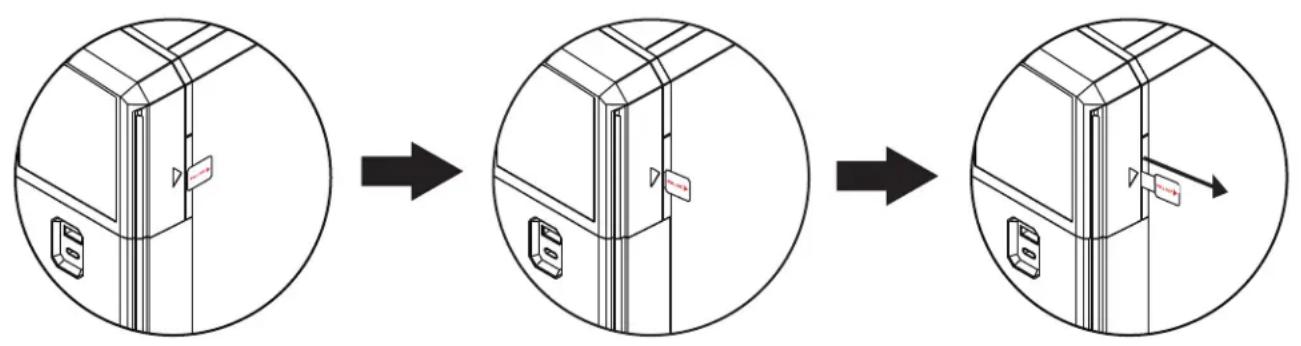
BEFORE USING THE UPS BE SURE TO REMOVE THE LABEL FROM REMOTE LCD PANEL
flowchart
graph LR
    A["Opening Door"] --> B["Disassembly"]
    B --> C["Final Disassembly"]
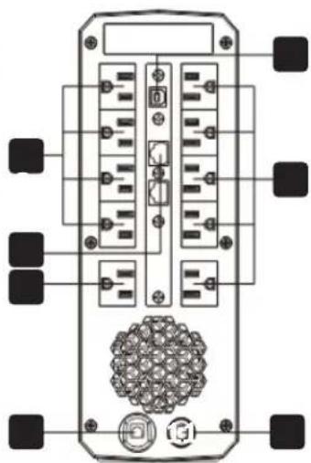
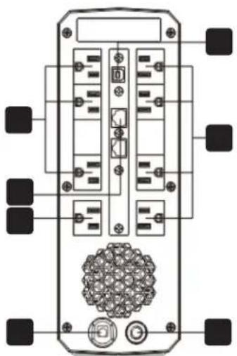
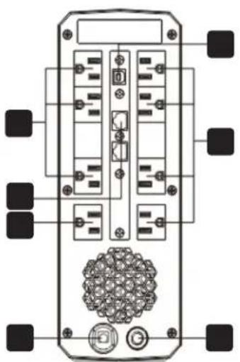
4. Product Overview
SMART1500PSGLCD
natural_image
Top-down schematic of a device rear panel with ports and connectors (no text or labels)SMART1200PSGLCD
natural_image
Top-down schematic of a device rear panel with ports and connectors (no text or labels)SMART1000PSGLCD SMART600PSGLCD
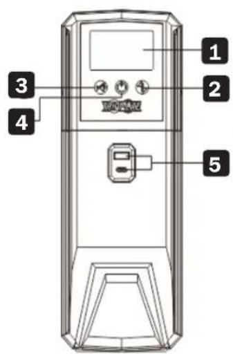
SMART1500PSGLCD (without battery connection cover)
1 LCD Display
2 Up / Down Button
3 Mute Button
4 On / Off Button
5 USB Charger Ports for Device Charging (5V 3A, 1x USB-A, 1x USB-C)
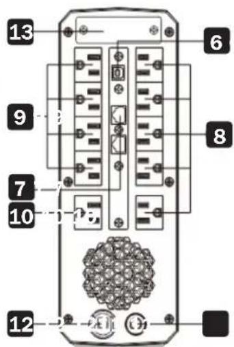
6 USB Communication Port for UPS Monitoring and Control
7 Modem/Phone/Network Surge Protection
8 Surge-Protected Outlets
9 Battery Backup Outlets
10 Master Battery Backup and Surge-Protected Outlet
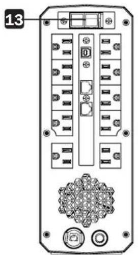
11 Input Circuit Breaker
1.2 Input Power Cord for Connecting to Utility Power
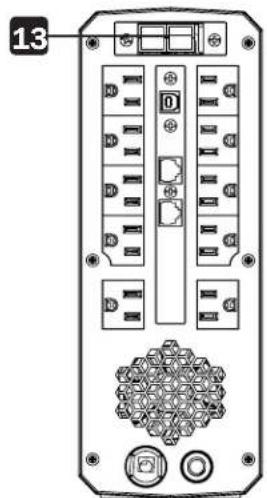
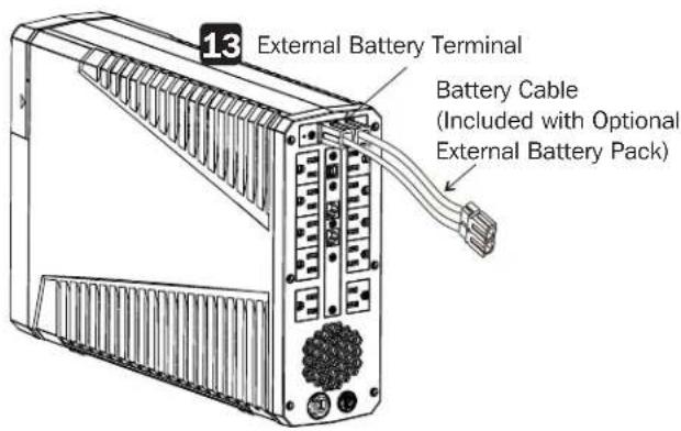
13 External Battery Terminal (Model SMART1500PSGLCD)
5. Installation
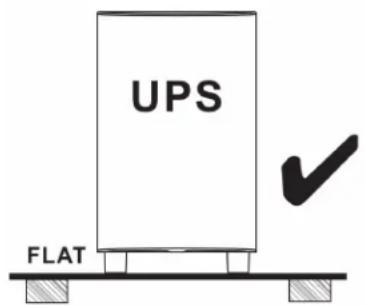
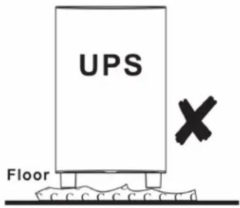
Before installing the UPS, select a proper location to install the UPS.
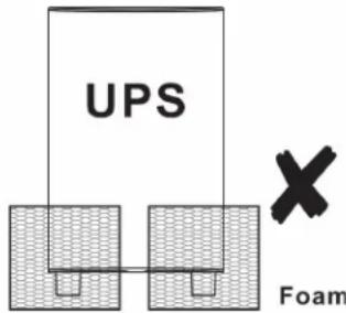
- Place the UPS on a flat and clean surface, away from vibration, dust, humidity, high temperature, flammable liquids and gases and corrosive and conductive contaminants. Install the UPS indoors in a clean environment, away from windows and doors.

- Use the UPS at a maximum altitude of 3281 ft. (1000 m) to keep UPS normal operation at full load. In high-altitude areas, reduce the connected load. Altitude derating power with connected loads for normal operation is listed as below:
| Altitude Derating factor | 1 |
| 3281 ft. (1,000 m) | 1.0 |
| 4921 ft. (1,500 m) | 0.95 |
| 6562 ft. (2,000 m) | 0.91 |
| 8202 ft. (2,500 m) | 0.86 |
| 9843 ft. (3,000 m) | 0.82 |
| 11,483 ft. (3,500 m) | 0.78 |
| 13,123 ft. (4,000 m) | 0.74 |
| 14,764 ft. (4,500 m) | 0.7 |
| 16,404 ft. (5,000 m) | 0.67 |
Based on density of dry air = 1.225 kg/m3 at sea-level, +15°C
^1 Because fans lose efficiency with altitude, force air-cooled equipment will have a smaller derating.
The UPS is equipped with a fan for cooling. Place the UPS in a well-ventilated area. Maintain minimum clearance of 4 in. (100 mm) in front of the UPS and 12 in. (300 mm) in the back and on the sides of the UPS for heat dissipation and maintenance.
5. Installation
Quick Start Guide
This quick-start guide describes the power-up procedure of the UPS in the factory-default configuration.
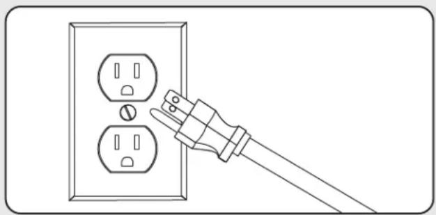
Step 1: Plug the UPS into a 120V AC Power Source
Plug the UPS into a two-pole, three-wire, grounded receptacle only. Do not use an extension cord. Charge the battery at least 5 hours before initial use. The unit charges its battery while connected to utility power even when UPS output is turned off.
natural_image
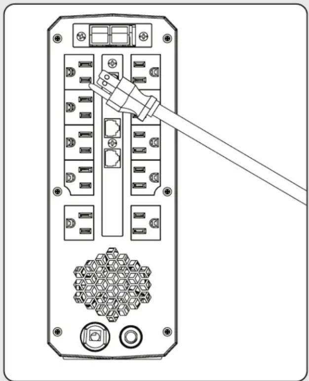
Line drawing of a hand inserting a plug into an electrical outlet (no text or symbols)Step 2: Plug Equipment into the UPS
There are two types of outlets on the back of the UPS:
SURGE ONLY Outlets – These outlets do not provide battery backup power during power outages. Connect items like printers, desk lamps and other devices not requiring battery backup support to these outlets.
UPS & SURGE Outlets – This bank of outlets offer UPS battery backup support during power failures. Connect vital computer system components that require UPS support to these outlets.
There are two types of UPS & SURGE outlets:
Single-Designated MASTER + UPS & SURGE Outlet – This is the ideal location to connect your COMPUTER power cord for individual power consumption metering. This outlet can also be configured optionally to enable ECO-mode power saving (see section 7. ECO Energy-Saving Setup for more information).
CONTROLLED BY MASTER + UPS & SURGE Outlets -
This bank of UPS supported outlets can be optionally configured to automatically power off and on again in response to power consumption level on the MASTER outlet (see section 7. ECO Energy-Saving Setup for more information).
natural_image
Diagram of a server rack with connected ports and a cable, showing no text or symbolsOptional Installation:
- USB cable
• Tel/Ethernet surge protection
Note: These connections are optional. The UPS will work properly without these connections.
5. Installation
Remote panel operation
The LCD panel can be removed from the base and placed in a location that is easier to view. Follow the steps below to remove the remote panel. The distance between the remote panel and the base cannot exceed 20 ft. (6 m).
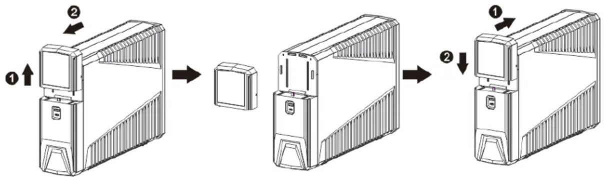
flowchart
graph TD
    A["1: Display unit"] --> B["2: Insert/Down"]
    B --> C["3: Box with lid"]
    C --> D["4: Assembly unit with top panel"]
    D --> E["5: Down/Up/Left panel"]
An NiMH battery is installed on the back of remote panel. Once the remote panel is installed on the base unit, it charges the battery automatically. When the battery capacity is low, the ☐ icon flashes to remind you to charge the remote panel.
6. Battery Replacement
Under normal conditions, the original battery in your UPS will last several years. Battery replacement should only be performed by qualified service personnel. Refer to Battery Warnings in section 1. Important Safety Instructions for complete safety information.
- WARNING! This UPS contains potentially hazardous voltages. Do not attempt to disassemble the UPS beyond the battery replacement procedure.
- This UPS contains no user serviceable parts. Repairs and battery replacement must be performed by QUALIFIED SERVICE PERSONNEL ONLY.
- Caution - Do not dispose of batteries in a fire. The batteries may explode.
- Caution - Do not open or mutilate batteries. Released electrolyte is harmful to the skin and eyes. It may be toxic.
-
Caution - A battery can present a risk of electrical shock and high short-circuit current. Contact with any part of a grounded battery can result in electrical shock. The following precautions should be observed when working on batteries:
-
Remove watches, rings or other metal objects.
- Use tools with insulated handles.
- Wear rubber gloves and boots.
- Do not lay tools or metal parts on top of batteries.
- Disconnect the charging source and load prior to installing or maintaining the battery.
-
Remove battery grounds during installation and maintenance to reduce the likelihood of shock. Remove the connection from ground if any part of the battery is determined to be grounded.
-
Caution - risk of electric shock. The battery circuit is not isolated from the input voltage. Hazardous voltages may occur between the battery terminals and the ground. Before touching, verify that no voltage is present.
- Replace the fuse or circuit breaker only with the same type and amperage in order to avoid fire hazards.
- Only persons adequately familiar with batteries and the required precautionary measures may replace batteries and supervise operations. Unauthorized persons must keep away from the batteries.
- Caution - Replace batteries with the same number and type as originally installed in the UPS. These batteries have pressure-operated vents. The UPS system contains sealed, non-spillable maintenance-free lead acid batteries.
6. Battery Replacement
Note: If there is a power interruption while replacing the batteries, the load will not be backed up even if the UPS is on. To replace the batteries with UPS on, start with step 5.
Follow the steps below to replace the battery.
Step 1: Turn off all equipment plugged into the UPS system's outlets.
Step 2: Turn off the UPS.
Step 3: Remove the UPS system's AC input plug from the AC wall outlet.
Step 4: Unplug all equipment from the UPS system's outlets.
Step 5: Remove the battery cover by loosening the two screws A located on the bottom of the UPS and slide the battery cover downward, then outward.
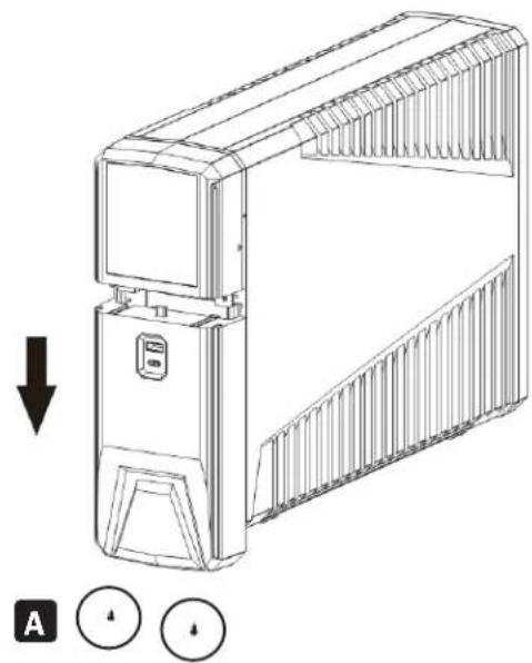
natural_image
Technical line drawing of a mechanical device with a downward arrow and two circular indicators below (no text or symbols)Step 6: Disconnect the battery wires B (BAT+ and BAT-).
Then, slide out the existing battery pack from the UPS by grasping the battery tap.
Caution - Do NOT short the positive wire and negative wire of the battery.
Caution - DO NOT pull the battery pack out by pulling on the battery wires.
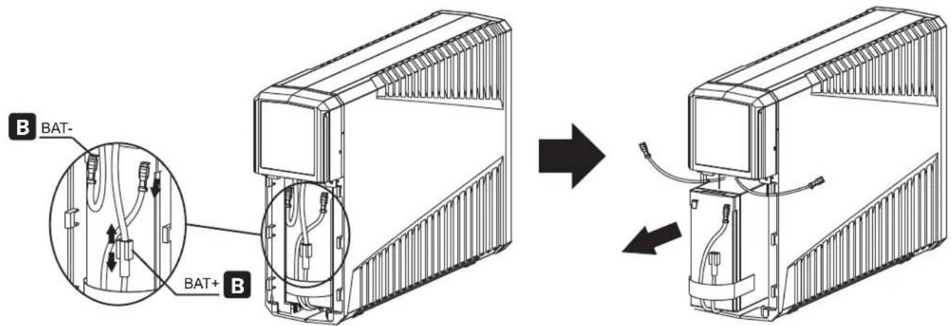
Step 7: Slide the new battery pack into the UPS.
Step 8: Verify proper polarity. Reconnect the battery connectors.
Note: Some sparking might occur. This is normal.
Step 9: Reinstall the battery cover. The UPS is ready for normal operation.
Note: Properly dispose of the old batteries at an appropriate recycling facility. Refer to your local codes for disposal requirements or in the USA only call 1-800-SAV-LEAD or 1-800-8-BATTERY (1-800-822-8837) or visit tripplite.com/support/recycling-program/ for recycling information.
7. ECO Energy-Saving Setup
The ECO energy-saving feature enables your UPS system to save energy by automatically turning off designated outlets when your computer is turned off or in Standby Mode. ECO Mode is disabled by default.
Enabling ECO Mode
- Connect essential peripheral devices to the "Controlled by Master Outlet" outlets on the "Battery & Surge Only" side for battery and surge protection, with the option of being controlled by the Master Outlet.
- Connect a master device, such as a desktop computer or audio/visual receiver to the master outlet.
Note: A minimum of 20W is required for the master outlet to power on. - With the UPS system turned on and operating normally from utility power, press and hold the Up/Down button for 2 seconds to enter the LCD menu. Navigate to P13 to enable or disable ECO Mode.
- When the UPS system detects a drop in load (<20W) on the master outlet for approximately 3 minutes, it will turn off the "Controlled by Master Outlet" outlets. The 3-minute delay ensures the ECO outlets remain powered during a reboot.
8. Operation
LCD Panel and Front Panel Buttons


During normal AC and Battery mode operation, the UPS front-panel LCD screen will not be illuminated. To turn on the LCD backlight, press and release the front panel POWER button (release within 0.5 seconds or less to turn on the LCD backlight only).
Note: When turning on the UPS backlight only, be careful to press and release the POWER button quickly. Pressing and holding the power switch for 2 seconds will immediately power off the UPS.
8. Operation
Button Functions
| Button Function | |
| On/Off • Press and hold 2 seconds to turn the UPS on or off.Holding the “On/Off” button for 10 seconds can reset the unit in the event of communication failure between remote panel and UPS.Quick-press the button 5 times to reset pairing when wireless transmission fails.In Menu Mode, the On/Off button is used to select a sub-menu or approve the selection of a setting. | |
| Mute • Press and hold 2 seconds to enable or disable mute function.A quick press of the mute button will return to the main screen or exit the setting programs. | |
| Up/Down • Press and hold 2 seconds to enter the setting menu.A quick press will switch display information. |
Audible Alarms
| Overload Sounds every 0.5 seconds. | |
| Low Battery Sounds every second. | |
| Overcharge Sounds every 1.5 seconds. | |
| Battery Replacement Sounds every 2 seconds. | |
| Battery Mode Sounds every 10 seconds. | |
| Fault Sounds continuously. |
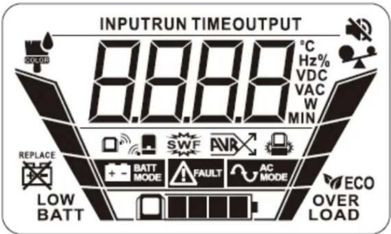
LCD Panel
| Operating Mode Display Icons | ||
| AC MODE |  | The AC MODE icon indicates the UPS is:RECEIVING acceptable AC utility input voltage.PROVIDING conditioned UPS output to connected equipment.READY to switch to battery mode in the case of power failure.CHARGING internal batteries as necessary to maintain full battery charge. |
| BATTERY MODE |  | The BATTERY MODE icon indicates the UPS is:RUNNING IN BATTERY BACKUP MODE and providing inverter-derived AC sine wave output to connected equipment using battery reserves.NOT RECEIVING acceptable AC utility input voltage. |
| Additional UPS Status Icons | ||
| UPS FAULT + Error Code |   | The UPS FAULT icon indicates the UPS is experiencing the fault condition indicated by the on-screen ERROR CODE.Some faults may cause UPS shutdown, depending on the severity of the fault condition encountered. A list of reported fault-codes are shown in section 9.Troubleshooting of this manual. |
| ALARM MUTE / DISABLE |  | The ALARM MUTE icon indicates the UPS alarm has been silenced during Battery mode operation.To set the ALARM MUTE function, press and hold the alarm-cancel button for approximately 2 seconds as the alarm is sounding. |
8. Operation
| Additional UPS Status Icons | ||
| ECO MODE |   | When the UPS system detects a drop in load (<20W) on the master outlet for approximately 3 minutes, it will turn off the “Controlled by Master Outlet” outlets.The 3-minute delay ensures the ECO outlets remain powered during a reboot. |
| LOAD LEVEL / OVERLOAD |  | The LOAD LEVEL / OVERLOAD METER continuously reports UPS output load level during AC and Battery Modes.The meter reports 1-bar (0-24%), 2-bars (25-49%), 3-bars (50-74%), 4-bars (75-100%) and OVERLOAD conditions (4-BARS + “OVERLOAD” logo and caption). |
| BATTERY CHARGE LEVEL |  | The BATTERY CHARGE LEVEL METER continuously reports condition of the sealed lead acid battery system during AC and Battery modes.The meter reports 1-bar (0-24%), 2-bars (25-49%), 3-bars (50-74%), 4-bars (75-100%) and LOW BATTERY conditions (1-BAR + “LOW BATT” caption). |
| AVR / AUTO-VOLTAGE REGULATION |  | The AVR icon indicates the UPS is actively correcting low or high utility voltage during AC Mode operation.The UPS is capable of maintaining 120V +/-10% output to connected equipment during undervoltages to 97V and overvoltages as high as 145V. Battery backup mode and battery charging capability are both available when AVR is engaged. |
| REPLACE BATTERY / BATTERY DISCONNECTED |  | The REPLACE BATTERY icon indicates the UPS battery system either requires replacement or is disconnected.The alarm will also sound every 2 seconds. |
| SITE WIRING FAULT |  | The SITE WIRING FAULT indicator indicates electrical wiring problems.Have electrical wiring inspected for fault conditions by a qualified electrician. |
| COLOR ICON |  | The COLOR ICON will display at various points during the configuration of LED bar color options.See the LED Color Bar Setting P9-P12 section for more information of this configuration-mode icon. |
| Display Module Status Icons | ||
| DISPLAY MODULE WIRELESS CONNECTION PAIRED |  | The WIRELESS CONNECTION PAIRED icon displays as the removable LCD Module is connected to the UPS via wireless connection. |
| DISPLAY MODULE DOCKED |  | The DISPLAY MODULE DOCKED icon displays as the LCD Module is reconnected to the UPS and a wired connection is made. |
| DISPLAY MODULE BATTERY CHARGE LEVEL |  | The DISPLAY MODULE BATTERY METER icon continuously reports battery charge level for the miniature NiMH battery that powers the removeable LCD Module.The meter reports 1-bar (low), 2-bars (medium), 3-bars (high) and 4-bars (full) charge level. This display flashes every 0.5 seconds to indicate Abnormal display module charging. |
Note: Except when in UPS fault condition, the LCD backlight automatically shuts off if there is no action for 1 minute (30 seconds when panel is removed from base).
8. Operation
LCD Data Reporting Screens
The UPS allows you to scroll through a set of 14 information screens of measurement values regarding the UPS, Utility Power and firmware version information. To scroll through the available set of screens, press the UP/DOWN button repeatedly.
| No. | Selectable Information LCD | Screen Additional Information | |
| 1 | Input Voltage Values indicate the AC input voltage the UPS is  | receiving through the input power cord. | |
| 2 | Input Frequency Values indicate the AC input frequency (Hz) 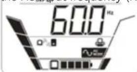 | the UPS is receiving through the input power cord. | |
| 3 | Battery Voltage Values indicate the DC voltage of the main lead-acid battery system powering the UPS output during power failures. 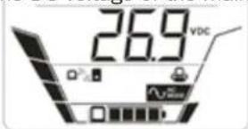 | ||
| 4 | Battery Capacity Values indicate the charge percentage of the main lead-acid battery system that powers the UPS output during power failures. 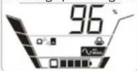 | ||
| 5 | Estimated Backup Time Values indicate the estimated battery runtime the UPS provides during a power failure at the current load and battery-charge levels. 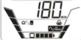 | ||
| 6 | Output Voltage Values indicate the AC output voltage provided to connected equipment via UPS output receptacles. 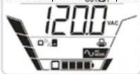 | ||
| 7 | Output Frequency Values indicate the AC output frequency (Hz) provided to connected equipment via UPS output receptacles. 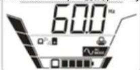 | ||
8. Operation
| No. | Selectable Information LCD | Screen Additional Information | |
| 8 | Output in Watts Values indicate | the UPS output load wattage 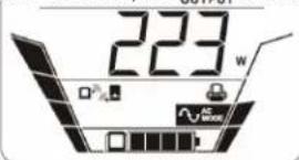 | of equipment connected to all Battery Backup Outlets combined (includes the Master Battery Backup and Surge-Protected Outlet). |
| 9 | Output Load % Values indicate | the UPS output load percentage 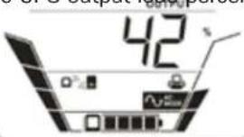 | consumed by equipment connected to all Battery Backup Outlets combined. |
| 10 | Master Outlet Power Consumption | 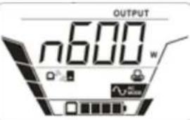 | Values indicate the Master outlet load wattage reports power consumption for the single device connected to the master outlet (the Master outlet is most commonly used to power your CPU device). |
| 11 | Detachable LCD Module Battery Voltage | 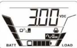 | Values indicate the voltage of the miniature internal NiMH battery that powers the LCD Panel when it is removed from the UPS (full-charge is approximately 3.0V DC). |
| 12 | Panel Board Firmware Version | 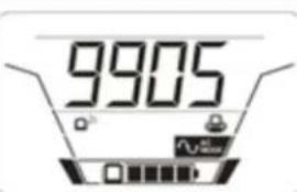 | Indicates the firmware version. |
| 13 | Base Board Firmware Version | 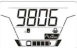 | Indicates the firmware version. |
| 14 | UPS Control Board Firmware Version | 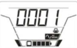 | Indicates the firmware version. |
8. Operation
UPS Set-Up & LED Programming Mode
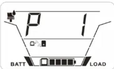
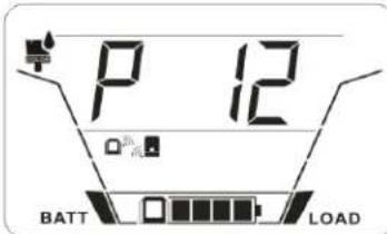
UPS Set-Up / Programming mode contains 13 screens of user-selectable UPS and LED programming options. Each of the programming options are designated on-screen as items P1 through P13 (SMART1500PSGLCD offers a P14 option).
To enter UPS Set-up mode:
- Press and hold the UP/DOWN button for two seconds.
- The UPS will enter Set-up mode and display program P1 on the LCD screen.
- Press the UP/DOWN button repeatedly advance to other program options (P1, P2, P3, etc.).
To edit individual programming options:
- Advance the screen to the program to be edited (P1, P2, P3, etc.).
- Press the POWER button to ENTER SELECTABLE OPTIONS.
- Press the POWER button again to VIEW SELECTION OPTIONS (the first selectable option will flash).
- Press the UP/DOWN button repeatedly to scroll through available selection options (the option selected will be flashing).
- Once the desired selectable option is flashing, press the POWER button again to SELECT it (the selected option will stop flashing and the program will immediately go into effect).
LED configuration options are fully available via the front panel LCD screen. Users may find it easier to configure LED effects using Tripp Lite's LED configuration software available for download at this link: triplite.com/products/management-utilities.
| Program Description Selectable option | |||
 | On-Off RGB LED Front Bank | LED off LED on (default) |  |
Energy saving | |||
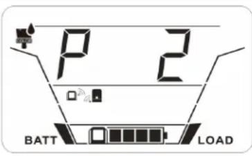 | On-Off RGB LED Bottom Bank | LED off LED on (default) | ELET |
Energy saving | |||
 | Brightness of RGB LED Front Bank | Low Normal | b100+ |
High (default) | |||
8. Operation
| Program Description Selectable option | |||
 | Brightness of RGB LED Bottom Bank | Low Normal  | b70F |
High (default)  | |||
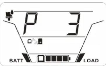
 | Scrolling Speed for RGB LED Front Bank | Low Normal (default)  | 570F |
High  | |||
 | Scrolling Speed for RGB LED Bottom Bank | Low Normal (default)  | 570F |
High  | |||
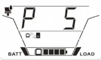
 | RGB LED Front Bank Effects | Power bar Power color shift  | nPCS |
Power fade Solid(default)  | nSQL | ||
Breath Scrolling  | nSCT | ||
Spectrum cycling Spark  | nSPF | ||
8. Operation
| Program Description Selectable option | |||
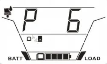
 | RGB LED Bottom Bank Effects | Power fade Solid(default) |  |
Breath | Spectrum cycling | ||
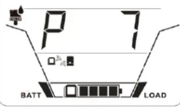
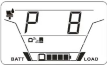
 | Color1 RGB LED Front Bank | Red Orange |  |
Yellow Green |  | ||
Aqua Blue (default) |  | ||
Purple White |  | ||
Configured via software | |||
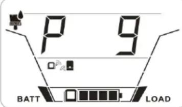
 | Color2 RGB LED Front Bank | Red (default) Orange |  |
Yellow Green |  | ||
Aqua Blue |  | ||
Purple White |  | ||
Configured via software | |||
8. Operation
| Program Description Selectable option | |||
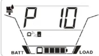
 | Color1 RGB LEDBottom Bank | Red Orange |  |
Yellow Green |  | ||
Aqua Blue (default) |  | ||
Purple White |  | ||
Configured via software | |||
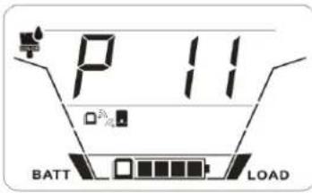
 | Color2 RGB LEDBottom Bank | Red (default) Orange |  |
Yellow Green |  | ||
Aqua Blue |  | ||
Purple White |  | ||
Configured via software | |||
8. Operation
| Program Description Selectable option | |||
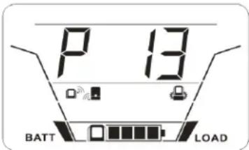 | On-Off Eco Mode | Eco Mode On Eco Mode Off (default) | |
 |  | ||
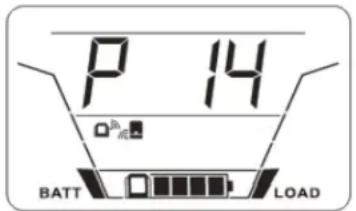 Appears on SMART1500PSGLCD only. Appears on SMART1500PSGLCD only. | Turn the BP24V9T External Battery On and Off (SMART1500PS- GLCD only) | BP24V9T On BP24V9T Off (default) | |
 |  | ||
9. Troubleshooting
When there is a fault, error, warning, or alarm, both the front and bottom LED banks will flash red. If the UPS system does not operate correctly, use the following table to identify the problem.
| Problem/Fault code Possible Cause/Fault Event Solutions | ||
| UPS will not turn on after pressing On/Off button. | Releasing the On/Off button too quickly. | Press and hold the “On/Off” button for at least 2 seconds, then release. |
| The mains supply is normal, but the UPS is operating in battery mode. | Power cord is loose. Reconnect AC | input power cord. |
| Circuit breaker has tripped. Reset the input circuit breaker. If the input circuit breaker trips after the UPS restarts, remove excess loads from the UPS. | ||
| The AC normal icon is illuminated, but there is no output. | The UPS has an internal fault. Disconnect the computer cable from the UPS and press the On button. If UPS functions normally, the software has control of the UPS. | |
| Battery backup time is shorter than nominal value. | Batteries are not fully charged. Charge the batteries for at least 5 hours, then check capacity. If the problem persists, contact your dealer. | |
| Battery defect. Contact your dealer to replace the battery. | ||
Fault code E12 and  icon is on. icon is on. | Output voltage is too high on battery mode. | Contact your dealer. |
Fault code E13 and  icon is on. icon is on. | Output voltage is too low on battery mode. | Contact your dealer. |
Warning code E32 and  icon is flashing. icon is flashing. | Communication lost between UPS and Base. | Contact your dealer. |
Warning code E32 and  icon flashes. icon flashes. | The distance between remote panel and the docking base is out of wireless transmission range. | Reduce the distance between the remote panel and the docking base. |
| Error occurs with the pairing password. | Quick-press the “On/Off” button 5 times to reset pairing, then connect the remote panel to the docking base. | |
Fault code E14 and  icon is on. icon is on. | Output is short-circuited. Check if connected devices are in short-circuit status. Disconnect short-circuited loads and restart the UPS. | |
Fault code E15 and  icon is on. icon is on. | Overcurrent on output. Reduce the connected load by switching off some equipment. | |
Fault code E20 and  icon is on icon is on | Fan lock fault. Contact your dealer. | |
| Fault code E21 Overcharge voltage. | Contact your dealer. | |
Fault code E28 and  icon is on icon is on | Main internal UPS battery low. | The battery requires replacement. If the fault still occurs after battery replacement, contact your dealer. |
Fault code E43 and  icon is on icon is on | Overload fault. | Contact your dealer. |
 icon is illuminate and the alarm sounds continuously. icon is illuminate and the alarm sounds continuously. | The UPS has an internal problem. | Contact your dealer. |
10. Specifications
| Model SMART600PSGLCD | SMART1000PSGLCD | SMART1200PSGLCD | SMART1500PSGLCD | |
| Nominal voltage and input range | 120V~, 97-145V 120V~, | 97-145V 120V~, 97-145V | 120V~, 97-145V | |
| Nominal input frequency and tolerance | 50/60 Hz (Frequency low/comeback: 45/47Hz±0.2Hz; or 55/57Hz±0.2Hz; Frequency high/comeback: 55/53Hz±0.2Hz; 65/63Hz±0.2Hz) | 50/60 Hz (Frequency low/comeback: 45/47Hz±0.2Hz; or 55/57Hz±0.2Hz; Frequency high/comeback: 55/53Hz±0.2Hz; 65/63Hz±0.2Hz) | 50/60 Hz (Frequency low/comeback: 45/47Hz±0.2Hz or 55/57Hz±0.2Hz; Frequency high/comeback: 55/53Hz±0.2Hz; 65/63Hz±0.2Hz) | 50/60 Hz (Frequency low/comeback: 45/47Hz±0.2Hz; or 55/57Hz±0.2Hz; Frequency high/comeback: 55/53H±0.2Hz; 65/63Hz±0.2Hz) |
| Nominal output voltage: 120V~ in line mode and 120V~ battery | 120V~ in line mode and 120V~ battery | 120V~ in line mode and 120V~ battery | 120V~ in line mode and 120V~ battery | |
| Nominal output frequency | 50/60 Hz (50Hz ±2% / 60Hz ±1.67%) | 50/60 Hz (50Hz ±2% / 60Hz ±1.67%) | 50/60 Hz (50Hz ±2% / 60Hz ±1.67%) | 50/60 Hz (50Hz ±2% / 60Hz ±1.67%) |
| Output voltage regulation in line mode | 120V~ (±10%) 120V~ (±10%) 120V~ (±10%) 120V~ (±10%) | 120V~ (±10%) 120V~ (±10%) 120V~ (±10%) | 120V~ (±10%) | |
| Output voltage regulation in battery mode | 120V~ (±10%) 120V~ (±10%) 120V~ (±10%) 120V~ (±10%) | 120V~ (±10%) 120V~ (±10%) 120V~ (±10%) | 120V~ (±10%) | |
| Nominal output power in W / VA | 360W / 600VA 600W / 1000VA 720W / 1200VA 900W / 1500VA | |||
| Output voltage waveform Sinusoidal in line mode and Sinusoidal in battery mode | Sinusoidal in line mode and Sinusoidal in battery mode | Sinusoidal in line mode and Sinusoidal in battery mode | Sinusoidal in line mode and Sinusoidal in battery mode | |
| Maximum output current @ P. F. | 5A @ 120V~ 8.3A @ 120V~ 10A @ 120V~ 12A @ 120V~ | |||
| Maximum output P.F. P.F. = 0.6 | ||||
| Efficiency with nominal load | ≥96% | ≥96% | ≥96% | ≥96% |
| Efficiency at rated load | ≥96% | ≥96% | ≥96% | ≥96% |
| Maximum operating altitude at 100% of nominal power | 9842 ft. (3000 m) | 9842 ft. (3000 m) | 9842 ft. (3000 m) | 9842 ft. (3000 m) |
| Online overload capability | 110%+15%/-5% for 5 minutes; 120%+15%/-5% immediately and go to fault | 110%+15%/-5% for 5 minutes; 120%+15%/-5% immediately and go to fault | 110%+15%/-5% for 5 minutes; 120%+15%/-5% immediately and go to fault | 110%+15%/-5% for 5 minutes; 120%+15%/-5% immediately and to fault |
| Overload capacity in battery mode | 110%+15%/-5% for 10 seconds; 120%+15%/-5% Shutdown immediately | 110%+15%/-5% for 10 seconds; 120%+15%/-5% Shutdown immediately | 110%+15%/-5% for 10 seconds; 120%+15%/-5% Shutdown immediately | 110%+15%/-5% for 10 seconds; 120%+15%/-5% Shutdown immediately |
| Current limitation: | 10A @ 120V~ 10A @ 120V~ 10A @ 120V~ 15A @ 120V~ | |||
| Autonomy time at full load | 2.5 minutes @ 360W 2 minutes @ 600W 2.5 minutes @ 720W 3 minutes @ 900W | |||
| Battery recharge time | 7 hours | 7 hours | 7 hours | 7 hours |
| Transfer time | 6ms Typical, 10ms Max | 6ms Typical, 10ms Max | 6ms Typical, 10ms Max | 6ms Typical, 10ms Max |
| Outlets | 4x 5-15R outlets with battery backup and surge; 4x 5-15R outlets surge only | 4x 5-15R outlets with battery backup and surge; 4x 5-15R outlets surge only | 5x 5-15R outlets with battery backup and surge; 5x 5-15R outlets surge only | 5x 5-15R outlets with battery backup and surge; 5x 5-15R outlets surge only |
| Maximum input current | 5A @ 120V~ 8.3A @ 120V~ 10A @ 120V~ 12A @ 120V~ | |||
Specifications are subject to change without further notice.
11. Storage and Service
Storage
To avoid battery drain, all connected equipment should be turned off and disconnected from the UPS. Press the power button and disconnect the unit from AC power. Your UPS will be completely turned off (deactivated) and will be ready for storage. If you plan on storing your UPS for an extended period, fully recharge the UPS batteries every 3 months. Plug the UPS into a live AC outlet, and allow the batteries to recharge for 4 to 6 hours. If you leave your UPS batteries discharged for a long period of time, they will suffer a permanent loss of capacity.
Service
A variety of Extended Warranty and On-Site Service Programs are available from Tripp Lite. For more information on service, visit tripplite.com/support.
Before returning your product for service, follow these steps:
- Review the installation and operation procedures in this manual to ensure that the service problem does not originate from a misreading of the instructions.
- If the problem continues, do not contact or return the product to the dealer. Instead, visit tripplite.com/support.
- If the problem requires service, visit tripplite.com/support and click the Product Returns link. From here you can request a Returned Material Authorization (RMA) number, which is required for service. This simple on-line form will ask for your unit's model and serial numbers, along with other general purchaser information. The RMA number, along with shipping instructions, will be emailed to you. Any damages (direct, indirect, special or consequential) to the product incurred during shipment to Tripp Lite or an authorized Tripp Lite service center is not covered under warranty. Products shipped to Tripp Lite or an authorized Tripp Lite service center must have transportation charges prepaid. Mark the RMA number on the outside of the package. If the product is within its warranty period, enclose a copy of your sales receipt. Return the product for service using an insured carrier to the address given to you when you request the RMA.
12. Product Registration
Visit tripplite.com/warranty today to register your new Tripp Lite product. You'll be automatically entered into a drawing for a chance to win a FREE Tripp Lite product! *
* No purchase necessary. Void where prohibited. Some restrictions apply. See website for details.
13. Regulatory Compliance
FCC Notice, Class B
This device complies with part 15 of the FCC Rules. Operation is subject to the following two conditions: (1) This device may not cause harmful interference, and (2) this device must accept any interference received, including interference that may cause undesired operation.
Note: This equipment has been tested and found to comply with the limits for a Class B digital device, pursuant to part 15 of the FCC Rules. These limits are designed to provide reasonable protection against harmful interference in a residential installation. This equipment generates, uses and can radiate radio frequency energy and, if not installed and used in accordance with the instructions, may cause harmful interference to radio communications. However, there is no guarantee that interference will not occur in a particular installation. If this equipment does cause harmful interference to radio or television reception, which can be determined by turning the equipment off and on, the user is encouraged to try to correct
the interference by one or more of the following measures:
- Reorient or relocate the receiving antenna.
- Increase the separation between the equipment and receiver.
- Connect the equipment into an outlet on a circuit different from that to which the receiver is connected.
- Consult the dealer or an experienced radio/TV technician for help.
Any changes or modifications to this equipment not expressly approved by Tripp Lite could void the user's authority to operate this equipment.
RF Exposure Warning
The equipment complies with FCC RF exposure limits set forth for an uncontrolled environment. The equipment must not be co-located or operating in conjunction with any other antenna or transmitter.
Canada, Industry Canada (IC) Notices
This device complies with Canada license-exempt RSS standard(s). Operation is subject to the following two conditions: (1) this device may not cause interference, and (2) this device must accept any interference, including interference that may cause undesired operation of the device.
Radio Frequency (RF) Exposure Information
The radiated output power of the Wireless Device is below the Industry Canada (IC) radio frequency exposure limits. The Wireless Device should be used in such a manner such that the potential for human contact during normal operation is minimized.
This device has also been evaluated and shown compliant with the IC RF Exposure limits under portable exposure conditions. (antennas are less than 20 cm of a person's body).
Innovation, Science and Economic Development Canada CS-03 Statement
This product meets the applicable Innovation, Science and Economic Development Canada technical specifications. The Ringer Equivalence Number (REN) indicates the maximum number of devices allowed to be connected to a telephone interface. The termination of an interface may consist of any combination of devices subject only to the requirement that the sum of the RENs of all the devices not exceed five.
The Ringer Equivalence Number (REN) is 0.1.
Regulatory Compliance Identification Numbers
For the purpose of regulatory compliance certifications and identification, your Tripp Lite product has been assigned a unique series number. The series number can be found on the product nameplate label, along with all required approval markings and information. When requesting compliance information for this product, always refer to the series number. The series number should not be confused with the marking name or model number of the product.
Tripp Lite has a policy of continuous improvement. Product specifications are subject to change without notice. Photos and illustrations may differ slightly from actual products.


Manufacturing Excellence.
1111 W. 35th Street, Chicago, IL 60609 USA • tripplite.com/support
21-06-111 933CF1 50%
1111 W. 35th Street, Chicago, IL 60609 EE UU • tripplite.com/support
natural_image
Line drawing of a power plug connecting two socket outlets (no text or symbols)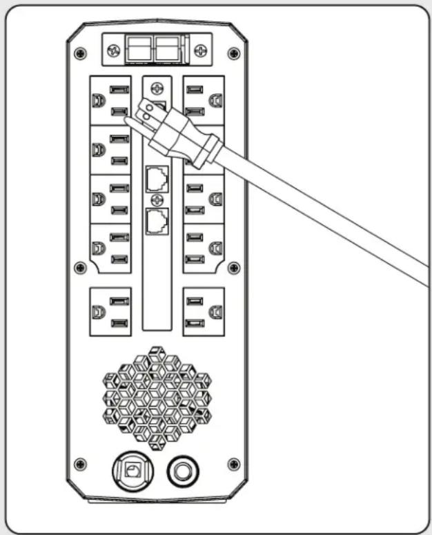
natural_image
Diagram of a server rack with connected ports and a cable inserted, showing no text or symbols5. Instalación
flowchart
graph TD
    A["Step 1: Initial package with two ports"] --> B["Step 2: Box on first port"]
    B --> C["Step 3: Final packaging with two ports"]
1111 W. 35th Street, Chicago, IL 60609 EE UU • tripplite.com/support
21-06-111 933CE1 RevD
1111 W. 35th Street, Chicago, IL 60609 USA • tripplite.com/support

The Ground Truth image displays a single, solid horizontal line. According to Rule 2 (UNDERSCORE & LINE RULES), this is a stylistic or background line, not a placeholder underscore. Therefore, the OCR result must ignore it and output nothing or only meaningful text. The provided OCR content is "____", which consists of four underscores. This is an incorrect interpretation of the line as a placeholder, violating the rule that stylistic lines must be ignored. The OCR has hallucinated underscores where none should exist based on the GT's visual context. Hence, the OCR result is inconsistent with the Ground Truth.
natural_image
Top-down schematic of a device rear panel with ports and connectors (no text or labels)SMART1200PSGLCD
natural_image
Top-down schematic of a device rear panel with ports and connectors (no text or labels)SMART1000PSGLCD SMART600PSGLCD
natural_image
Back panel of a server rack with ports and connectors (no text or symbols visible)
natural_image
Line drawing of a hand inserting two socket plugs into an electrical outlet (no text or symbols)natural_image
Diagram of a server rack with connected ports and a cable inserted, showing no text or symbolsflowchart
graph TD
    A["Step 1: Initial package with two ports"] --> B["Step 2: Box on first port"]
    B --> C["Step 3: Final packaging with two ports"]
1111 W. 35th Street, Chicago, IL 60609 USA • tripplite.com/support

- WARRANTY REGISTRATION
- Important Safety Instructions
- SAVE THESE INSTRUCTIONS
- Transportation
- Preparation
- Installation
- Operation
- Maintenance, Service and Faults
- Battery Warnings
- Storage and Maintenance
- Introduction
- Package Contents
- Product Overview
- Installation
- Quick Start Guide
- Step 1: Plug the UPS into a 120V AC Power Source
- Step 2: Plug Equipment into the UPS
- Optional Installation:
- Remote panel operation
- Battery Replacement
- ECO Energy-Saving Setup
- Enabling ECO Mode
- Operation
- LCD Data Reporting Screens
- UPS Set-Up & LED Programming Mode
- To enter UPS Set-up mode:
- To edit individual programming options:
- Troubleshooting
- Specifications
- Storage and Service
- Storage
- Service
- Product Registration
- Regulatory Compliance
- FCC Notice, Class B
- RF Exposure Warning
- Canada, Industry Canada (IC) Notices
- Radio Frequency (RF) Exposure Information
- Innovation, Science and Economic Development Canada CS-03 Statement
- Regulatory Compliance Identification Numbers
- Instalación
Brand : Tripp Lite
Model : SMART1500PSGLCD
Category : Uninterruptible power supply