S3MT-100K480V - Uninterruptible power supply Tripp Lite - Free user manual and instructions
Find the device manual for free S3MT-100K480V Tripp Lite in PDF.

| Product Type | Input isolation transformer for three-phase inverter |
| Brand | Tripp Lite |
| Model | S3MT-100K480V |
| Nominal Input Voltage | 480 V (Delta) |
| Nominal Output Voltage | 208/120 V (Wye, three-phase 4-wire + PE) |
| Apparent Power (kVA) | 100 kVA |
| Active Power (kW) | 100 kW |
| Maximum Input Current | 168 A |
| Maximum Output Current | 374 A |
| Dimensions (H × W × D) | 1200 × 600 × 850 mm |
| Net Weight | 489 kg |
| Gross Weight (packaged) | 545 kg |
| Full Load Efficiency | 96.5% |
| Half Load Efficiency | 97.5% |
| Insulation Class | 180 °C |
| Operating Temperature | 0 °C to 40 °C |
| Relative Humidity | ≤ 95% (non-condensing) |
| Audible Noise at 1 m | ≤ 65 dB |
| Ventilation | 3 ball bearing fans 172 × 152 mm (total 723 CFM) |
| Protection | Integrated 400 A circuit breaker, thermal protection (160 °C), red LED indicator |
| Enclosure Material | Galvanized steel (SGCC), color RAL 9011 |
| Warranty | 2 years |
| Certifications | cTUVus (UL 1778, CSA 22.2) |
| Package Contents | Transformer, user manual, bottom skirts, screws |
Frequently Asked Questions - S3MT-100K480V Tripp Lite
User questions about S3MT-100K480V Tripp Lite
0 question about this device. Answer the ones you know or ask your own.
Ask a new question about this device
Download the instructions for your Uninterruptible power supply in PDF format for free! Find your manual S3MT-100K480V - Tripp Lite and take your electronic device back in hand. On this page are published all the documents necessary for the use of your device. S3MT-100K480V by Tripp Lite.
USER MANUAL S3MT-100K480V Tripp Lite
S3MT-60K480V, S3MT-100K480V, S3MT-60K600V, S3MT-100K600V
natural_image
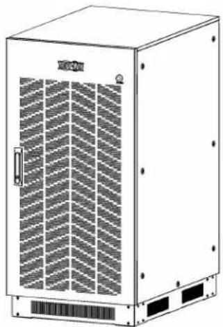
Line drawing of a white industrial control cabinet with ventilation grilles and mounting base (no text or symbols)Español 21 • Français 41
WARRANTY REGISTRATION
Register your product today and be automatically entered to win an ISOBAR ^® surge protector in our monthly drawing!
tripplite.com/warranty


Manufacturing Excellence.
1111 W. 35th Street, Chicago, IL 60609 USA • tripplite.com/support
Copyright © 2021 Tripp Lite. All rights reserved.
Table of Contents
- Introduction ...... 3
- Important Safety Warnings....5
- Installation 6
3.1 Mechanical Data....6
3.2 Package Inspection ....7
3.3 Unpacking the UPS 7
3.4 Package Contents ......9
3.5 Cabinet Overview....10
3.6 Power Cables 12
3.7 Transformer-to-UPS Connection Line Diagram ....13
3.8 Multiple Transformer Connections....15
3.8.1 S3MT-60K480V/S3MT-60K600V to S3M50K or S3M60K UPS....15
3.8.2 S3MT-100K480V/S3MT-100K600V to S3M80K or S3M100K UPS....15
- Operations....16
4.1 Over-Temperature Protection....16
4.1.1 Over-Temperature Red Warning LED Light 16
4.1.2 Over-Temperature Protection Relay and Thermal Switch.... 16 - Specifications.... 17
- Storage....19
- Warranty and Regulatory Compliance....19
1. Introduction
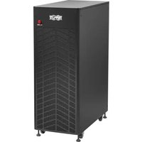
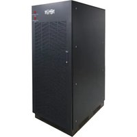
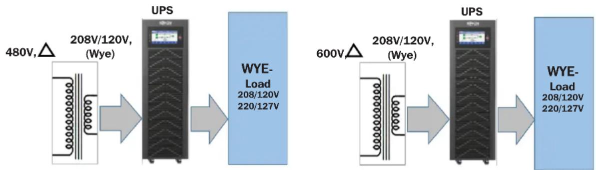
Tripp Lite's S3MT-60K480V and S3MT-100K480V input isolation transformers provide 480V (Delta) to 208V (Wye) step-down and Isolation protection to the connected UPS and its load. The S3MT-60K600V and S3MT-100K600V Input isolation transformers provide 600V (Delta) to 208V (Wye) step-down and isolation protection to the connected UPS and its load.
The transformer has input isolation to mitigate utility line surges and spikes, while protecting the UPS. The transformer includes a built in breaker at the transformer output side for protection. The ball-bearing fans maintain quiet operation (four fans for 60K models, three large fans for 100K models). An overheat-sensing relay and switch combine with a warning light to provide over-temperature warning and overheating protection. The UPS system's small footprint and quiet acoustic profile enable installations with minimal space and noise impact. All transformer models feature rugged stainless steel housings with front panels similar to the S3M-Series 208V 3-Phase UPS line.
| UPS Model Series Number Capacity Description | |||
| S3MT-60K480V AG-05 | 0D 60kW 480V to 208V | Input Isolation Transformer | |
| S3MT-100K480V AG-05 | 510 100kW 480V to 208V | Input Isolation Transformer | |
| S3MT-60K600V AG-05 | 0F 60kW 600V to 208V | Input Isolation Transformer | |
| S3MT-100K600V AG-05 | 50E 100kW 600V to 208V | Input Isolation Transformer | |
Typical applications
4-Wire (3Ph+N+PE) IT equipment loads in government, manufacturing, hospitals, industrial settings and corporate settings that have 480V or 600V electrical mains and 208V/120V or 220V/127V IT Loads.
Key Features
- Isolation protection to the UPS input, with stepped-down input from 480V (Delta) to 208V/120V (Wye) or 600V (Delta) to 208V/120V (Wye)
- Circuit breaker and overheating protection
• 96.5% to 97.5% efficiency - Wide input voltage and frequency operating range: Voltage: -20% to +25% @ 100% load and 40-70 Hz
• Insulation class: 180°C material - Reliability-tested according to ISTA-3B for vibration, shock, drop (tip test)
• UL and CSA TUV certifications - Rugged stainless steel housing shipped ready for installation
- 2-year warranty
1. Introduction
Typical Configurations
flowchart
graph LR
    A["480V, △"] --> B["UPS"]
    B --> C["WYE-Load 208/120V 220/127V"]
    D["600V △"] --> E["UPS"]
    E --> F["WYE-Load 208/120V 220/127V"]
    style A fill:#f9f,stroke:#333
    style B fill:#ccf,stroke:#333
    style C fill:#cfc,stroke:#333
    style D fill:#fcc,stroke:#333
    style E fill:#cff,stroke:#333
    style F fill:#ffc,stroke:#333
These 480V Input Transformers may be purchased separately or as part of kit model with a Tripp Lite S3M Series 3-Phase UPS:
| InputTransformer Models | MaximumConstant Load | Compatible with208V 3Ph UPS | Kit Models: UPS + Transformer | ||
| Kit Models Kit Models Include | |||||
| 480V | S3MT-60K480V 60kW 50-60kW UPS | S3M50K-60K4T | S3M50K UPS + S3MT-60K480V | ||
| S3M60K-60K4T | S3M60K UPS + S3MT-60K480V | ||||
| S3MT-100K480V 100kW 80-100kW UPS | S3M80K-100K4T | S3M80K UPS + S3MT-100K480V | |||
| S3M100K-100K4T | S3M100K UPS + S3MT-100K480V | ||||
| 600V | S3MT-60K600V 60kW 50-60kW UPS | S3M50K-60K6T | S3M50K UPS + S3MT-60K600V | ||
| S3M60K-60K6T | S3M60K UPS + S3MT-60K600V | ||||
| S3MT-100K600V 100kW 80-100kW UPS | S3M80K-100K6T | S3M80K UPS + S3MT-100K600V | |||
| S3M100K-100K6T | S3M100K UPS + S3MT-100K600V | ||||
2. Important Safety Warnings
SAVE THESE INSTRUCTIONS
This manual contains important instructions for models S3MT-60K480V / S3MT-100K480V / S3MT-60K600V / S3MT-100K600V that should be followed during installation and maintenance of the transformer and UPS.
⚠️ CAUTION! Risk of electrical shock! Hazardous live parts inside this unit are energized from the transformer even when the breaker is turned off.
⚠ WARNING! The unit intended for installation in a controlled environment.
CAUTION! A transformer can present a risk of electric shock and high short circuit current. The following precaution should be observed when working on the transformer:
- Remove watches, rings or other metal objects.
- Use tools with insulated handles.
To reduce the risk of electric shock, disconnect the transformer and UPS from the mains supply before performing maintenance or service.
Servicing of the 3-phase transformer and UPS should be performed by Tripp Lite certified personnel with knowledge of the 3-phase transformer and UPS and all required precautions.
The transformer is extremely heavy. Caution should be taken in moving and positioning equipment. The instructions contained within this manual are important and should be closely followed at all times during installation and follow-up maintenance of the 3-phase transformer and UPS.

CAUTION!
The transformer has a dangerous level of heat. If the transformer's front-panel red LED indicator is on, the unit's outlets may have a dangerous level of heat.
All servicing on this equipment must be carried out by Tripp Lite-certified service personnel.
Before conducting any maintenance, repair or shipment, first ensure everything is turned off completely and disconnected.
Special Symbols – The following symbols are used on the transformer to warn you of precautions:

RISK OF ELECTRIC SHOCK - Observe the warning that a risk of electric shock is present.

CAUTION - REFER TO THE OWNER'S MANUAL for information regarding important operating and maintenance instructions.

SAFE GROUNDING TERMINAL - Indicates THE primary safe ground.
3. Installation
3.1 Mechanical Data
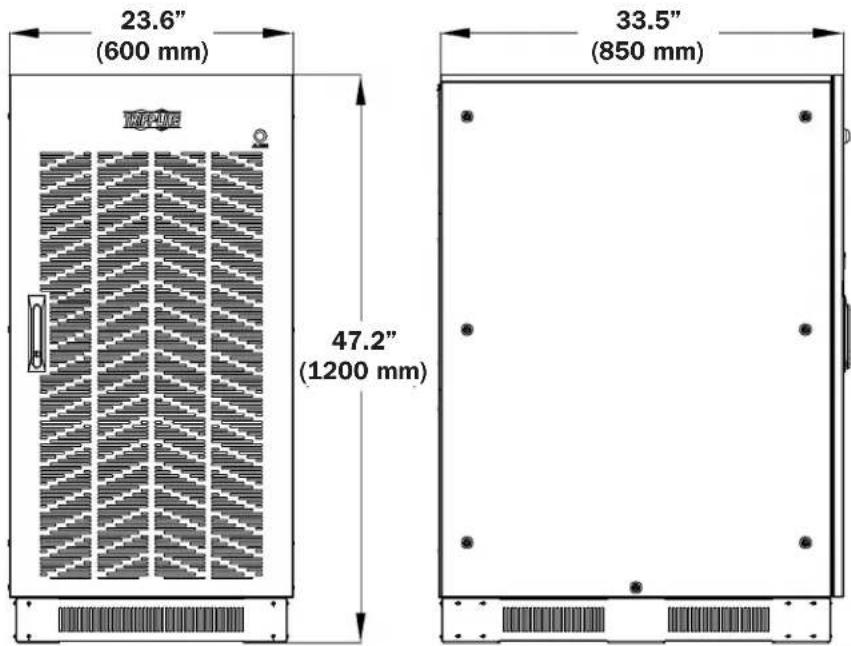
Physical Requirements
Leave space around the cabinet for operation and ventilation (Figure 3-1):
- Leave at least 23.6 in. (600 mm) space in the front for ventilation
- Leave at least 20 in. (500 mm) space at the right and left for operation
- Leave at least 20 in. (500 mm) space at the back for ventilation
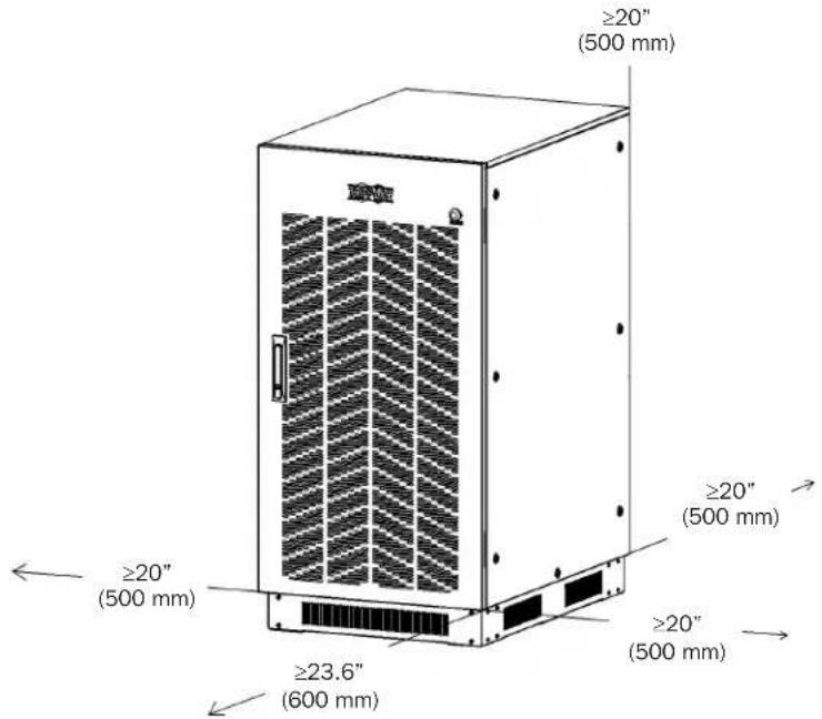
Figure 3-1
3. Installation
3.2 Package Inspection
- Don't lean the transformer cabinet when removing it from the packaging.
- Check the appearance to see if the transformer cabinet was damaged during transport. Do not power on the transformer cabinet if any damage is found. Contact the dealer immediately.
- Check the accessories against the packing list and contact the dealer in case of missing parts.
3.3 Unpacking the UPS
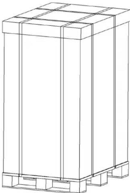
- Hold the sliding plate steady. Cut and remove the binding straps (Figure 3-2).
natural_image
Line drawing of a rectangular industrial container or storage unit with internal compartments (no text or symbols)Figure 3-2
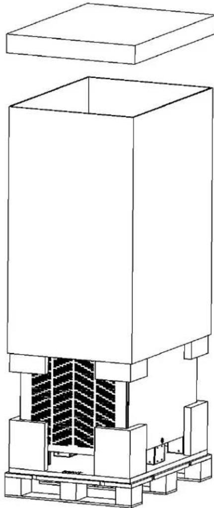
- Remove the plastic bag and the outer carton (Figure 3-3).
natural_image
Technical line drawing of a mechanical assembly with layered components (no text or symbols)Figure 3-3
3. Installation
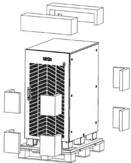
- Remove the foam packing material and the beveled pallet (Figure 3-4).
natural_image
Technical line drawing of a mechanical device with internal heat exchanger and mounting brackets (no text or symbols)Figure 3-4
- Remove the screws securing the cabinet to the pallet (Figure 3-5).
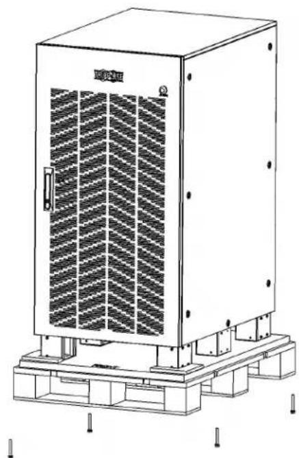
natural_image
Technical line drawing of a large industrial control cabinet with ventilation grilles and mounting base (no text or symbols)Figure 3-5
- Lift the cabinet with a forklift and remove the packing pallets (Figure 3-6).
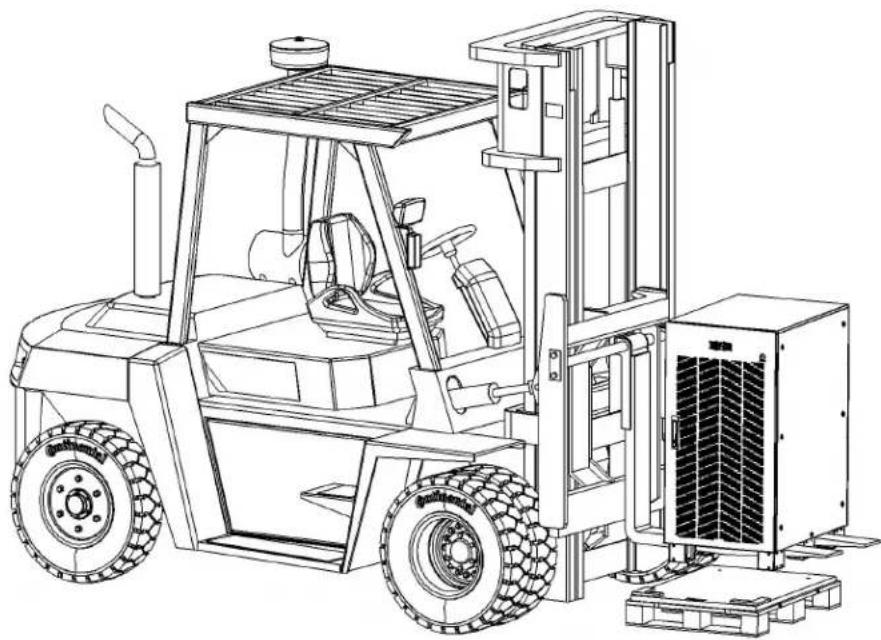
natural_image
Line drawing of a forklift carrying a control unit (no text or symbols present)Figure 3-6
3. Installation
3.4 Package Contents
| Contents TL P/N S3MT-60K480V S3MT-60K600V S3MT-100K480V S3MT-100K600V | ||||
| Input Transformer 1 1 1 1 | ||||
| Owner's Manual 933D05 1 1 1 1 | ||||
| Bottom Skirts 103922A 2 2 2 2 | ||||
| Bottom Skirts 103923A 2 2 2 2 | ||||
| Screws for Skirts 3011C3 24 24 24 24 | ||||
3. Installation
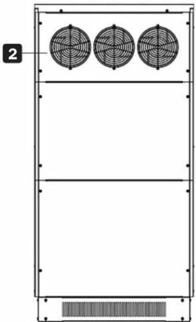
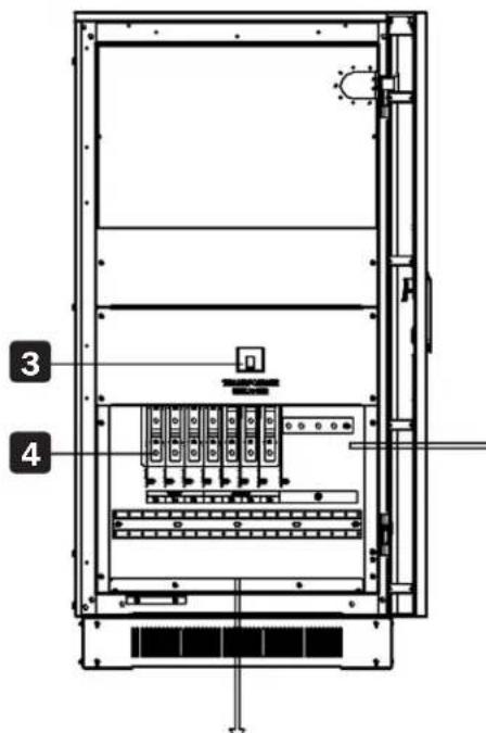
3.5 Cabinet Overview
1 Over-Temperature Alarm LED
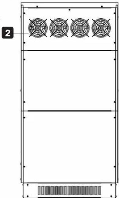
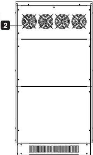
2 Cooling Fans
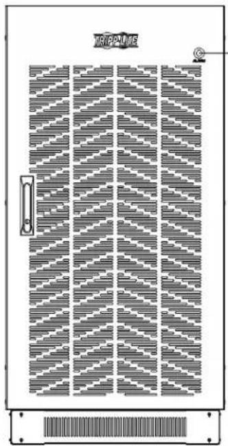
natural_image
Technical diagram of a door with patterned panel and control panel (no text or symbols)Front View
3 Breaker with Trip
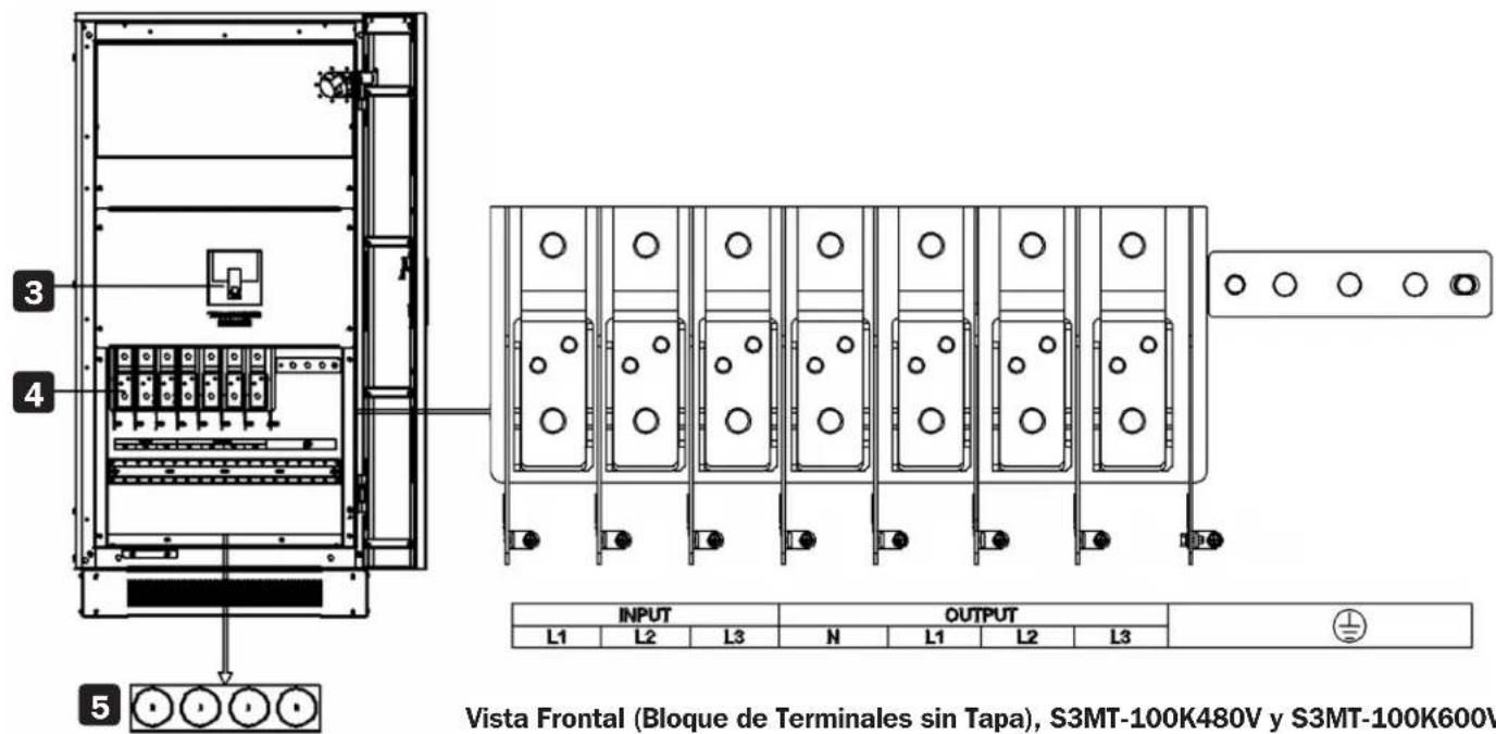
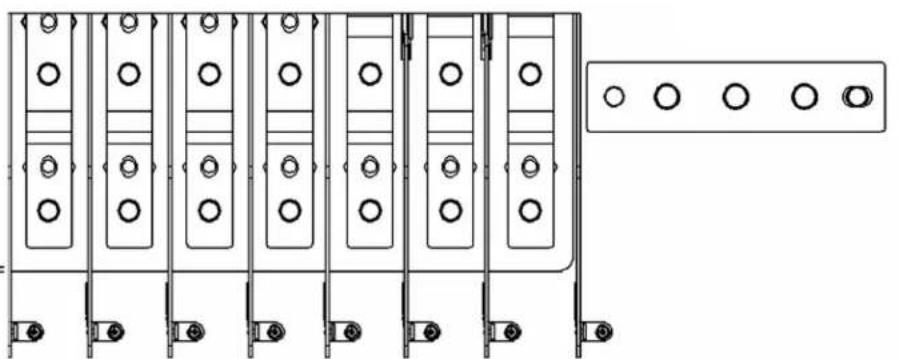
4 Cabling Terminals
1
natural_image
Pure technical diagram of a rectangular panel with four circular fans and a bottom bar, no text or symbols present.Rear View,
S3MT-60K480V / S3MT-60K600V
5 Bottom Entry Knockouts (for Power Cable Entry and Exit)
natural_image
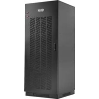
Technical diagram of a rectangular enclosure with three circular fans and a base panel (no text or symbols)Rear View,
S3MT-100K480V / S3MT-100V600V
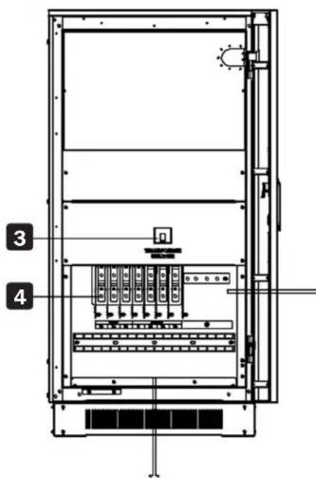
5

natural_image
Technical line drawing of a multi-chamber electrical panel with mounting holes and a separate panel with four circular buttons (no text or symbols)| INPUT | OUTPUT | ||||||
| L1 | L2 | L3 | N | L1 | L2 | L3 | |
Front View (Terminal Block without Cover), S3MT-60K480V / S3MT-60K600V
3. Installation

3. Installation
3.6 Power Cables
The cable design shall comply with the voltages and currents provided in this section, and in accordance with local electrical codes.

WARNING!
UPON STARTUP, ENSURE YOU ARE AWARE OF THE LOCATION AND OPERATION OF THE EXTERNAL ISOLATORS CONNECTED TO THE UPS INPUT/BYPASS SUPPLY OF THE UTILITY DISTRIBUTION PANEL.
ENSURE THESE SUPPLIES ARE ELECTRICALLY ISOLATED AND POST ANY NECESSARY WARNING SIGNS TO PREVENT INADVERTENT OPERATION.
Cable Sizes
| UPS Model | Cable Sizes (THHW wiring at 75°C) | ||||||||
| AC Input AC Output Neutral Grounding Lug | |||||||||
| Gauge Torque Gauge Torque Gauge Torque Gauge Torque | |||||||||
| S3MT-60K480V | 50mm^2 Max. 50mm^2x2 | 25N·m | 50mm^2 Max. 50mm^2x2 | 25N·m | 70mm^2x2 Max. 70mm^2x2 | 25N·m | 50mm^2 Max. 50mm^2x2 | 25N·m M8 | |
| S3MT-60K600V | 35mm^2 Max. 50mm^2x2 | 25N·m | 50mm^2 Max. 50mm^2x2 | 25N·m | 70mm^2x2 Max. 70mm^2x2 | 25N·m | 50mm^2 Max. 5Omm^2x2 | 25N·m M8 | |
| S3MT-100K480V | 70mm^2x2 Max. 120mm^2x2 | 50N·m | 70mm^2x2 Max. 95mm^2x2 | 50N·m | 120mm^2x2 Max. 120mm^2x2 | 50N·m | 95mm^2 Max. 120mm^2 | 50N·m M10 | |
| S3MT-100K600V | 50mm^2 Max. 70mm^2x2 | 50N·m | 70mm^2x2 Max. 95mm^2x2 | 50N·m | 120mm^2x2 Max. 120mm^2x2 | 50N·m | 95mm^2 Max. 120mm^2 50N·m M10 | ||
3. Installation
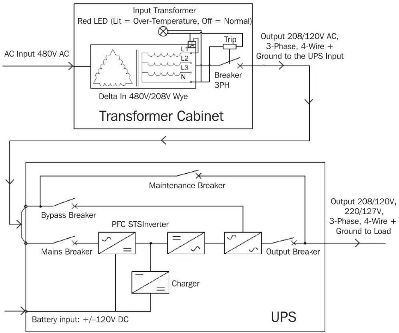
3.7 Transformer-to-UPS Connection Line Diagram
Connections are shown below for the cabinet with built-in input isolator transformer, breakers and the red over-temperature LED.
flowchart
graph TD
    A["AC Input 480V AC"] --> B["Input Transformer"]
    B --> C["Red LED (Lit = Over-Temperature, Off = Normal)"]
    C --> D["Delta In 480V/208V Wye"]
    D --> E["Transformer Cabinet"]
    E --> F["Output 208/120V AC, 3-Phase, 4-Wire + Ground to the UPS Input"]
    F --> G["Maintenance Breaker"]
    G --> H["Bypass Breaker"]
    H --> I["PFC STSInverter"]
    I --> J["Mains Breaker"]
    J --> K["Charger"]
    K --> L["Battery input: +/-120V DC"]
    L --> M["UPS"]
    M --> N["Output 208/120V, 220/127V, 3-Phase, 4-Wire + Ground to Load"]
    N --> O["Output Breaker"]
    O --> P["Breaker 3PH"]
    P --> Q["L1 L2 L3 N"]
    Q --> R["Trip"]
Figure 3-7: Connection Line Diagram for S3MT-60K480V / S3MT-100K480V
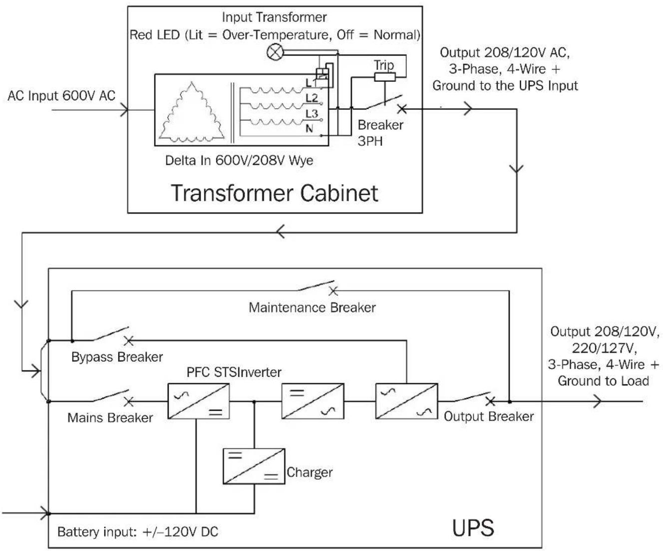
3. Installation
flowchart
graph TD
    A["AC Input 600V AC"] --> B["Input Transformer"]
    B --> C["Red LED (Lit = Over-Temperature, Off = Normal)"]
    C --> D["Delta In 600V/208V Wye"]
    D --> E["Transformer Cabinet"]
    E --> F["Output 208/120V AC, 3-Phase, 4-Wire + Ground to the UPS Input"]
    E --> G["Maintenance Breaker"]
    G --> H["Bypass Breaker"]
    H --> I["PFC STSInverter"]
    I --> J["Mains Breaker"]
    J --> K["Charger"]
    K --> L["Output Breaker"]
    L --> M["Output 208/120V, 220/127V, 3-Phase, 4-Wire + Ground to Load"]
    N["Battery input: +/-120V DC"] --> I
Figure 3-8: Connection Line Diagram for S3MT-60K600V/ S3MT-100K600V
3. Installation
3.8 Multiple Transformer Connections

WARNING: The transformer output neutral is not bonded to chassis ground. Please provide a means to connect the transformer chassis ground to the transformer output neutral.
Note: The transformer chassis ground must be connected to earth ground.

IMPORTANT: You may view and/or download this manual from the tripplite.com website to view the cable connections in colors.
3.8.1 Connections for S3MT-60K480V/S3MT-60K600V to S3M50K or S3M60K UPS
Transformer input is Delta 3-Wire (3Ph + Ground) And transformer output is Wye 4-Wire (3Ph + N + Ground).
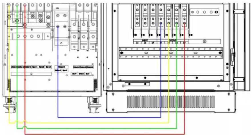
Figure 3-8: UPS (Rear View)
Transformer Cabinet (Front View)
3.8.2 Connections for S3MT-100K480V/S3MT-100K600V to S3M80K or S3M100K UPS
Transformer input is Delta 3-Wire (3Ph + Ground) And transformer output is Wye 4-Wire (3Ph + N + Ground).
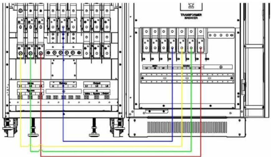
Figure 3-9: UPS (Rear View)
Transformer Cabinet (Front View)
4. Operation

WARNING: It is not advised to connect two UPS in parallel when using individual transformers for each UPS.
4.1 Over-Temperature Protection
4.1.1 Over-Temperature Red Warning LED Light
The transformer includes a warning LED light on the top portion of the front panel. The light turns ON when the transformer reaches a temperature of 160^ C ±5^ C, i.e. a range of 155^ C to 165^ C ( 311^ F to 329^ F). The light turns OFF when the transformer cools to a temperature of 125^ C ±5^ C, i.e. a range of 120^ C to 130^ C ( 248^ F to 266^ F).
4.1.2 Over-Temperature Protection Relay and Thermal Switch
The transformer includes an over-temperature protection relay and thermal switch to protect the transformer from overheating. At temperatures of 160^ C ±5^ C, i.e. a range of 155^ C to 165^ C ( 311^ F to 329^ F), an over-temperature protection relay and thermal switch will activate and will open the output breaker of the transformer. Once the transformer temperature has cooled down and the warning LED light has turned OFF, you may manually re-activate (close) the output breaker to restart normal operation.
5. Specifications
| Models S3MT-60K480V S3MT-60K600V S3MT-100K480V S3MT-100K600V | ||||
| Description | 3-Phase 60k Input Isolation Transformer, Delta 480V/208V Wye | 3-Phase 60k Input Isolation Transformer, Delta 600V/208V Wye | 3-Phase 100k Input Isolation Transformer, Delta 480V/208V Wye | 3-Phase 100k Input Isolation Transformer, Delta 600V/208V Wye |
| Transformer Type Dry-Type | ||||
| Input | ||||
| Input Voltage 480V 600V 480V 600V | ||||
| Input Voltage Operational Range and De-Rating | -45%, +25% at 40 % Load -20%, +25% at 100 % Load | |||
| Input Amps 101A 81A 168A 134A | ||||
| Input Connections 3-Wire (L1, L2, L3, +PE) | ||||
| Input Configuration Delta | ||||
| Input Connection Type Copper Bar | ||||
| Rated AC Input Frequency 50/60 Hz | ||||
| Frequency Range and Derating | 40~70 Hz | |||
| Voltage Selection | No | |||
| Voltage Drop: Ratio Output, No Load to Full Load | ≤3% | |||
| Inrush Current | ≤900A (10 ms) | ≤710A (10 ms) | ≤3330A (10 ms) | ≤1160A (10 ms) |
| Input Isolation | Yes | |||
| Output | ||||
| VA Rating | 60kVA | 60kVA | 100kVA | 100kVA |
| Transformer Output Voltage | 208/120V, (3-Phase, 4-Wire) | |||
| Output Amps | 225A | 374A | ||
| Transformer Output Breaker Rating | 250A 250A 400A 400A | |||
| Output Watts Detailed | 60,000W | 60,000W | 100,000W | 100,000W |
| Output Connections | 4-Wire (L1, L2, L3, +PE, +N) | |||
| Output Connection Type | Copper Bar | |||
| Output Configuration | Wye | |||
| Input Tranformer Output Isolation | Yes | |||
| Operation | ||||
| Over-Temperature Warning LED (Red) | Turns ON at 160°C ±5°C, i.e. a range of 155°C to 165°C (311°F to 329°F) Turns OFF at 125°C ±5°C, i.e. a range of 120°C to 130°C (248°F to 266°F) | |||
| Over-Temperature Protection Reset Device | Transformer output turns OFF at temperatures of 160°C ±5°C, i.e. a range of 155°C to 165°C (311°F to 329°F). The transformer output breaker can be turned ON manually when the warning light turns OFF. | |||
| Insulation Class | 180°C | |||
| Temperature Rise | 125°C | |||
| Full Load Efficiency | 96.50% | 96.70% | ||
5. Specifications
| Models S3MT-60K480V S3MT-60K600V S3MT-100K480V S3MT-100K600V | ||||
| Half Load Efficiency 97.50% 97.70% | ||||
| Physical Info | ||||
| Unit Height 47.2 in. (1200 mm) | ||||
| Unit Width 23.6 in. (600 mm) | ||||
| Unit Depth 33.5 in. (850 mm) | ||||
| Unit Weight 789 lb. (358 kg) 789 lb. (358 kg) 1078 lb. (489 kg) 1049 lb. (476 kg) | ||||
| Floor Loading 702 (kg/m2) 702 (kg/m2) 959 (kg/m2) 933 (kg/m2) | ||||
| Unit Carton Height | 55.4 in. (1407 mm) | |||
| Unit Carton Width | 29.9 in. (760 mm) | |||
| Unit Carton Depth | 38.8 in. (985 mm) | |||
| Unit Carton Weight | 855 lb. (388 kg) 899 lb. (408 kg) 1202 lb. (545 kg) 1102 lb. (500 kg) | |||
| Tip-n-Tell Label Included on Overpack Box | Yes | |||
| Environment | ||||
| Audible Noise at 1 m | 65 dB max. | |||
| RH Humidity, Non-Condensing | 95% | |||
| Online Thermal Dissipation, Full Load (BTU/hr) | 7167 | 7167 | 11263 | 11263 |
| Storage Temperature | 5°F to 140°F (-15°C to 60°C) | |||
| Operating Temperature | 32°F to 104°F (0°C to 40°C) | |||
| Operating Elevation | <1000 m for nominal power (over 1000 m, the power de-rating is 1% per 100 m) | |||
| Mechanical | ||||
| Transformer Windings | Aluminum | |||
| Cabinet Material | Cold Rolled Galvanized Steel (SGCC) | |||
| Cabinet Color | RAL 9011 | |||
| Fan (Type/Quantity) | 60K Models: 4x Ball Bearing, 120 mm (576 total CFM)100K Models: 3x Ball Bearing, 172 x 152 mm (723 total CFM) | |||
| Reliability | ||||
| Vibration | ISTA - 3B | |||
| Shock | ISTA - 3B | |||
| Drop | ISTA - 3B (Tip Test) | |||
| Agency Approvals | ||||
| Approving Agency | cTUVs | |||
| Agency Standard Tested | UL 1778 5th Edition | |||
| Canadian Approvals | CSA 22.2-107.3-14 | |||
| CE Approvals | N/A | |||
| EMI Approvals | N/A | |||
| RoHS/REACH | Yes | |||
6. Storage
Before storing the isolation transformer, ensure all connections have been disconnected and all breakers are turned OFF. Replace all input or output access covers to avoid damaging any contacts.
The transformer must be stored in a clean, secure environment with temperatures between 5^ F to 140^ F ( -15^ C to 60^ C) and relative humidity less than 90% (non-condensing).
Store the transformer in its original shipping container, if possible.

WARNING: The transformer(s) is/are very heavy. Before storing the transformer, make sure to take into account the floor loading (kg/m ^2 ) requirements listed in section 5. Specifications under “Physical Info” to store safely.
7. Warranty and Regulatory Compliance
Limited Warranty
Seller warrants this product, if used in accordance with all applicable instructions, to be free from original defects in material and workmanship for a period of 2 years from the date of initial purchase. If the product should prove defective in material or workmanship within that period, Seller will repair or replace the product, in its sole discretion. Service under this Warranty includes parts only. International customers should contact Tripp Lite support at intlservice@tripplite.com. Continental USA customers should contact Tripp Lite Customer Service at 773-869-1234 or visit tripplite.com/support/help
THIS WARRANTY DOES NOT APPLY TO NORMAL WEAR OR TO DAMAGE RESULTING FROM ACCIDENT, MISUSE, ABUSE OR NEGLECT. SELLER MAKES NO EXPRESS WARRANTIES OTHER THAN THE WARRANTY EXPRESSLY SET FORTH HEREIN. EXCEPT TO THE EXTENT PROHIBITED BY APPLICABLE LAW, ALL IMPLIED WARRANTIES, INCLUDING ALL WARRANTIES OF MERCHANTABILITY OR FITNESS, ARE LIMITED IN DURATION TO THE WARRANTY PERIOD SET FORTH ABOVE; AND THIS WARRANTY EXPRESSLY EXCLUDES ALL INCIDENTAL AND CONSEQUENTIAL DAMAGES. (Some states do not allow limitations on how long an implied warranty lasts, and some states do not allow the exclusion or limitation of incidental or consequential damages, so the above limitations or exclusions may not apply to you. This Warranty gives you specific legal rights, and you may have other rights, which vary from jurisdiction to jurisdiction.)
Tripp Lite; 1111 W. 35th Street; Chicago IL 60609; USA
WARNING: The individual user should take care to determine prior to use whether this device is suitable, adequate or safe for the use intended. Since individual applications are subject to great variation, the manufacturer makes no representation or warranty as to the suitability or fitness of these devices for any specific application.
Product Registration
Visit tripplite.com/warranty today to register your new Tripp Lite product. You will be automatically entered into a drawing for a chance to win a FREE Tripp Lite product!* * No purchase necessary. Void where prohibited. Some restrictions apply. See website for details.
WEEE Compliance Information for Tripp Lite Customers and Recyclers (European Union)

Under the Waste Electrical and Electronic Equipment (WEEE) Directive and implementing regulations, when customers buy new electrical and electronic equipment from Tripp Lite they are entitled to:
- Send old equipment for recycling on a one-for-one, like-for-like basis (this varies depending on the country)
- Send the new equipment back for recycling when this ultimately becomes waste
Use of this equipment in life support applications where failure of this equipment can reasonably be expected to cause the failure of the life support equipment or to significantly affect its safety or effectiveness is not recommended.
Tripp Lite has a policy of continuous improvement. Specifications are subject to change without notice. Photos and illustrations may differ slightly from actual products.


1111 W. 35th Street, Chicago, IL 60609 USA • tripplite.com/support
20 08 282 93 3005 Rev4
natural_image
Line drawing of a white industrial electrical cabinet with ventilation grilles and mounting base (no text or symbols)English 1 • Français 41


1111 W. 35th Street, Chicago, IL 60609, EE. UU. • tripplite.com/support
natural_image
Line drawing of a rectangular industrial container or storage unit with no text or symbolsFigura 3-2
natural_image
Technical line drawing of a mechanical device with internal components and mounting base (no text or symbols)Figura 3-3
3. Instalación
natural_image
Technical line drawing of a mechanical device with internal heat exchanger and mounting brackets (no text or symbols)Figura 3-4
natural_image
Technical line drawing of a large industrial control cabinet with ventilation grilles and mounting base (no text or symbols)Figura 3-5
natural_image
Line drawing of a forklift carrying a control unit (no text or symbols present)Figura 3-6
3. Instalación
natural_image
Diagram of a rectangular device with patterned panels and a labeled top section (no readable text or symbols)Vista Frontal
1
natural_image
Pure technical diagram of a rectangular panel with four circular fan symbols and a bottom bar, no text or labels present.Vista Posterior, S3MT-60K480V y S3MT-60K600V

natural_image
Technical diagram of a rectangular enclosure with three circular fans and a base panel (no text or symbols)Vista Posterior, S3MT-100K480V y S3MT-100V600V
5

natural_image
Technical line drawing of a multi-chamber electrical panel with mounting holes and a separate panel with four circular buttons (no text or symbols)| INPUT | OUTPUT | ||||||
| L1 | L2 | L3 | N | L1 | L2 | L3 | |
Vista Frontal (Bloque de Terminales sin Tapa), S3MT-60K480V y S3MT-60K600V
3. Instalación
3. Instalación
natural_image
Line drawing of a white industrial control cabinet with ventilation grilles and mounting base (no text or symbols)English 1 • Español 21


1111 W. 35th Street, Chicago, IL 60609 USA • tripplite.com/support
natural_image
Line drawing of a rectangular industrial container or storage unit with stacked compartments (no text or symbols)Figure 3-2
natural_image
Technical line drawing of a mechanical assembly with layered components (no text or symbols)Figure 3-3
3. Installation
natural_image
Technical line drawing of a mechanical device with internal components and mounting brackets (no text or symbols)Figure 3-4
natural_image
Technical line drawing of a large industrial control cabinet with ventilation grilles and mounting base (no text or symbols)Figure 3-5
natural_image
Line drawing of a forklift carrying a control unit (no text or symbols present)Figure 3-6
3. Installation
natural_image
Diagram of a door with patterned panels and a label 'JOTELONE' (no readable text or symbols beyond label)Vue avant
1
natural_image
Pure technical diagram of a rectangular enclosure with four circular fans and a base bar, no text or symbols present.natural_image
Technical line drawing of a rectangular enclosure with three circular fans and a base panel (no text or symbols)Vue arrière, S3MT-100K480V/S3MT-100V600V

5
natural_image
Technical line drawing of a multi-chamber electrical panel with mounting holes and a separate panel with four circular holes (no text or symbols)| INPUT | OUTPUT | ||||||
| L1 | L2 | L3 | N | L1 | L2 | L3 | |
1111 W. 35th Street, Chicago, IL 60609 USA • tripplite.com/support