
MTP860H - Petrol tiller SCHEPPACH - Free user manual and instructions
Find the device manual for free MTP860H SCHEPPACH in PDF.

| Brand | Scheppach |
| Model | MTP860H |
| Product type | Petrol cultivator |
| Engine | Honda 4-stroke, 196 cc |
| Engine power | 6.5 HP |
| Engine speed | 3600 rpm |
| Working width | 330 / 500 / 800 mm |
| Tine diameter | 350 mm |
| Starting system | Recoil starter |
| Fuel | Unleaded petrol, minimum octane rating 91, max 10% bioethanol |
| Fuel tank capacity | 3.1 L |
| Engine oil | 0.6 L (15W40) |
| Spark plug | NGK BPR6ES |
| Weight | 81 kg |
| Forward speeds | 1st: 4.70 km/h, 2nd: 6.50 km/h |
| Reverse | 3.50 km/h |
| Adjustable handle | Yes, 3 height positions |
| Working depth | Adjustable (adjustment rod) |
| Clutch | Yes, clutch lever with lock |
| Tine protection | Protective cover and discs |
| Transport wheel | Yes, with support |
| Plough function | Yes, share and wheels included |
| Maintenance | Engine and transmission oil change, greasing shafts, cleaning tines |
| Noise level | Hearing protection recommended |
| Delivery contents | Tiller, tines, wheels, handlebars, assembly tools, engine and machine manual |
Frequently Asked Questions - MTP860H SCHEPPACH
User questions about MTP860H SCHEPPACH
0 question about this device. Answer the ones you know or ask your own.
Ask a new question about this device
Download the instructions for your Petrol tiller in PDF format for free! Find your manual MTP860H - SCHEPPACH and take your electronic device back in hand. On this page are published all the documents necessary for the use of your device. MTP860H by SCHEPPACH.
USER MANUAL MTP860H SCHEPPACH
natural_image
Black-and-white photo of a Honda GP 196 tiller with visible blade and rotor, no text or symbols on the machinery itself.MTP860H
| DE | Benzin-BodenhackeOriginalbetriebsanleitung | 9-21 |
| GB | Petrol Power CultivatorTranslation from the original instruction manual | 22-33 |
| FR | Motobineuse à moteur thermiqueTraduction des instructions d'origine | 34-46 |
| PL | Glebogryzarka spalinowatłumaczenie oryginalnej instrukcji obsługi | 47-59 |


ACHTUNG!: Vor Inbetriebnahme die Bedienungsanleitung genau durchlesen! CAUTION!: Read the manual carefully before operating this machine! ATTENTION!: Lire la notice intégralement avant l'utilisation de la machine! UWAGA!: Przed uruchomieniem przeczytaj uważnie instrukcję obsługi!
2
natural_image
Two gray metal automotive casing components with mounting holes and mounting holes, labeled with number 17 (no text or symbols on the casing itself)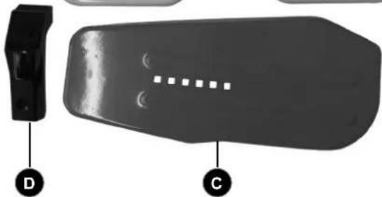
natural_image
Two black plastic objects labeled D and C, one with a curved edge and circular markings, the other with a dotted line and square cutouts (no text or symbols on the objects themselves)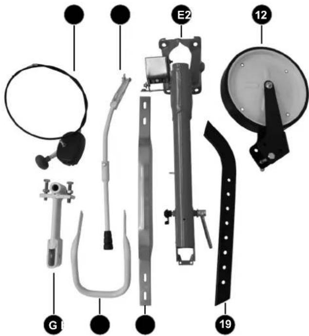
natural_image
Three views of a vehicle tire showing front, side, and side views with labeled components (K, J, and a dot), no text or symbols present.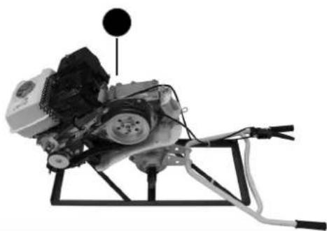
natural_image
Mechanical assembly diagram showing a motor with attached components and wiring (no visible text or symbols)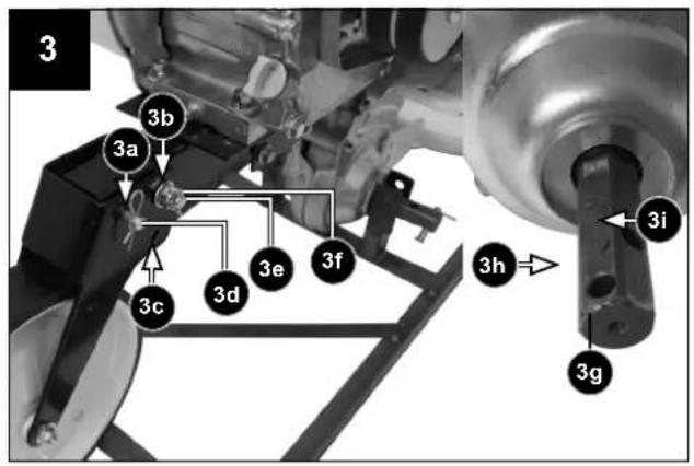
natural_image
Close-up of a mechanical device with a wheel and belt, showing motion direction (no text or symbols)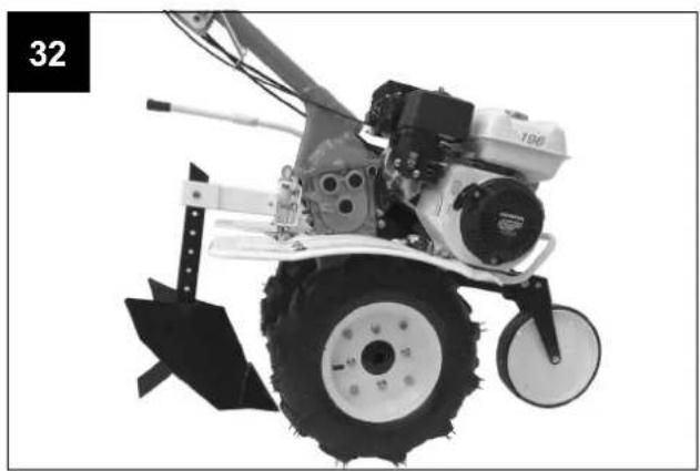
natural_image
Black-and-white photo of a small agricultural tiller with visible blade and wheel, no text or symbols present.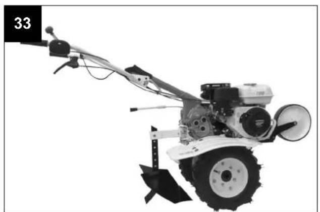
natural_image
Black-and-white photo of a small agricultural tiller with visible blade and bushing (no text or symbols)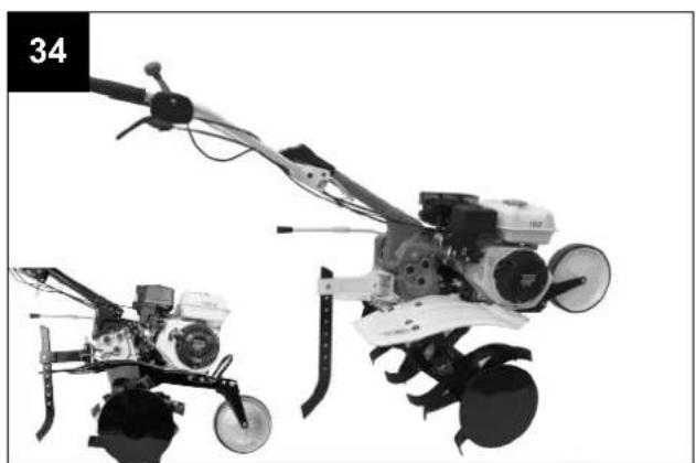
natural_image
Two agricultural tillers shown from different angles, one with visible blade and wheels, the other with a flat blade and wheels (no text or symbols)Description of the symbols
 | Read instruction manual and safety instructions before starting up and pay attention! | |
 | Wear ear protection! | |
 | Wear safety goggles! | |
 | Wear work gloves! | |
 | Wear robust footwear when using the device! | |
 | Open fires forbidden! | |
 | Attention! Do not touch rotating parts. There is serious risk of injury! | |
 | Do not remove or modify protection and safety devices. | |
 | Attention! Hot components - Do not touch | |
 | Risk of catapulted parts if the engine is running.Be sure to keep a safe distance. | |
 | Keep bystanders away from the device! |
1. Introduction
Manufaturer:
scheppach
Günzburger Straße 69
D-89335 Ichenhausen
Dear customer,
We hope your new tool brings you much enjoyment and success.
Note:
According to the applicable product liability laws, the manufacturer of the device does not assume liability for damages to the product or damages caused by the product that occurs due to:
- Improper handling,
• Non-compliance of the operating instructions, - Repairs by third parties, not by authorized service technicians,
- Installation and replacement of non-original spare parts,
• Application other than specified.
We recommend:
Read through the complete text in the operating instructions before installing and commissioning the device.
The operating instructions are intended to help the user to become familiar with the machine and take advantage of its application possibilities in accordance with the recommendations.
The operating instructions contain important information on how to operate the machine safely, professionally and economically, how to avoid danger, costly repairs, reduce downtimes and how to increase reliability and service life of the machine.
In addition to the safety regulations in the operating instructions, you have to meet the applicable regulations that apply for the operation of the machine in your country.
Keep the operating instructions package with the machine at all times and store it in a plastic cover to protect it from dirt and moisture. Read the instruction manual each time before operating the machine and carefully follow its information. The machine can only be operated by persons who were instructed concerning the operation of the machine and who are informed about the associated dangers. The minimum age requirement must be complied with.
In addition to the safety instructions contained in this manual and the special regulations of your country, the technical rules generally accepted for the operation of identical devices must be observed.
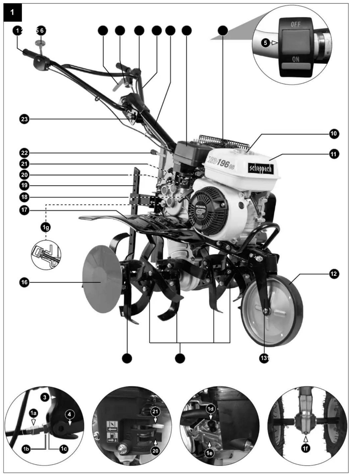
2. Device description (Fig. 1)
- Hand grip
- Throttle trigger
- Clutch lever
- Locking clutch lever
- ON-/OFF Switch
- Handlebar
- Steering column
- Cover air filter
- Cover exhaust
- Fuel filler cap
- Fuel tank
- Support wheel
- Support wheel mounting
- Blades / Tools
- Milling broadening
- Milling protection disc
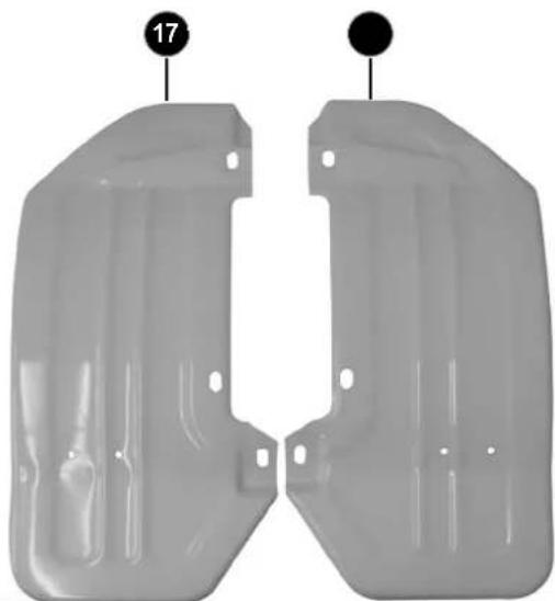
- Milling protection housing
- Start lever
- Fuel tap
- Choke Lever
-
Gear selector lever
-
Jackleg / Working depth regulator
-
Height adjustment Handlebar
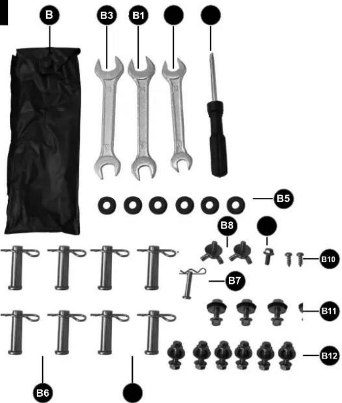
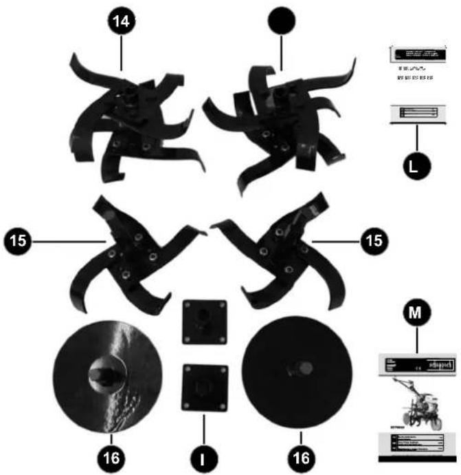
3. Scope of delivery (Fig. 1+2)
A Housing with motor / gearbox and handlebar (1x)
B Bag with mounting material
B1 Hexagon wrench 10/12 (1x)
B2 Hexagon wrench 12/14 (1x)
B3 Hexagon wrench 13/16 (1x)
B4 Screwdriver (1x)
B5 Rubber ring (6x)
B6 Fastening pin large with split pin (8x)
B7 Fastening pin small with split pin (1x)
B8 Wing screw with washer (2x)
B9 Hexagon screw with edge (1x)
B10 Phillips screw (2x)
B11 Hexagon screw with edge, washer and hexagonal nut (4x)
B12 Hexagon screw with edge, washer and hexagonal nut with edge (6x)
C Belt cover (1x)
D Protective cover for handlebar fixation (1x)
E Steering column (7) with gear lever cover (1x)
F Cross connector (1x)
G Mounting point Jackleg / Working depth regulator (1x)
H Front Hand grip (1x)
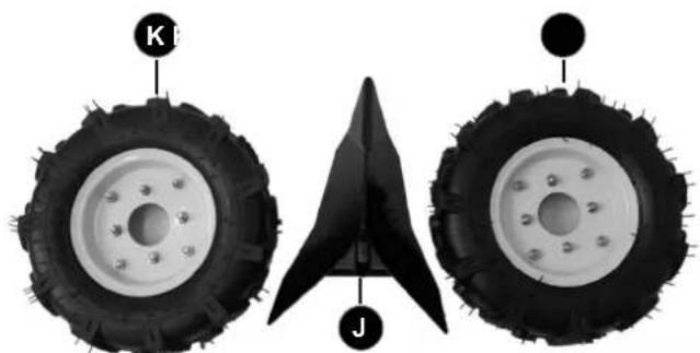
I Wheel mount (2x)
J Plow (1x)
K Wheel (2x)
L Motor manual
M Original instruction manual
2 Throttle trigger (1x)
12 Support wheel (1x)
14 Blades / Tools (2x)
15 Milling broadening (2x)
16 Milling protection disc (2x)
17 Milling protection housing (2x)
19 Jackleg / Working depth regulator (1x)
22 Gear selector lever (1x)
- Open the packaging and remove the device carefully.
- Remove the packaging material as well as the packaging and transport bracing (if available).
- Check that the delivery is complete.
- Check the device and accessory parts for transport damage. When complaints the dealer must be informed immediately. Subsequent complaints will not be accepted.
- If possible, store the packaging until the warranty period has expired.
- Read the operating instructions to make yourself familiar with the device prior to using it.
- Only use original parts for accessories as well as for wearing and spare parts. Spare parts are available from your specialized dealer.
- Specify our part numbers as well as the type and year of construction of the device in your orders.
ATTENTION!
The device and packaging materials are not toys! Children must not be allowed to play with plastic bags, film and small parts! There is a risk of swallowing and suffocation!
4. Intended use
The machine is designed for digging over beds and fields. Be sure to observe the restrictions in the additional safety instructions.
The equipment is allowed to be used only for its prescribed purpose. Any other use is deemed to be a case of misuse. The user/operator and not the manufacturer will be liable for any damage or injuries of any kind resulting from such misuse.
Please note that our equipment has not been designed for use in commercial, trade or industrial applications. Our warranty will be voided if the equipment is used in commercial, trade or industrial businesses or for equivalent purposes.
5. Safety instructions
General safety rules
Understand your machine.
Read and understand the operator's manual and labels affixed to the machine. Learn its application and limitations as well as the specific potential hazards peculiar to it. Be thoroughly familiar with the controls and their proper operation. Know how to stop the machine and disengage the controls quickly.
Make sure to read and understand all the instructions and safety precautions as outlined in the Engine Manufacturer's Manual, packed separately with your unit. Do not attempt to operate the machine until you fully understand how to properly operate and maintain the Engine and how to avoid accidental injuries and/or property damage.
Safety at work area
Never start or run the engine inside a closed area. The exhaust fumes are dangerous, containing carbon monoxide, an odorless and deadly gas.
Operate this unit only in a well ventilated outdoor area. Never operate the machine without good visibility or light. Never operate the machine on a steep slope. Always work transversally, not up and down.
Personal safety
1 Do not operate the machine while under the influence of drugs, alcohol, or any medication that could affect your ability to use it properly.
2 Dress properly. Wear heavy long pants, boots and gloves. Do not wear loose clothing, short pants, and jewelry of any kind. Secure long hair so it is above shoulder level. Keep your hair, clothing and gloves away from moving parts. Loose clothes, jewelry or long hair can be caught in moving parts.
3 Use safety equipment. Always wear eye protection.
4 Safety equipment such as a dust mask, hard hat, or hearing protection used for appropriate conditions will reduce personal injuries.
5 Check your machine before starting it. Keep guards in place and in working order. Make sure all nuts, bolts, etc. are securely tightened.
6 Never operate the machine when it is in need of repair or is in poor mechanical condition.
7 Replace damaged, missing or failed parts before using it. Check for fuel leaks. Keep the machine in safe working condition.
8 Never tamper with safety device. Check their proper operation regularly.
9 Do not use the machine if the engine's switch does not turn it on or off. Any gasoline powered machine that can not be controlled with the engine switch is dangerous and must be replaced.
10 Form a habit of checking to see that keys and adjusting wrenches are removed from machine area before starting it. A wrench or a key that is left attached to a rotating part of the machine may result in personal injury.
11 Stay alert, watch what you are doing and use common sense when operating the machine.
12 Do not overreach. Do not operate the machine while barefoot or when wearing sandals or similar lightweight footwear. Wear protective footwear that will protect your feet and improve your footing on slippery surfaces.
13 Keep proper footing and balance at all times. This enables better control of the machine in unexpected situations.
14 Avoid accidental starting. Be sure the engine is off before transporting the machine or performing any maintenance or service on the unit. Transporting or performing maintenance or service on a machine with engine on invites accidents.
Fuel Safety
1 Fuel is highly flammable, and its vapors can explode if ignited. Take precautions when using to reduce the chance of serious personal injury.
2 When refilling or draining the fuel tank, use an approved fuel storage container while in a clean, well-ventilated outdoor. Do not smoke, or allow sparks, open flames or other sources of ignition near the area while adding fuel or operating the unit. Never fill fuel tank indoors.
3 Keep grounded conductive objects, such as tools, away from exposed, live electrical parts and connections to avoid sparking or arcing. These events could ignite fumes or vapors.
4 Always stop the engine and allow it to cool before filling the fuel tank. Never remove the cap of the fuel tank or add fuel while the engine is running or when the engine is hot. Do not operate the machine with known leaks in the fuel system.
5 Loose the fuel tank cap slowly to relieve any pressure in the tank.
6 Never over fill fuel tank. Fill tank to no more than 12.5mm (1/2" below the bottom of the filler neck to provide space for expansion as the heat of the engine can cause fuel to expand).
7 Replace all fuel tank and container caps securely and wipe up spilled fuel. Never operate the unit without the fuel cap securely in place.
8 Avoid creating a source of ignition for spilled fuel. If fuel is spilled, do not attempt to start the engine but move the machine away from the area of spillage and avoid creating any source of ignition until fuel vapors have dissipated.
9 Store fuel in containers specifically designed and approved for this purpose.
10 Store fuel in a cool, well-ventilated area, safely away from sparks, open flames or other sources of ignition.
11 Never store fuel or machine with fuel in the tank inside a building where fumes may reach a spark, open flame, or other sources of ignition, such as a water heater, furnace, clothes dryer and the like. Allow the engine to cool before storing in any enclosure.
Instructions for use and maintenance of the machine
1 Never pick up or carry a machine while the engine is running.
2 Do not force the machine. Use the correct machine for your application. The correct machine will do the job better and safer at the rate for which it was designed.
3 Do not change the engine governor settings GB or over-speed the engine. The governor controls the maximum safe operating speed of the engine.
4 Do not run the engine at a high speed when you are not tilling.
5 Do not put hands or feet near rotating parts
6 Avoid contact with hot fuel, oil, exhaust fumes and hot surfaces. Do not touch the engine or muffler. These parts get extremely hot from operation. They remain hot for a short time after you turn off the unit. Allow the engine to cool before doing maintenance or making adjustments.
7 If the machine should start to make an unusual noise or vibration, immediately shut off the engine, disconnect the spark plug wire, and check for the cause. Unusual noise or vibration is generally warning of trouble.
8 Use only attachments and accessories approved by the manufacturer. Failure to do so can result in personal injury.
9 Maintain the machine. Check for misalignment or binding of moving parts, breakage of parts and any other condition that may affect the machine's operation. If damaged, have the machine repaired before use. Many accidents are caused by poorly maintained equipment.
10 Keep the engine and muffler free of grass, leaves, excessive grease or carbon build up to reduce the chance of a fire hazard.
11 Keep cutting tools sharp and clean. Properly maintained cutting tools with sharp cutting edges are less likely to bind and are easier to control.
12 Never douse or squirt the unit with water or any other liquid. Keep handles dry, clean and free from debris. Clean after each use.
13 Observe proper disposal laws and regulations for gas, oil, etc. to protect the environment.
14 Store idle machine out of the reach of children and do not allow persons unfamiliar with the machine or these instructions to operate it. Machine is dangerous in the hands of untrained users.
Instructions for maintenance
Before cleaning, repair, inspecting, or adjusting, shut off the engine and make certain all moving parts have stopped. Disconnect the spark plug wire, and keep the wire away from the plug to prevent accidental starting.
Have your machine serviced by qualified repair personnel using only identical replacement parts. This will ensure that the safety of the machine maintained.
Specific safety rules for Petrol Power Cultivator
1 Thoroughly inspect the area to be tilled, and remove all debris and hard or sharp objects such as stones, sticks, glass, wire, bones, etc.
2 Do not operate tiller in soil with large rocks and foreign objects which can damage the machine.
3 Do not till above underground electric cables, telephone lines, water lines, gas line, pipes, or hoses. If in doubt, contact your utility or telephone company to locate underground services.
4 Keep all bystanders, children, and pets at least 23m away. If you are approached, stop the unit immediately.
5 Walk, never run with the machine.
6 This unit has a clutch. Squeeze the clutch control lever and check that it returns automatically to the neutral position. If it does not, have unit adjusted by a qualified repair personnel.
7 Disengage clutch lever before starting the engine.
8 Start the engine carefully according to instructions and with feet well away from the tines.
9 The tines remain stationary when the clutch is disengaged. If it does not, have unit adjusted by a qualified repair personnel.
10 Always operate the machine from behind, never pass or stand in front of the machine when the engine is running.
11 Always hold the unit with both hands when operating. Keep a firm grip on the handlebars.
12 Be aware that the machine may unexpectedly bounce upward or jump forward if the tines should strike buried obstacles such as large stones, roots, or stumps.
13 If the unit strikes a foreign object, stop the engine, disconnect the spark plug, thoroughly inspect the machine for any damage, and repair the damage before restarting and operating the machine.
14 Use extreme caution when in reverse ornpulling the machine towards you.
15 Do not overload the machine capacity by tilling too deep in a single pass or at too fast a rate.
16 Never operate the tiller at high transport speeds on hard or slippery surfaces.
17 Be careful when tilling in hard ground. The tines may catch in the ground and propel the tiller forward. If this occurs, let go of the handlebars and do not restrain the machine.
18 Use caution when tilling near fences, buildings and underground utilities. Rotating tines can cause property damage or personal injury.
19 Exercise extreme caution when operating on or crossing gravel drives, walks, or roads. Stay alert for hidden hazards or traffic. Do not carry passengers.
20 Never leave the operating position when the engine is running.
21 Always stop the engine when tilling is delayed or when walking from one tilling location to another.
22 Keep unit clean of vegetation and other materials. They may become lodged between the tines. Stop the engine and disconnect the spark plug before unclogging the tines.
6. Technical data
| Engine: | Honda 4-stroke, 196 ccm |
| Engine rating: | 6.5 hp |
| Engine working speed: | 3600 min ^-1 |
| Working width: | 330/500/800mm |
| Blades diameter ∅: | 350 mm |
| Starting system: | Reversing starter |
| Fuel: | Unloaded petrol min. 91oc-tane max. 10% bio-ethanol |
| Engine oil: | 0.6l (15W40) |
| Tank capacity: | 3.1 l |
| Weight: | 81 kg |
| Spark plug: | NGK BPR6ES |
| Speed | |
| Forwards: | |
| 1. Forward gear | 4.70 km/h |
| 2. Forward gear | 6.50 km/h |
| Backwards | |
| Reverse gear | 3.50 km/h |
7. Assembly
At first check all parts of the device and place them in front of you on the floor.
Assembling the Support wheel (12) (Fig.3)
Attach the support wheel (12) to the frame as shown in figure 3. For this purpose, the two holes (3a + 3b) must be brought into conformity.
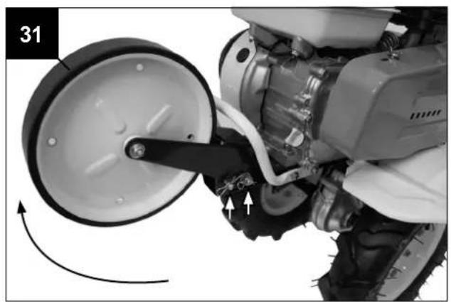
To lock the support wheel in the transport position (Fig.32):
- Two holes (3a + 3b) must be brought into conformity,
- Insert pin (3d) and securing it with cotter
- Insert pin (3e) and securing it with locking screw (3f) and the cotter (Fig.3).
After installation, the wheel must look as shown in Fig.3.
To lock the support wheel in the working position (Fig.33+34):
- Loosen the support wheel from the holes (3a) and re-block it in the holes (3c).
After installation, the wheel must look as shown in Fig.33+34.
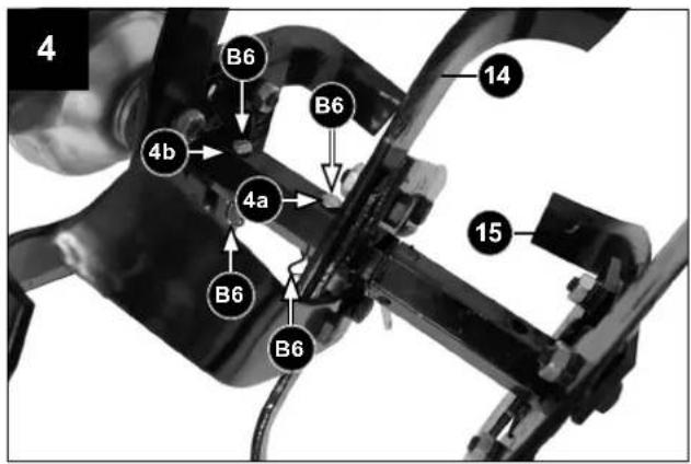
Fitting the Blades (Fig.3-5)
Tillage width 800 mm:
The toolholder (3g) has a hexagonal cross-section to enable quick installation of the blades (14).
1) Grease the toolholder (3g) and observe the alignment of the mounting hole (3h) when installing the blades (14) (Fig.3).
2) Insert the pin (B6, Fig.4) into the opening and secure it with the cotter.
3) Attach the Milling broadening (15) to the petrol power cultivator and check the perfect alignment of the mounting hole (4a).
4) Insert the pin (B6, Fig.4) into the opening (4a) and secure it with the cotter.
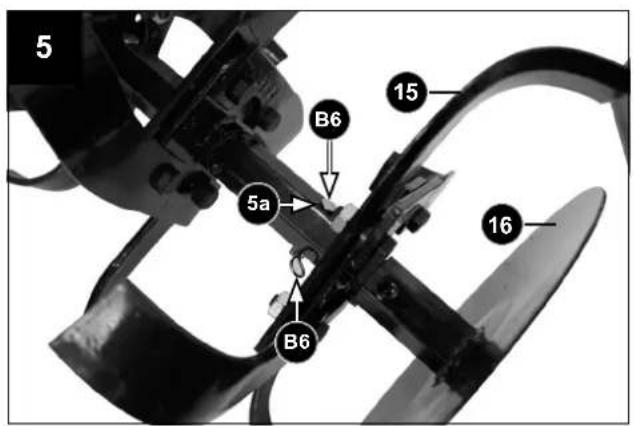
5) Attach the milling protection disc (16) to the milling broadening (15) and check the perfect alignment of the mounting holes (5a).
6) Secure the milling protection disc (16) with the fastening pin large (B6). Then secure the pin with the cotter against loosening.
ATTENTION! If the pin is fitted incorrectly, it may become detached and impair operation of the machine with resulting damage to the machine and operator safety risks!
ATTENTION – When fitting the blades ensure blades cutting edge is always facing into the direction of travel.
The machine can be set to a narrower tillage width (50 cm):
1) Remove the fastening pin large (B6) and disassemble the milling protection disc (16) from the milling broadening (15).
2) Remove the fastening pin large (B6) and disassemble the milling broadening (15) from the blades (14).
3) Attach the milling protection disk (16) to the blades (14) and check the perfect alignment of the two mounting holes.
4) Secure the milling protection disk (16) with the fastening pin large (B6). Then secure the pin with the cotter against loosening.
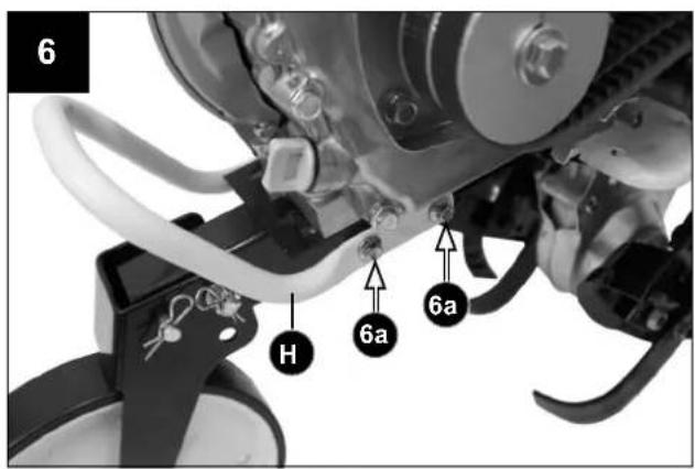
Mounting Front Hand grip (H) (Fig.6)
Remove the hexagonal screws (6a) from the frame by turning counterclockwise.
Attach the front hand grip (H) with the previously disassembled hexagon head screws (6a) as shown in figure 6.
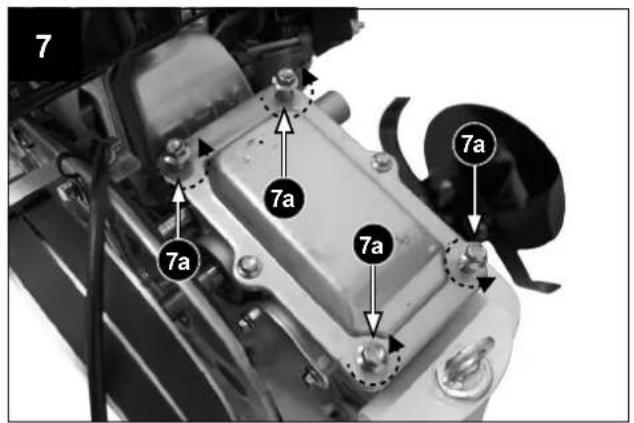
Fitting the steering column (E) (Fig. 7-12)
To install the steering column (E) proceed as follows:
- Loosen the 4 screws (7a) (Fig. 7).
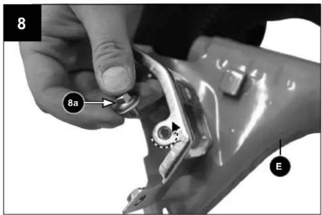
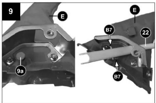
- Loosen screw (8a) and remove them (Fig. 8). Attention! Insert the pin (9a) of the steering column (E) into the gear selector lever (22) (see Fig.9).
- The hole of the gear selector lever (22) and the hole of the steering column pin (9a) must be brought into conformity and the gear selector lever must be locked by using the fastening pin small (B7) and the split pin (see Fig.9).
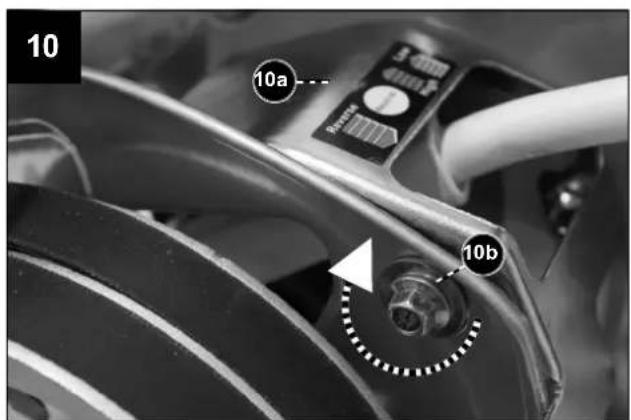
- Fit the cover (10a) of the gear selector lever with screw (10b) (Fig.10).
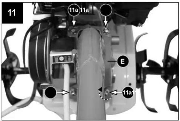
- Mount the steering column (E) and fix it with the 4 screws (11a) (see Fig. 11).
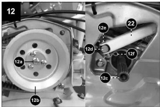
- Loosen and remove the hexagonal screw (12a) by turning it counterclockwise. Hold the support wheel (12b) at the same time (Fig. 12).
- Pull the support wheel (12b) from the shaft (12c) (Fig. 12).
- Subsequently the lower hole at the gear selector lever (22) must be brought into conformity with the hole at the pin (12d) and locked by using the fastening pin (12e) and the split pin (12f) as shown in Fig. 12.
- Insert the support wheel (12b) onto the shaft (12c) (Fig. 12). Observe the correct course of the drive belts!
- Secure the support wheel (12b) with the hexagonal screw (12a) by turning it clockwise. Hold the support wheel (12b) at the same time (Fig. 12).
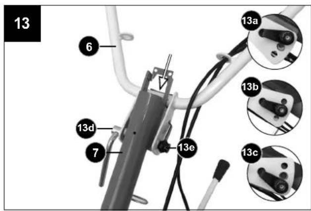
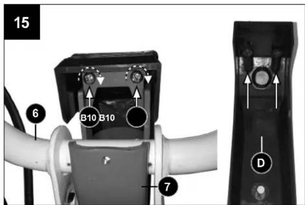
Assembling the handlebar (6) (Fig. 13-15)
Position the handlebar (6) in the seat of steering column (7) as shown in figure 13. The height of the handlebar (6) can be adjusted to three alternative settings.
13a - High
13b - Middle
13c - Low
Lock the handlebar with the special screw (13d) and bracket (13e) if the required height is set.
ATTENTION!
Make sure you insert the hooked end of bracket (13e) in hole of the handlebar (6).
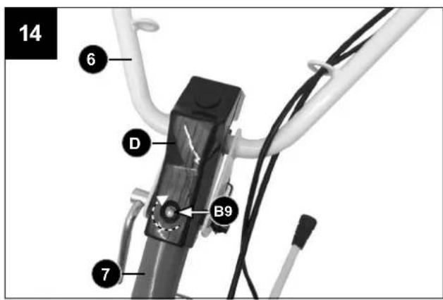
Fasten the cover of the handlebar fixing (D) by using the self-tapping philips screws (B10) and the screw (B9) (see Figs. 14 + 15).
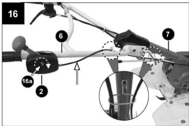
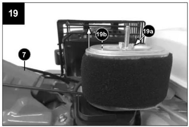
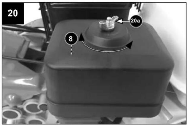
Mounting of the throttle trigger (2) (Fig. 16-20)
Mount the throttle trigger (2) to the handlebar (6) using screw (16a) and nut (Fig.16).
Remove the wing screw (20a) by loosening it counter-clockwise (Fig. 20).
Remove the air filter cover (8) by lifting.
Remove the wing screw (19a) by loosening it counter-clockwise (Fig.19).
Remove the air filter (19b by lifting.
Fix all control cables as shown in figure 16.
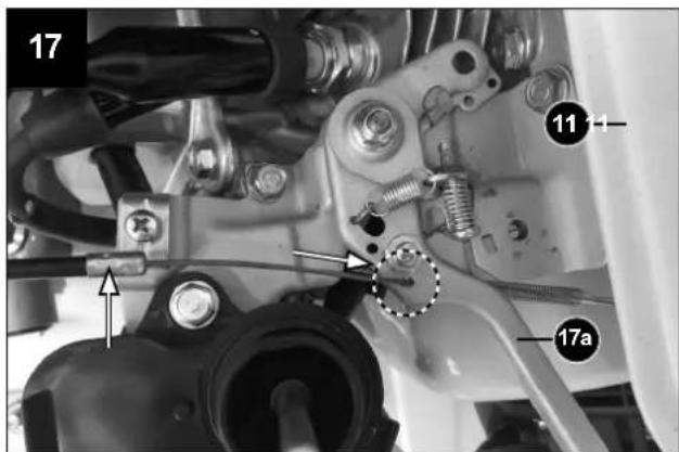
Insert the end of the throttle lever cable into the opening at the lever (17a) (Fig.17).
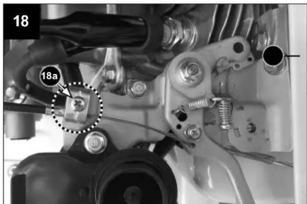
Fit the throttle lever cable with the clamp (18a) as shown in figure 18.
Install air filter (19b) and cover air filter (8) in reverse order.
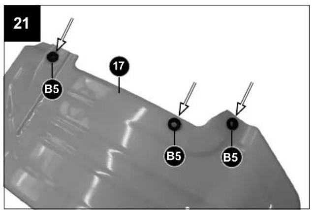
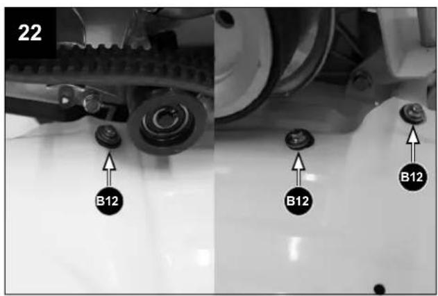
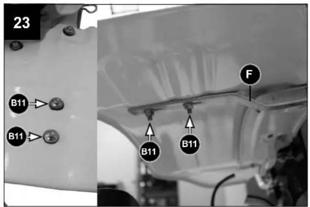
Mounting of the Milling protection housing (17) (Fig. 21-23)
• Fix the rubber rings (B5) accordingly fig. 21
- Attach the milling protection housing (17) with the appropriate screws, washers and nuts (B12) (see Fig. 22).
- Attach the cross connector (F) with the appropriate screws, washers and nuts (B11) (see Fig. 23).
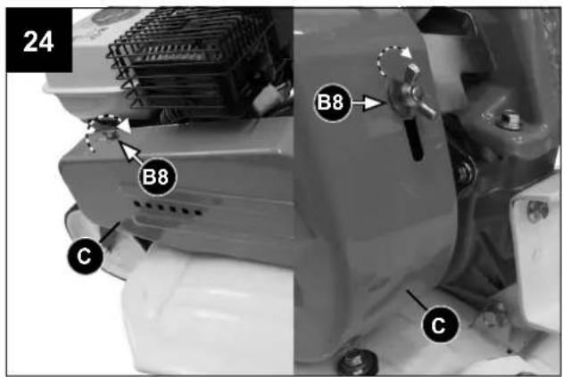
Installing the belt cover (C) (Fig. 24)
- Fix the belt cover (C) with the wing screws (B8) as shown in fig. 24.
⚠️ ATTENTION! The protective housing must be installed!
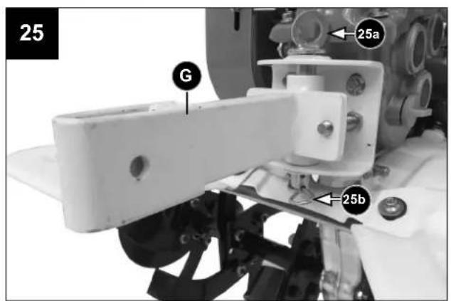
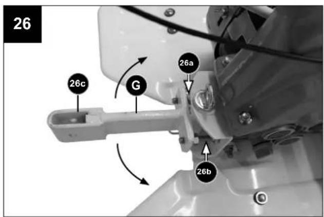
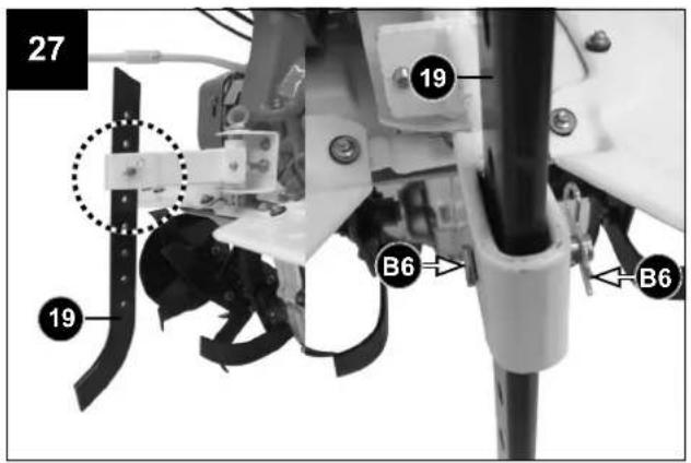
Jackleg / Working depth regulator (19)
- Attach the pick-up point for the jackleg (G) with pin (25a) and split pin (25b) as shown in fig. 25.
- Adjust the desired side position of the jackleg with the adjusting screws 26A and 26B.
- Insert the jackleg (19) into the opening (26c) at the pick-up point (G) (Fig.26) and secure it with the fastening pin and the split pin (B6) (Fig. 27). The depth of the jackleg can be adjusted in various positions.
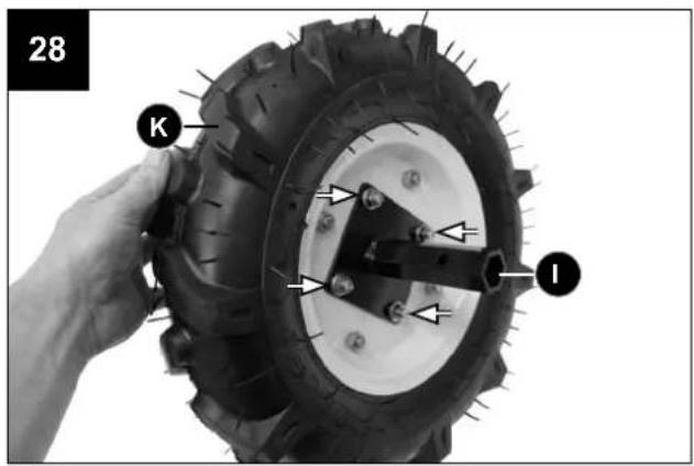
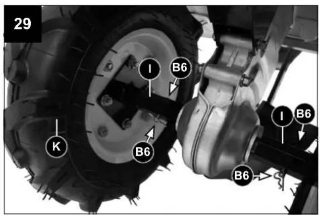
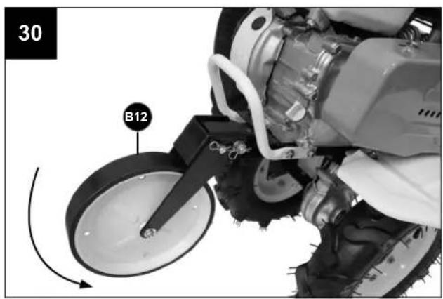
Plow function (Fig. 8/29/32)
Fasten the wheel mountings (I) as shown in fig. 28.
- Grease the tool shaft (3g) and pay attention to the alignment of the mounting hole (3i) (Fig. 3) when installing the wheels (K).
1) Insert the fastening pins large (B6) into the openings and secure them with the split pins.
2) Attach the plow (J) to the desired height using a fastening pin and split pin (B6) as shown in fig. 32.
Adding engine oil
Check the engine oil lever.
Failure to fill engine sump with oil before starting engine will result in permanent damage and void engine warranty (see Engine operator's manual).
Adding transmission oil
Check the transmission oil level.
The gearbox can be permanently damaged and the gearbox warranty will be extinguished if the gearbox is not filled with oil before starting (see chapter "Maintenance & cleaning").
Refueling
⚠ WARNING! Always wear protective gloves when performing maintenance.
This product is powered by a 4 stroke engine.
Store unleaded gasoline in a clean container approved for gasoline.
Recommended fuel:
This engine is certified to operate on unleaded gasoline intended for automotive use with an octane rating of 91 or higher.
Never use stale or contaminated gasoline or an oil/gasoline mixture. Avoid getting dirt or water in the fuel tank.
⚠ WARNING! Follow safety instruction for fuel handling. Always shut off engine before fuelling. Never add fuel to a machine with a running or hot engine. Move at least 3 m from refuelling site before starting engine. DO NOT SMOKE!
- Clean surface around fuel cap to prevent contamination.
- Loosen fuel cap slowly.
- Carefully pour fuel into the tank. Avoid spillage.
- Prior to replacing the fuel cap, clean and inspect the gasket.
- Immediately replace fuel cap and hand tighten. Wipe up any fuel spillage.
⚠ WARNING! Check for fuel leaks, if any are found, correct before use. Contact a Servicing Dealer if necessary.
8. Function
Clutch lever (3)
The forward movement of the blades is carried out by pulling the lever upwards. The machine is stopped by releasing it.
Throttle trigger (2)
It controls the motor speed. Pulling the throttle lever in the directions shown makes the engine run faster or slower.
Jackleg / Working depth regulator (19)
It's for setup of the working depth. The jackleg supports the operator in the direction and speed regulation of the ground hook.
By lowering the depth setting the ground hook would be braked and the working depth would be increased. By lift-up the depth setting, the speed is faster and the working depth would be reduced.
9. Operation
9.1 Adding fuel
Fill the fuel tank as instructed in the separate engine manual.
9.2 Check-up before starting work
Adjusting the clutch (Fig.1)
⚠️ CAUTION! THE POWER CULTIVATOR MUST NOT ROTATE AT IDLE SPEED.
Serious injuries may occur when the cutting tool rotates at idle speed.
⚠️ ATTENTION! Make adjustments on the clutch only by authorized personnel!
Loosen the lock screw (1b).
To adjust the clutch, turn the adjusting screw screw (1a) in the appropriate direction:
- Counterclockwise to increase the tension of the clutch cable,
- Clockwise to reduce the tension of the clutch cable.
The tension of the clutch cable is sufficient as soon as the clutch lever (3) engages into the locking clutch lever (4) when released.
⚠️ ATTENTION! Do not over-tighten the clutch!
After adjustment, tighten the lock screw (1b).
Damage to the clutch can cause the blades to rotate at idle speed. This increases the risk of injury due to loss of controllability and contact with the cutting tool.
9.3 Start the engine
⚠️ ATTENTION! When starting the engine, never pull the clutch lever (3). Pulling the clutch lever (3) will accelerate the engine, thereby rotating the machine's milling tools with the risk of accidents or injuries. Never wrap the starter cord around your hand.
⚠️ CAUTION! You must be in the hatched area at starting the machine.

- Set the throttle lever (2) to position,
- Set the ON / OFF switch (5) to the "ON" position.
- Set the fuel tap (20) to the "ON" position.
- Set the gear selector lever (22) to the "Neutral" position
Operating elements
To actuate the clutch lever (3), release it by pressing the lock (4).
⚠️ CAUTION! To protect against premature wear of the V-belts, pull the clutch lever completely.
Change the gear
△ ATTENTION! Always release the clutch lever (3) before changing the gear and set the throttle lever (2) to minimum speed
Cold start
- Set the Choke lever (21) against the position of, |
- Adjust the throttle lever (2) in the middle position.
- Pull the start lever (18) several times slowly so that fuel can flow into the carburettor of the engine. Then hold the start lever (18) firmly and pull out the rope a little, until you can feel a resistance. Then quickly pull out the start lever (18) without any interruptions and return it slowly back again. Do not allow the start lever (18) to snap back. If necessary, pull the start lever (18) several times until the engine starts.
- Run the engine for several seconds to get warm. Then change the choke lever (21) slowly to the position „N“
- Adjust the required gear with the gear selection lever (22).
- Adjust the throttle lever (2) to the desired speed.
- Grasp the two handles (1) with both hands. Release the locking clutch lever (4) by pressing and pull the clutch lever (3) upwards. As a result, the blades (14) are started and the power cultivator moves forward.
Warm start
If you would restart an engine that is already warm of an earlier use, normally the choke lever (21) must not be operated.
- Adjust the throttle lever (2) in the middle position.
- Hold the start lever (18) firmly and pull out the rope a little, until you can feel a resistance. Then quickly pull out the start lever (18) without any interruptions and return it slowly back again. Do not allow the start lever (18) to snap back.
- Adjust the required gear with the gear selection lever (22).
- Adjust the throttle lever (2) to the desired speed.
- Grasp the two handles (1) with both hands. Release the locking clutch lever (4) by pressing and pull the clutch lever (3) upwards. As a result, the blades (14) are started and the power cultivator moves forward.
High Altitude Operation
At high altitude, the standard carburettor air-fuel mixture will be excessively rich. Performance will decrease, and fuel consumption will increase.
High altitude performance can be improved by specific modifications to the carburetor (1e). If you always operate the engine at altitudes higher than 1.500 m above sea level, let your authorized dealer perform these carburet-tor modifications.
Even with suitable carburettor (1e) setting, engine horse power will decrease approximately 3.5% for each 300 m increase in altitude. The effect of altitude on the horse power will be greater than this if no carburettor modification is made.
⚠ CAUTION! Operation of the engine at an altitude lower than the carburettor is jetted for may result in reduced performance, overheating, and serious engine damage caused by an excessively lean air-/fuel mixture.
Initial start-up of the motor
The engine reaches maximum power after the first 5-8 hours of activity.
During this period of breaking-in do not make the machine function idly at full throttle, to avoid excessive functioning stress.
Startup problems (too much fuel inside the combustion chamber)
If the engine has not started after 10 start attempts, too much fuel may have entered the combustion chamber. Flooded engines can be cleared of excess fuel by following the warm engine starting procedure listed above. Ensure the ON-/OFF switch (5) is in the „ON“ position. Starting could require pulling the starter rope handle (18) many times depending on how badly the unit is flooded.
- Set the ON-/OFF switch (5) to the position „OFF“ (STOPP).
- Lift up the ignition cable (18a) (Fig.18).
- Insert a suitable tool into the socket (18b) of the spark plug (18c).
- Unscrew the spark plug (18c) and dry.
- Set the throttle lever (2) to position,
- Pull out the start lever (18) several times to release the carburetor chamber.
- Reinstall spark plug (18c) and ignition cable (18a)
- Set the ON-/OFF switch (5) to position „ON“ (Start position).
- Set the Choke-lever (21) to position, |, even when the engine is cold.
- Adjust the throttle lever (2) in the center position.
- Hold the start lever (18) firmly and pull out the rope a little, until you can feel a resistance. Then quickly pull out the start lever (18) without any interruptions and return it slowly back again. Do not allow the start lever (18) to snap back.
9.4 Idle speed
Set throttle control lever (2) to its „position to reduce stress on the engine when tilling is not being performed. Lowering the engine speed to idle the engine will help extend the life of the engine, as well as conserve fuel and reduce the noise level of the machine.
9.5 Gear selection
Switching between forward and reverse:
Press the clutch lever (3) to move the power cultivator forward. Release the clutch lever (3). Set the throttle lever (2) to the „position. Adjust the required gear with the gear selection lever (22). Adjust the throttle lever (2) to the desired speed. Grasp the two hand grips (1) with both hands. Release the locking clutch lever (4) by pressing it and pull the clutch lever (3) upwards.
9.6 Stop engine
Move the clutch lever (3) to the starting position to stop the blades.
Make sure that the locking clutch lever (4) engages.
To stop the engine, set the throttle lever (2) to the „” position and the ON-/OFF switch (5) to position „OFF“. Then set the gear selector lever (22) to position „Neutral“.
⚠️ ATTENTION! - With the engine is switched OFF, set the gear selector lever to the „High“ position for safety function as a parking brake (on slopes).
If the „OFF" position of the ON-/ OFF switch (5) does not work, set the choke-lever (21) to the „I” position, to stop the engine. Set the fuel tap (20) against to the „E” position, to stop the engine.
△ ATTENTION! Do not set the choke lever (21) against the „|” position to stop the engine. This can damage the engine.
9.7 Operating speed
Normal operating speed:
- Set the throttle lever (2) to "High" for best results.
Cultivation:
- The throttle lever (2) should be adjusted to the step speed with forward movement.
10. Working instructions
10.1 Depth regulation
Besides depth regulator rod setting, variation of pressure on the handles also helps further control of tilling depth and travel speed. A downward pressure on the handles will reduce the tilling depth and increase the forward speed. An upward pressure on the handles will increase the working depth and reduce the forward speed.
10.2 Tiling
Tilling is digging in, turning over and breaking up garden soil and preparing a seedbed for planting. Best tilling depth is 100 mm to 150 mm. A tiller will also clear the soil of unwanted vegetation. The decomposition of this vegetation matter enriches the soil.
Avoid tilling soil that is too dry as it will pulverize and produce a dust that will not hold water
- Water a few days before tilling.
Also, tilling soil that is too wet will produce unsatisfactory clods. - Wait a day or two after heavy rain for the soil to dry.
Better growth will be obtained if an area is tilled properly and used soon after tilling to preserve the moisture content.
The type of soil and working conditions will determine the actual setting of the tilling depth. In some soils, the desired depth is reached by first passing over garden. In other soils, the desired depth is obtained by going over the garden two or three times. In later case, the depth regulator rod should be lowered before each succeeding pass over the garden.
Passes should be made across the length and width of the garden alternately. Do not try to dig too deeply in the first pass. If the machine jumps or bucks, allow the unit to move forward at a lightly faster rate.
If the tiller stops forward motion and tries to dig in one spot, rock the handles from side to side to start it moving forward again.
Rocks which are turned up should be removed from the garden area.
10.3 Cultivating
Cultivating is loosening or digging around growing plants to disrupt weeds and aerate soil. Less than 50 mm depth is always desirable.
11. Maintenance & Cleaning
Cleaning the machine
⚠️ ATTENTION! - If using compressed air to clean the machine, wear appropriate eye protection and a dust mask.
Keeping your tiller in top running condition will prolong its life, and help you obtain optimum performance whenever you wish to till your garden.
Cleaning blades / tools (14)
Clean the tiller underside of the milling protection housing (17) after each use. The dirt washes off tines easier if rinsed off immediately instead of after it dries.
- Turn off engine. Engine must be cool.
- The ON-/OFF switch (5) to position „OFF“ and disconnect the ignition cable (18a) from the spark plug (18c).
- Remove all vegetation, string, wire, and other materials that may have accumulated to the axle between the inside set of tines and the seal on the transmission housing.
Checking the clutch
As clutch wears out, the same lever could have a wider opening, being so uneasy to use. This means that it is necessary to adjust the cable, setting clutch lever on its original position acting on the adjustment device and on counternut.
- Always towel dry the tiller afterwards and apply a light coat of oil or silicone to prevent rusting or water damage.
- Replace spark plug wire.
ATTENTION! Never use a “pressure washer” to clean your tiller. Water can penetrate tight areas of the tiller and its transmission case and cause damage to spindles, gears, bearings, or the engine. The use of pressure washers will result in shortened life and reduce serviceability.
⚠️ CAUTION! The muffler and other parts of the engine (e.g. fins of the cylinder, spark plug) become hot during operation and remain hot for a while after stopping the engine. To reduce risk of burns do not touch the muffler and other parts while they are hot.
Adjusting the clutch
⚠️ ATTENTION! The machine must not start to rotate until the clutch has been fully actuated.
This is achieved by adjusting the adjusting screws of the clutch. In addition, the clutch lever must start the machine first after max. 8 mm. If the settings are not sufficient to meet these conditions (for example, if the adjusting screw has been screwed up to the end of the thread), please contact an authorized service center.
Blades / Tools
⚠ CAUTION! Never repair damaged tilling attachments by welding, straightening or modifying the blades. This may cause parts of the cutting tool to come off and result in serious or fatal injuries.
Lubrication (Fig. 9)
Remove the blades / tools (14) to lubricate the shafts at least once a season.
Oil change
NOTE: Please dispose of used motor oil in a manner that is compatible with the environment. We suggest you take it in a sealed container to your local service station for reclamation. Do not throw it in the trash, pour it on the ground, or down a drain.
Engine oil
CAUTION:
Operating the engine with a low oil level will result in serious engine damage.
(See engine manual)
Transmission oil
The gearbox is filled with transmission oil by factory and sealed. At the beginning of each season, make sure that the interior of the gearbox is adequately lubricated.
- Check gearbox oil level every 50 hours of operation.
-
Allow the transmission to cool down before refilling with transmission oil.
• After every 100 hours of operation it is necessary to change the transmission oil: -
Check that the machine is in the horizontal position
- Open the closure (1g) by turning it and after the closure (1f) (Fig.1).
- Let the oil drain out of the gearbox until it is completely emptied.
- Close the closure (1f).
- Fill gearbox with SAE 15W-40 oil up to level (Fig.1)
- Close the closure (1g).
Do not add too much transmission oil. Too much transmission oil can create an overpressure that can damage the seals.
Engine Maintenance
Follow the instructions in the engine manual!
Extra maintenance advisable
It is advisable to inspect the machine by a specialized technician at an authorized service network at the end of season, if used intensively, and every two years if with normal use.
Any unauthorized changes and/or use of non-original replacement parts may result in serious injury or death to the operator or third parties.
12. Storage
If the cultivator will not be used for a period longer than 30 days, follow the steps below to prepare your tiller for storage.
- Drain the fuel tank completely. Stored fuel containing ethanol or MTBE can start to go stale in 30 days. Stale fuel has a high plastic content and can clog the carburetor and restrict fuel flow.
- Start the engine and allow it to run until it stops. This ensures no fuel is left in the carburetor. Run the engine until it stops. This helps prevent plastic deposits from forming inside the carburetor and possible engine damage.
- While the engine is still warm, drain the oil from the engine. Refill with fresh oil of the grade recommended in the Engine Manual.
- Allow the engine to cool. Remove the spark plug (18c) and put 30 ml of high quality motor oil into the cylinder. Pull the start lever (18) slowly to distribute the oil. Replace the spark plug (18c).
⚠️ ATTENTION! Remove the spark plug (18c) and drain all of the oil from the cylinder before attempting to start the unit after storage.
- Use clean cloths to clean off the outside of the tiller and to keep the air vents free of obstructions.
⚠️ ATTENTION! Do not use strong detergents or petroleum based cleaners when cleaning plastic parts. Chemicals can damage plastics.
-
Inspect for any loose or damaged parts. Repair or replace damaged parts and tighten loose screws, nuts or bolts.
-
Remove the blades. Clean and apply oil to the tines and tine shafts (3g) to prevent rusting. Mount the tines onto the tine shafts (3g).
- Coat the wheel axles lightly with oil. Oil the throttle cables and all visible moving parts. Do not remove the engine cover.
- Storage with retracted handlebars: Loosen the special screw (13d) which secures the up- per handlebar (6) with the lower steering column (7). Gently lower the upper handlebar (6) downwards. Make sure that the control cables are not pinched or kinked. Tighten the special screw (13d).
- Store your tiller in upright position in a clean, dry building that has good ventilation.
⚠️ ATTENTION! Do not store tiller with fuel in a non-ventilated area where fuel fumes may reach flame, sparks, pilot lights or any ignition sources. Use only approved fuel containers.
13. Transport
Transportation by pushing Install the wheels as described in the chapter "Plowing function".
Start the engine and gently accelerate. Machine moves slowly forwards.
14. Disposal and recycling
The equipment is supplied in packaging to prevent it from being damaged in transit. The raw materials in this packaging can be reused or recycled.
The equipment and its accessories are made of various types of material, such as metal and plastic. Defective components must be disposed of as special waste. Ask your dealer or your local council.
15. Troubleshooting
⚠ ATTENTION! Before carrying out any tests recommended in the following table, always turn off the unit and disconnect the spark plug, unless the operation of the unit is expressly required.
If all possible causes have been checked but the problem has not been solved, please contact an authorized service center. If a problem does not appear in this table, please contact an authorized service center.
SERVICE-INFORMATIONS
Please note that the following parts of this product are subject to normal or natural wear and that the following parts are therefore also required for use as consumables.
Wear parts* spark plug, blades / tools, starter cable, all operating fluids/fuels
* Not necessarily included in the scope of delivery!
ATTENTION!
Note for the case of sending the equipment to a customer service center:
For safety reasons, ensure that the unit is free of oil and gasoline!
| Problem Cause Remedy | ||
| Engine fails to start. Spark plug wire disconnected. | Plug wire disconnected. | Attach spark plug wire securely to spark plug. Fill with clean, fresh gasoline. |
| Out of fuel or stale fuel. | Move throttle control lever to start position. | |
| Throttle control lever not in correct starting position. | Chock must be positioned at “ nor a cold start. | |
| Choke not in „N Position. | Clean the fuel line. | |
| Blocked fuel line. | Clean, adjust gap, or replace. | |
| Fouled spark plug. | Wait a few minutes to restart, but do not prime. | |
| Engine flooding. | Tine clutch control lever must be released to neutral to start the engine. | |
| Tine clutch control not in initial position. | ON-/OFF switch at position “ ON ” | |
| ON-/OFF switch at position “ OFF ” | ||
| Engine runs erratically. Spark plug wire loose. | Unit running on CHOKE. | Connect and tighten spark plug wire. |
| Blocked fuel line or stale fuel. | Move choke lever contrary to position “ N Clean fuel line. Fill tank with clean, fresh gasoline. | |
| Vent plugged. | Clear vent. | |
| Water or dirt in fuel system. | Drain fuel tank. Refill with fresh fuel. | |
| Dirty air cleaner. | Clean or replace air cleaner. | |
| Improper carburetor adjustment. | Refer to Engine Manual. | |
| Engine overheats. Engine oil level low. | Level low. | Fill crankcase with proper oil. |
| Dirty air cleaner. | Clean air cleaner. | |
| Air flow restricted. | Remove blower housing and clean. | |
| Carburetor not adjusted properly. | Refer to Engine Manual. | |
| Engine will not stop when throttle control is positioned at „”, or engine speed does not increase properly when throttle control is adjusted. | Debris interfering with throttle linkage. | Clean dirt and debris. |
| Improper throttle linkage adjustment. | Refer to Engine Manual to check and adjust throttle linkage. | |
| Tiller moves forward during starting. | Tine clutch control not in neutral position. | Tine clutch control lever must be released to neutral to start the engine. |
| Tiller is difficult to control when tilling (machine jumps or lurches forward). | Improper tilling depth setting. | Raise the tines for shallower tilling by raising the depth regulator rod. |
| Too high engine speed on hard ground. | Set the throttle lever at lower speed. | |
| Tines do not engage. Foreign object lodged in tines. | Tine clevis pin(s) missing. | Stop tiller completely, check and discard foreign object. |
| Belt worn and/or stretched. | Replace tine clevis pin(s). | |
| Pulley and idler not in correct adjustment. | Replace belt. Contact dealer. | |
Günzburger Straße 69
D-89335 Ichenhausen
Cher client,
Noise: measured L_wA = xx dB(A) ; guaranteed L_wA = xx dB(A) Notified Body: Notified Body No.:
X 2004/26/EC
Emission. No: e11*97/68SA*2012/46*2949*00(II)
Standard references: EN 709; EN ISO 14982
Subject to change without notice
Documents registrar:
Stefan Hartinger
Günzburger Str. 69, D-89335 Ichenhausen
Garantie DE
Apparent defects must be notified within 8 days from the receipt of the goods. Otherwise, the buyerls rights of claim due to such defects are invalidated. We guarantee for our machines in case of proper treatment for the time of the statutory warranty period from delivery in such a way that we replace any machine part free of charge which provably becomes unusable due to faulty material or defects of fabrication within such period of time. With respect to parts not
manufactured by us we only warrant insofar as we are entitled to warranty claims against the upstream suppliers. The costs for the installation of the new parts shall be borne by the buyer. The cancellation of sale or the reduction of purchase price as well as any other claims for damages shall be excluded.