H-7619 - Flat screen mount Uline - Free user manual and instructions
Find the device manual for free H-7619 Uline in PDF.

User questions about H-7619 Uline
0 question about this device. Answer the ones you know or ask your own.
Ask a new question about this device
Download the instructions for your Flat screen mount in PDF format for free! Find your manual H-7619 - Uline and take your electronic device back in hand. On this page are published all the documents necessary for the use of your device. H-7619 by Uline.
USER MANUAL H-7619 Uline
Phillips Screwdriver
3x3Allen Wrench
4 x 4 Allen Wrench (F)
5 x 5 Allen Wrench (G)
6 x 6 Allen Wrench

(all included)
Two Person Assembly Required
NOTE: Make sure the monitors have a VESA hole pattern of 75 × 75 ~mm or 100 × 100 ~mm . (See Figure 1)

NOTE: If the monitors are attached to fixed bases, remove monitors from bases.

CAUTION! Be careful not to scratch the monitor screen during installation.
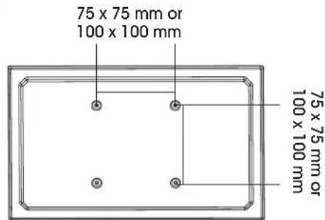
Figure 1
ASSEMBLY
CLAMP MOUNTING
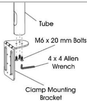
1
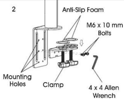
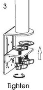
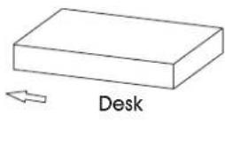
Figure 2

NOTE: Clamp mount is compatible with desk thickness of 3/4 - 3%^7 .
- Attach clamp mounting bracket (5) to bottom of tube (4) using M6 x 20 mm bolts (C) and 4 x 4 Allen wrench (F). (See Figure 2)

NOTE: Opening near bottom of tube is for cable management. Make sure this opening is aligned with back of clamp mounting bracket.
- Apply anti-slip foam (6) to rings on clamp (7). Select the appropriate mounting holes based on thickness of the desk. Attach clamp (7) to the clamp mounting bracket (5) using M6 x 10 mm bolts (D) and 4 x 4 Allen wrench (F).
- Place clamp mounting bracket and clamp over desk and fully tighten knobs.
GROMMET MOUNTING
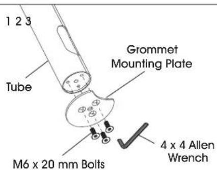

6x6Allen Wrench
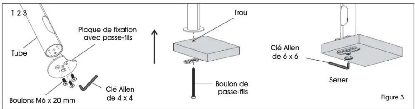
Figure 3

NOTE: For grommet mounting, hole in desk must be 3/8 - 214 .

NOTE: Grommet mount is compatible with desk thickness of 1 - 3^1/2 .
- Attach grommet mounting plate (8) to bottom of tube (4) using M6 x 20 mm bolts (C) and 4 x 4 Allen wrench (F). (See Figure 3)

NOTE: Opening near bottom of tube is for cable management. Make sure this opening is aligned with indent on grommet mounting plate.
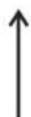
- Thread grommet bolt (10) through bottom support (9). Insert bolt into hole of desk and into center hole in grommet mounting plate (8).
- Fully fighten grommet bolt (10) using 6 × 6 Allen wrench.
ASSEMBLY CONTINUED
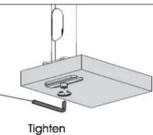
ATTACHING MONITOR ARM
- Place monitor arm (2) over tube (4) and choose desired height of monitor. (See Figure 4)
- Flip lever on monitor arm to lock in place. Using a 3 × 3 Allen wrench, tighten the bolt directly underneath the lever to secure monitor arm.
CAUTION! Make sure lever is tightly locked before attaching monitor.
- Attach cable clips (3) to monitor arm.
ATTACHING MONITOR
123
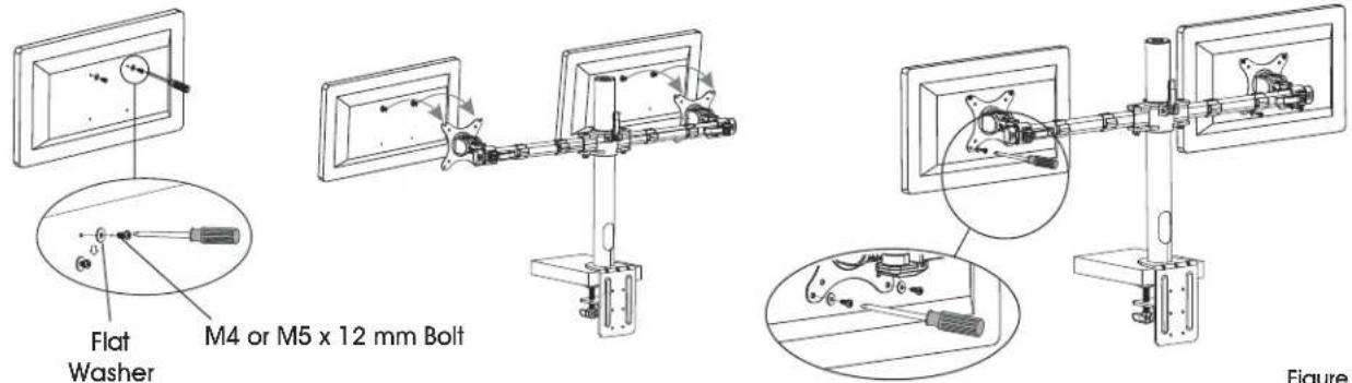
Figure 5

NOTE: Two-person assembly is required for this step.

NOTE: Depending on size of holes, use either M4 x 12 mm bolts (A) or M5 x 12 mm bolts (B). If holes are not deep enough, add flat washers (E) to bolts to ensure a tight fit.
- One person should hold the monitor and align the bolt holes on the back of the monitor with the mounting plate. The second person should insert bolts into the top two holes in the mounting plate and monitor. Loosely tighten both bolts.

NOTE: For 100 × 100 ~mm VESA hole pattern, bolts can be inserted into the top holes in back of monitor and lowered into mounting plate for easier attachment.
- While one person continues to hold the monitor, the second person should insert bolts into the bottom two holes in the mounting plate and monitor. Then, fully tighten all four bolts.

NOTE: Repeat steps to attach second monitor.
ASSEMBLY CONTINUED
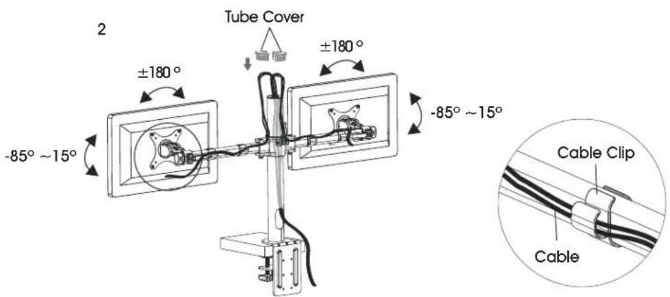
ADJUSTING MONITOR AND CABLE MANAGEMENT
1
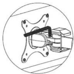
Figure 6
-
If the monitor is difficult to adjust, use a 5 × 5 mm Allen wrench (G) to loosen bolts at hinges of monitor arm and mounting plate as needed. (See Figure 6)
-
Cables can be managed by running them through cable clips on monitor arm and through the openings in tube.
ULINE H-7619
SOPORTE DOBLE PARA MONITORES - ESTÁNDAR
800-295-5510
uline.mx
FIXATION AVEC PASSE-FILS