H-10162 - Flat screen mount Uline - Free user manual and instructions
Find the device manual for free H-10162 Uline in PDF.

User questions about H-10162 Uline
0 question about this device. Answer the ones you know or ask your own.
Ask a new question about this device
Download the instructions for your Flat screen mount in PDF format for free! Find your manual H-10162 - Uline and take your electronic device back in hand. On this page are published all the documents necessary for the use of your device. H-10162 by Uline.
USER MANUAL H-10162 Uline
natural_image
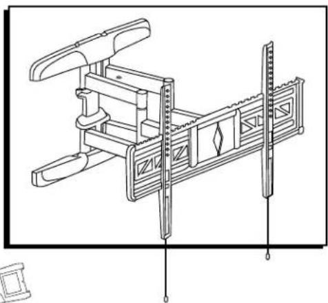
Technical line drawing of a mechanical clamp or bracket assembly (no text or symbols)TOOLS NEEDED
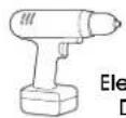
Electric Drill

Phillips Head
Drill Bit
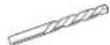
3/16" Drill Bit 3/8" Drill Bit
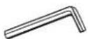
6 x 6 mm Allen Wrench (included)
Tape Measure
Phillips
Screwdriver

Magnetic Level (included)

Box Wrench (included)
Stud Finder

Two-Person Assembly Recommended
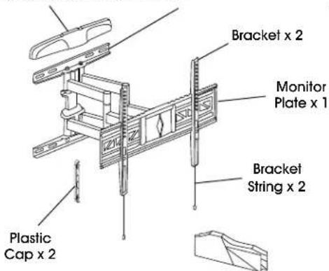
PARTS
Plastic Cover x 2 Wall Plate x 1
text_image
Bracket x 2 Monitor Plate x 1 Bracket String x 2 Plastic Cap x 2Cable Management
Clip A x 4
B1
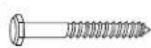
Lag
Screw x 6
B2
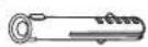
Plastic Anchor x 6
Square Washer x 4


Spacer x 4
B3

Washer x 6
A1

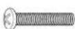
M4 x 12 mm Bolt x 4

M4 x 25 mm Bolt x 4
A2

M5 x 12 mm Bolt x 4

M5 x 25 mm Bolt x 4
A3

M6 x 12 mm Bolt x 4

M6 x 25 mm Bolt x 4
A4
M8 x 25 mm Bolt x 4M8 x 16 mm
INSTALLATION

CAUTION! This product is designed to be installed on solid concrete walls or drywall with wood studs. Before installing, ensure wall will support the combined load of the equipment.

CAUTION! Be careful not to scratch the monitor screen during assembly.
ATTACHING TO WALL
CONCRETE WALL
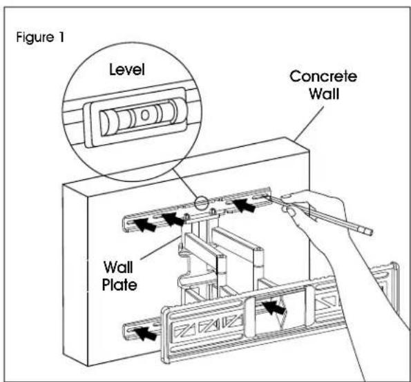
- Align wall plate in desired location. Place level on top of the wall plate to ensure it is leveled correctly. Mark where holes for screws are to be located. (See Figure 1)

NOTE: Mark four hole locations on the top section of wall plate, and two hole locations on the bottom section.
text_image
Figure 1 Level Concrete Wall Wall PlateINSTALLATION CONTINUED
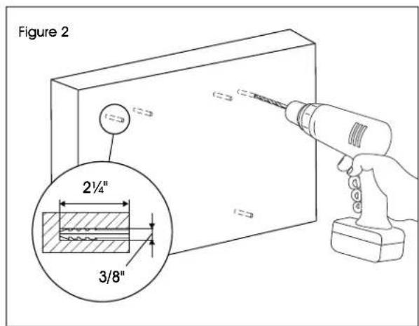
- Drill six 2 ^1/4 " deep holes using 3/8" drill bit. Insert plastic anchors (B2) into pre-drilled holes. (See Figure 2)

NOTE: It is recommended to use a masonry drill bit for concrete walls.
text_image
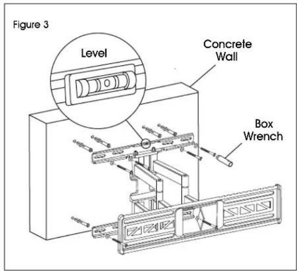
Figure 2 2½" 3/8"- With magnetic level attached, install wall plate using six lag screws (B1) and washers (B3). (See Figure 3)
text_image
Figure 3 Level Concrete Wall Box WrenchDRYWALL

WARNING! If mounting to drywall, wall plate must be properly attached to wood studs behind the wall in order to hold the listed capacity.
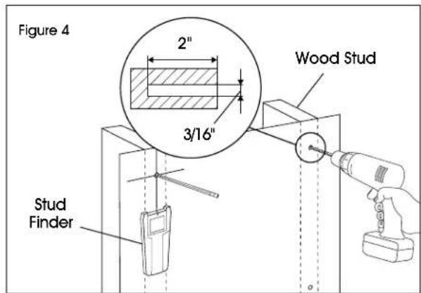
- Using stud finder, locate the studs that will be used for mounting. Studs are commonly spaced 16" center-to-center. At roughly the desired location and height, mark the center of the stud.
-
Align wall plate with studs and move to desired location. Place level on top of the wall plate to ensure it is leveled correctly. Mark where holes for screws are to be located. (See Figure 4)
-
Drill four holes using 3/16" drill bit. (See Figure 4)

NOTE: Two hole locations should be marked on each stud.
text_image
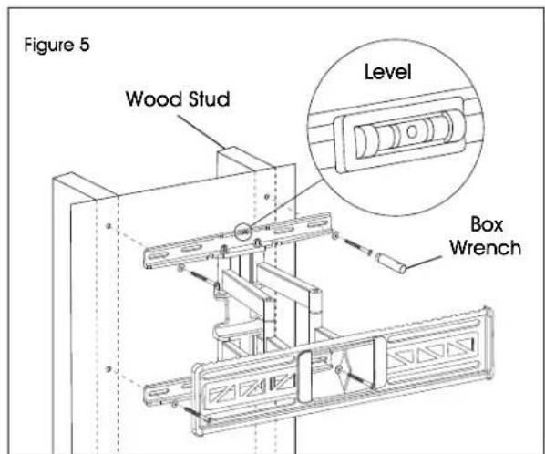
Figure 4 2" 3/16" Wood Stud Stud Finder- With magnetic level attached, install wall plate using four lag screws (B1) and washers (B3). (See Figure 5)
text_image
Figure 5 Wood Stud Level Box WrenchINSTALLATION CONTINUED
ATTACHING BRACKETS TO MONITOR
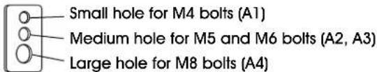
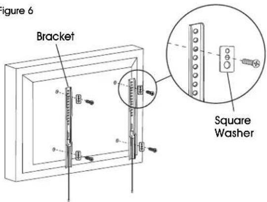
Determine bolt size that is compatible with the monitor. Using the square washers and spacers, install each bracket to the monitor.
SQUARE WASHER
text_image
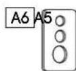
Small hole for M4 bolts (A1) Medium hole for M5 and M6 bolts (A2, A3) Large hole for M8 bolts (A4)
NOTE: For monitors with flat backs, spacers (A5) are not needed. (See Figure 6)
Figure 6
text_image
Figure 6 Bracket Square Washer
NOTE: For monitors with a curved back or obstructions, place spacers (A5) on the side closest to the monitor. (See Figure 7)
Figure 7
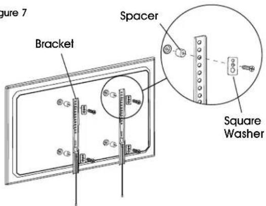
text_image
Figure 7 Bracket Spacer Square WasherCONNECTING BRACKETS TO MONITOR PLATE
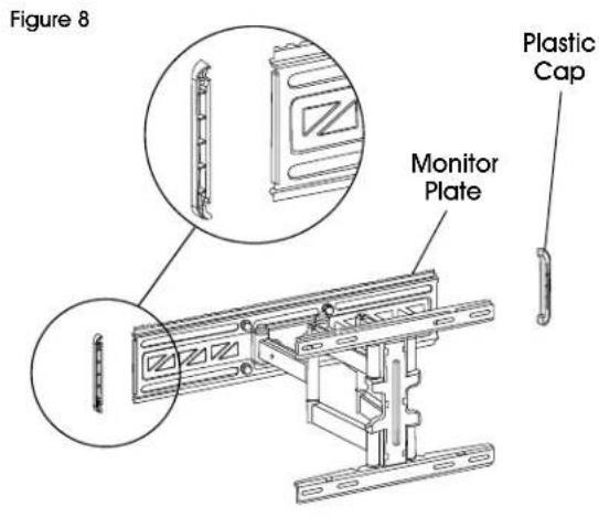
- Place plastic caps over the ends of the monitor plate. (See Figure 8)
text_image
Figure 8 Plastic Cap Monitor Plate- With second person, carefully lift and align brackets on the back of monitor with the monitor plate. Tilt top of monitor toward wall and place the top of the brackets over the monitor plate. Slowly rotate the bottom of the monitor toward wall and clip the bottom of the brackets over monitor plate. This will lock the brackets onto monitor plate.

NOTE: Strings that are used to release the monitor from the mount may be visible after installation. These can be hidden behind the monitor using magnetic tips. (See Figure 9)
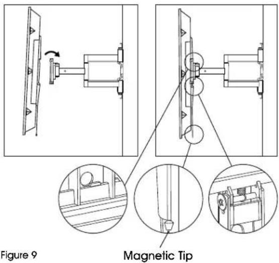
text_image
Figure 9 Magnetic TipINSTALLATION CONTINUED
ADJUSTING MONITOR AND CABLE MANAGEMENT
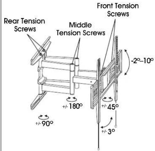
- To increase or decrease the swivel/tilt tension, adjust the rear, middle and front tension screws. (See Figure 10)

NOTE: Rear and middle tension screws have adjustments on the top and bottom of the unit.
- Attach plastic covers to top and bottom of wall plate. (See Figure 10)
- Attach cable management clips to the top and bottom of the wall plate and support bars. Cables can be managed by running them through the clips. (See Figure 10)
Figure 10
text_image
Rear Tension Screws Middle Tension Screws Front Tension Screws -2°-10° +/- 180° +/- 45° +/- 90° +/- 3°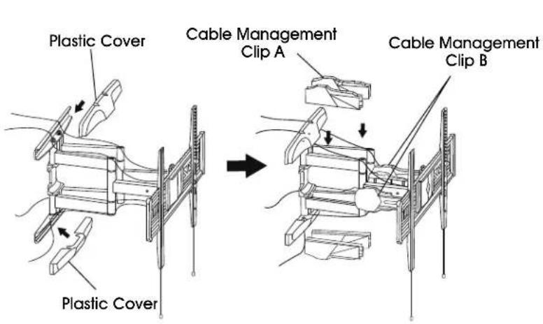
text_image
Plastic Cover Cable Management Clip A Cable Management Clip B Plastic CoverREMOVING THE MONITOR
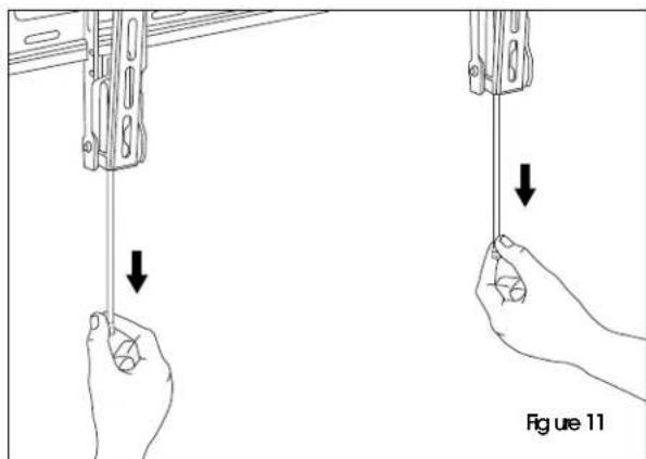
With second person, pull down on the strings attached to the brackets. This will unlock the brackets from the wall plate, and the monitor can be removed. (See Figure 11)
natural_image
Illustration of two hands holding a device with downward arrows indicating motion, labeled 'Figure 11' (no text or symbols on the devices themselves)ULINE H-10162
800-295-5510
uline.mx
SOPORTE DE PARED PARA
PANTALLA – MOVIMIENTO TOTAL DE 32-80"