
H-10161 - Flat screen mount Uline - Free user manual and instructions
Find the device manual for free H-10161 Uline in PDF.

User questions about H-10161 Uline
0 question about this device. Answer the ones you know or ask your own.
Ask a new question about this device
Download the instructions for your Flat screen mount in PDF format for free! Find your manual H-10161 - Uline and take your electronic device back in hand. On this page are published all the documents necessary for the use of your device. H-10161 by Uline.
USER MANUAL H-10161 Uline
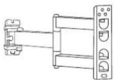
WALL MONITOR MOUNT – 17-50' FULL MOTION
1-800-295-5510
uline.com
natural_image
Technical line drawing of a mechanical assembly with mounting flanges and a vertical rail (no text or symbols)TOOLS NEEDED
Electric Drill

Phillips Head
Drill Bit
3/16" Drill Bit
3/8" Drill Bit
4 x 4 mm Allen Wrench
5 x 5 mm Allen Wrench
(included)
Tape Measure
Phillips
Screwdriver

Magnetic Level (included)
Stud Finder

13 mm Socket

Two-Person Assembly Recommended
PARTS
Adapter x 4
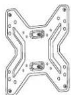
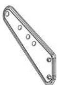
Monitor Plate x 1 Wall Plate x 1


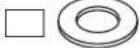
Square Washer x 4
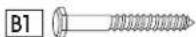
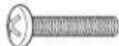
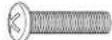
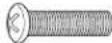
Lag Screw x 3
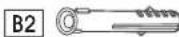
Plastic Anchor x 3
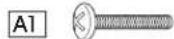

M4 x 20 mm Bolt x 4 M5 x 20 mm Bolt x 4

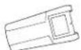
Cable Management
Clip x 1

Spacer x 4
Washer x 3


M6 Nut x 2 M6 x 6 mm
Bolt x 8

M6 x 20 mm Bolt x 4

M8 x 20 mm Bolt x 4
INSTALLATION

CAUTION! This product is designed to be installed on solid concrete walls or drywall with wood studs. Before installing, make sure the wall will support the combined load of the equipment.

CAUTION! Be careful not to scratch the monitor screen during assembly.
ATTACHING TO WALL
CONCRETE WALL
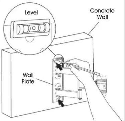
- Align wall plate in desired location. Place level on top of the wall plate to ensure it is leveled correctly. Mark where holes for screws are to be located. (See Figure 1)
Figure 1
text_image
Level Concrete Wall Wall PlateINSTALLATION CONTINUED
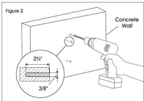
- Drill holes 2 ^3/4 " deep using 3/8" drill bit. Insert plastic anchors (B2) into pre-drilled holes. (See Figure 2)
text_image
Figure 2 Concrete Wall 2¾" 3/8"
NOTE: It is recommended to use a masonry drill bit for concrete walls.
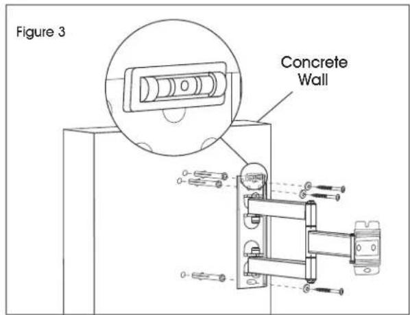
- Keep magnetic level attached to wall plate. Using a drill and 13 mm socket, install wall plate onto wall using lag screws (B1) and washers (B3). (See Figure 3)
text_image
Figure 3 Concrete WallDRYWALL

WARNING! If mounting to drywall, wall plate must be properly attached to wood stud behind the wall in order to hold the listed capacity.
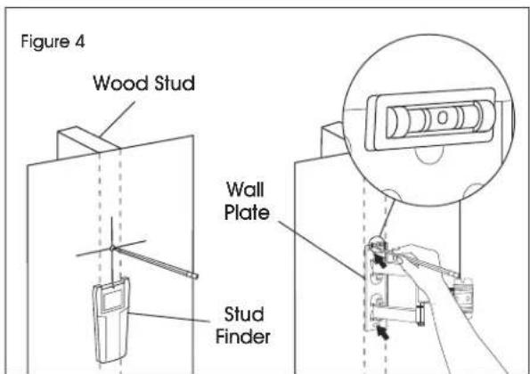
- Using stud finder, locate the stud that will be used for mounting. At roughly the desired location and height, mark the center of the stud. (See Figure 4)
- Align wall plate with stud and move to desired location. Place level on top of the wall plate to ensure it is leveled correctly. Mark where holes for screws are to be located. (See Figure 4)
text_image
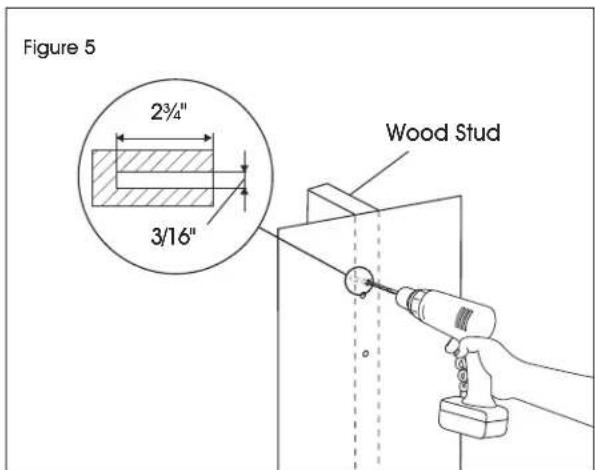
Figure 4 Wood Stud Wall Plate Stud Finder- Drill holes 2 ^3/4 " deep using 3/16" drill bit. (See Figure 5)
text_image
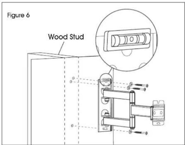
Figure 5 2³/⁴" 3/16" Wood Stud- Keep magnetic level attached to wall plate. Using a drill and 13 mm socket, install wall plate onto wall using lag screws (B1) and washers (B3). (See Figure 6)
text_image
Figure 6 Wood StudINSTALLATION CONTINUED
ATTACHING MONITOR PLATE
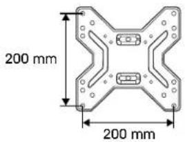
- Determine the hole pattern on the back of the monitor. If the hole pattern is larger than the monitor plate, the monitor adapters must be attached using M6 x 6 mm bolts (B4). (See Figures 7-8)
Figure 7
text_image
200 mm 200 mm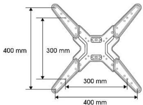
text_image
400 mm 300 mm 300 mm 400 mm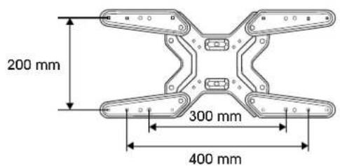
text_image
200 mm 300 mm 400 mmFigure 8
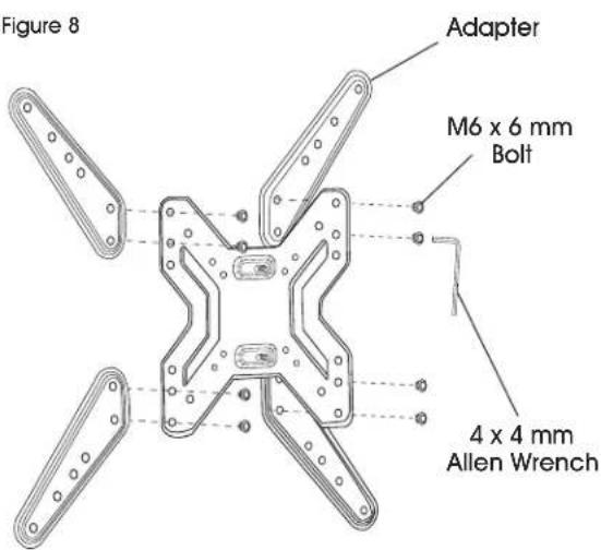
text_image
Figure 8 Adapter M6 x 6 mm Bolt 4 x 4 mm Allen Wrench- Determine bolt size that is compatible with monitor. Using the square washers (A6) and spacers (A5), install the monitor plate to the monitor.
SQUARE WASHER
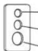
Small hole for M4 screws (A1)
Medium hole for M5 and M6 screws (A2, A3)
Large hole for M8 screws (A4)

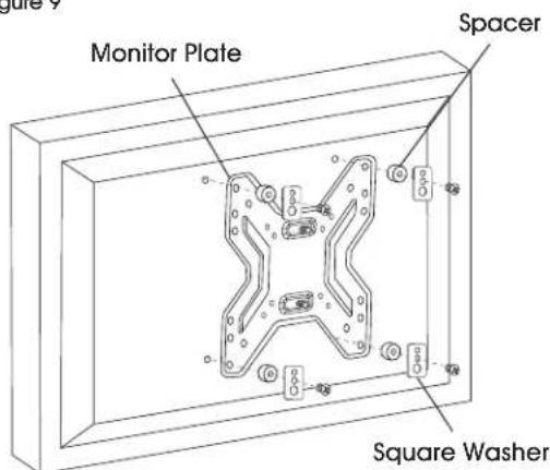
NOTE: For monitors with flat backs, use spacers (A5) on the outside of brackets. (See Figure 9)
Figure 9
text_image
Monitor Plate Spacer Square Washer
NOTE: For monitors with a curved back or obstructions, place spacers (A5) on the side closest to the monitor. (See Figure 10)
Figure 10
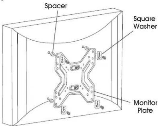
text_image
Spacer Square Washer Monitor PlateINSTALLATION CONTINUED
CONNECTING MONITOR PLATE TO WALL PLATE
- With second person, carefully lift the monitor and align the holes of the monitor plate with the wall plate. While one person continues to hold the monitor, attach the top M6 nut (B4) first, then the bottom M6 nut, to secure the monitor plate to the wall plate. (See Figure 11)
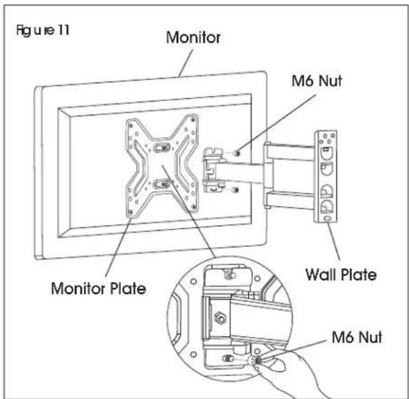
text_image
Figure 11 Monitor M6 Nut Monitor Plate Wall Plate M6 NutADJUSTING MONITOR AND CABLE MANAGEMENT
-
If the monitor needs to be adjusted, use the 5 x 5 mm Allen wrench to loosen and tighten the tension screws. (See Figure 12)
-
Cables can be managed by running them through the cable management clip that attaches to the support bars. (See Figure 12)
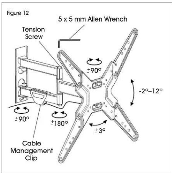
text_image
Figure 12 5 x 5 mm Allen Wrench Tension Screw ±90° ±90° ±180° Cable Management Clip ±3° -2°-12°ULINE H-10161
SOPORTE DE PARED PARA PANTALLA – MOVIMIENTO TOTAL DE 17-50"
natural_image
Technical line drawing of a mechanical assembly with mounting flanges and a vertical rail (no text or symbols)
Cinta de Medir


text_image
Diagrama 2 Pared de Concrete 2¾" 3/8"


