H-7618 - Flat screen mount Uline - Free user manual and instructions
Find the device manual for free H-7618 Uline in PDF.

User questions about H-7618 Uline
0 question about this device. Answer the ones you know or ask your own.
Ask a new question about this device
Download the instructions for your Flat screen mount in PDF format for free! Find your manual H-7618 - Uline and take your electronic device back in hand. On this page are published all the documents necessary for the use of your device. H-7618 by Uline.
USER MANUAL H-7618 Uline
TOOLS NEEDED
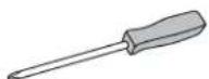
Phillips Screwdriver
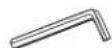
3 x 3 Allen Wrench
4 x 4 Allen Wrench (F)
5 x 5 Allen Wrench (G)
6 x 6 Allen Wrench (all included)

Two Person Assembly Required
natural_image
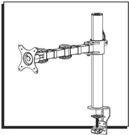
Technical line drawing of a mechanical assembly with no visible text or symbolsPARTS

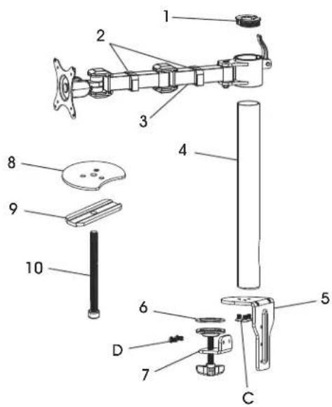
text_image
Exploded view diagram of a mechanical assembly with numbered parts for identification| # DESCRIPTION QTY. | ||
| 1 Tube Cover 2 | ||
| 2 Cable Clip 2 | ||
| 3 Monitor Arm 1 | ||
| 4 Tube 1 | ||
| 5 Clamp Mounting Bracket | 1 | |
| 6 Anti-Slip Foam | 1 | |
| 7 Clamp | 1 | |
| 8 Grommet Mounting Plate | 1 | |
| 9 Bottom Support | 1 | |
| 10 | Grommet Bolt | 1 |
| A M4 x 12 mm Bolt (Not Shown) | 4 | |
| B M5 x 12 mm Bolt (Not Shown) | 4 | |
| C | M6 x 20 mm Bolt | 3 |
| D | M6 x 10 mm Bolt 2 | |
| E Flat Washer (Not Shown) | 8 | |
SETUP

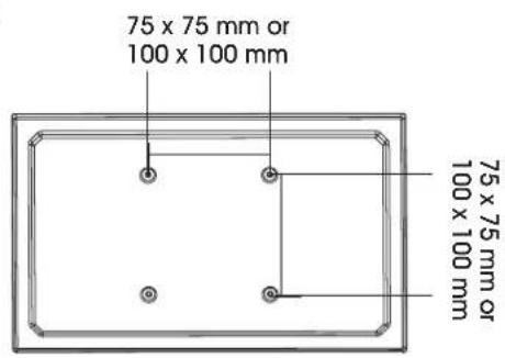
NOTE: Make sure the monitor has a VESA hole pattern of 75 x 75 mm or 100 x 100 mm. (See Figure 1)

NOTE: If the monitor is attached to a fixed base, remove monitor from base.

CAUTION! Be careful not to scratch the monitor screen during installation.
Figure 1
text_image
75 x 75 mm or 100 x 100 mm 75 x 75 mm or 100 x 100 mmASSEMBLY
CLAMP MOUNTING
text_image
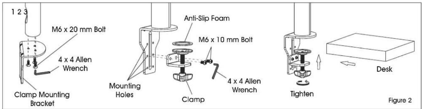
1 2 3 M6 x 20 mm Bolt 4 x 4 Allen Wrench Clamp Mounting Bracket Mounting Holes Anti-Slip Foam M6 x 10 mm Bolt 4 x 4 Allen Wrench Clamp Tighten Desk Figure 2
NOTE: Clamp mount is compatible with desk thickness of 3/4 - 3 ^7/8 ".
- Attach clamp mounting bracket (5) to bottom of tube (4) using M6 x 20 mm bolts (C) and 4 x 4 Allen wrench (F). (See Figure 2)

NOTE: Opening near bottom of tube is for cable management. Make sure opening is aligned with back of clamp mounting bracket.
- Apply anti-slip foam (6) to ring on clamp (7). Select the appropriate mounting holes based on the thickness of the desk. Attach clamp (7) to the clamp mounting bracket (5) using M6 x 10 mm bolts (D) and 4 x 4 Allen wrench (F).
- Place clamp mounting bracket and clamp over desk and fully tighten knob.
GROMMET MOUNTING
text_image
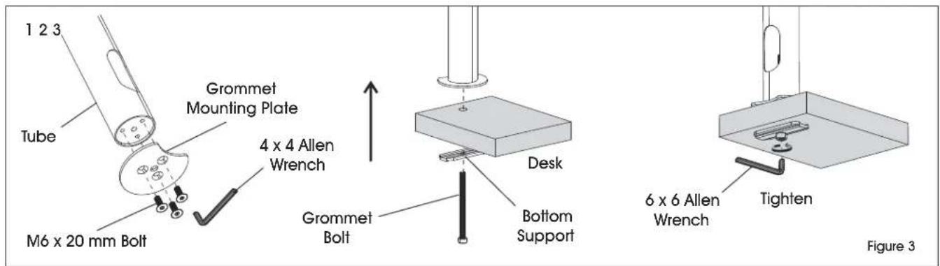
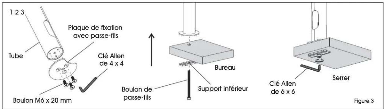
1 2 3 Tube Grommet Mounting Plate 4 x 4 Allen Wrench M6 x 20 mm Bolt Grommet Bolt Desk Bottom Support 6 x 6 Allen Wrench Tighten Figure 3
NOTE: For grommet mounting, hole in desk must be 3/8 - 2^3/4 .

NOTE: Grommet mount is compatible with desk thickness of 1 - 312 .
- Attach grommet mounting plate (8) to bottom of tube (4) using M6 x 20 mm bolts (C) and 4 x 4 Allen wrench (F). (See Figure 3)

NOTE: Opening near bottom of tube is for cable management. Make sure opening is aligned with indent on grommet mounting plate.
- Thread grommet bolt (10) through bottom support (9). Insert bolt into hole of desk and into center hole in grommet mounting plate (8).
- Fully tighten grommet bolt (10) using 6 x 6 Allen wrench.
ASSEMBLY CONTINUED
ATTACHING MONITOR ARM
1
text_image
Desk Allen3 x 3 Allen Wrench
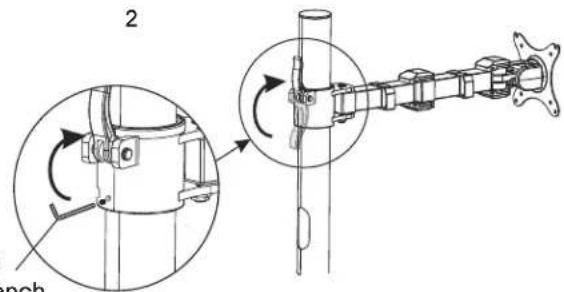
text_image
2 rench3
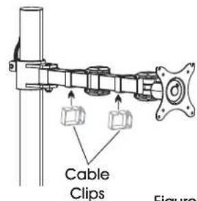
text_image
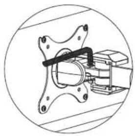
Cable Clips FigureFigure 4
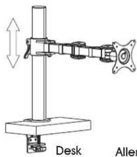
- Place monitor arm (3) over tube (4) and choose desired height of monitor. (See Figure 4)
- Flip lever on monitor arm to lock in place. Using a 3 x 3 Allen wrench, tighten the bolt directly underneath the lever to secure monitor arm.

CAUTION! Make sure lever is tightly locked before attaching monitor.
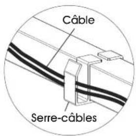
- Attach cable clips (2) to monitor arm.
ATTACHING MONITOR
1
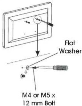
text_image
Flat Washer M4 or M5 x 12 mm Bolt2
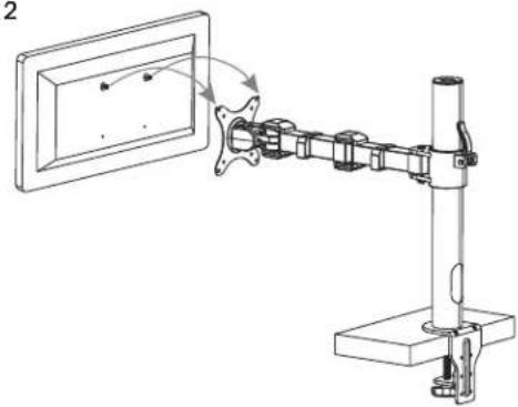
natural_image
Mechanical assembly diagram showing a mounted device with rotating arm and frame (no text or symbols)3
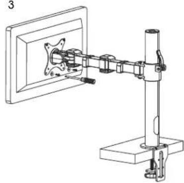
natural_image
Technical line drawing of a mechanical assembly mounted on a stand, showing components like brackets and mounting base (no text or symbols)Figure 5

NOTE: Two-person assembly is required for this step.

NOTE: Depending on size of holes, use either M4 x 12 mm bolts (A) or M5 x 12 mm bolts (B). If holes are not deep enough, add flat washers (E) to bolts to ensure a tight fit. (See Figure 5)
- One person should hold the monitor and align the bolt holes on the back of the monitor with the mounting plate. The second person should insert bolts into the top two holes in the mounting plate and monitor. Loosely tighten both bolts.

NOTE: For 100 x 100 mm VESA hole pattern, bolts can be inserted into the top holes in back of monitor and lowered into mounting plate for easier attachment.
- While one person continues to hold the monitor, the second person should insert bolts into the bottom two holes in the mounting plate and monitor. Then, fully tighten all four bolts.
ASSEMBLY CONTINUED
ADJUSTING MONITOR AND CABLE MANAGEMENT
1
natural_image
Technical line drawing of a mechanical assembly with flanged components and a central shaft (no text or symbols)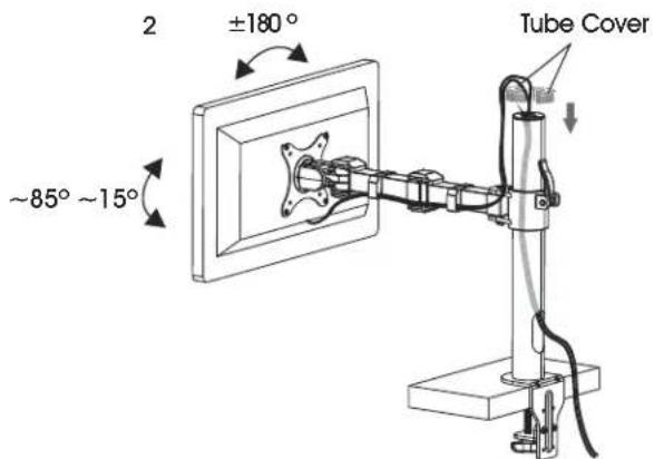
text_image
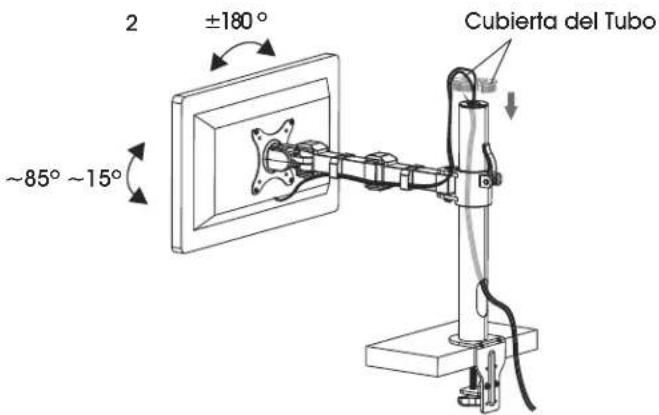
2 ±180° ~85° ~15° Tube Cover
text_image
Cable Cable ClipFigure 6
-
If the monitor is difficult to adjust, use a 5 x 5 mm Allen wrench (G) to loosen bolts at hinges of monitor arm and mounting plate as needed. (See Figure 6)
-
Cables can be managed by running them through cable clips on monitor arm and through the openings in tube.
ULINE H-7618
SOPORTE INDIVIDUAL PARA MONITOR – ESTÁNDAR
800-295-5510
uline.mx
natural_image
Technical line drawing of a mechanical assembly with no visible text or symbolsPARTES
text_image
Exploded view diagram of a mechanical assembly with numbered parts for identificationnatural_image
Technical line drawing of a mechanical assembly or mounting bracket with no visible text or symbolsAjuste
Diagrama 3

text_image
Technical diagram showing mechanical assembly with labeled components and directional arrows indicating motion or assembly.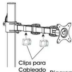
natural_image
Diagram of a mechanical arm assembly with rotating components and a wall-mounted frame (no text or symbols)
natural_image
Technical line drawing of a mechanical assembly mounted on a stand, showing components and mounting bracket (no text or symbols)Diagrama 5

natural_image
Technical line drawing of a mechanical assembly with no visible text or symbolsDiagrama 6
text_image
2 ±180° ~85° ~15° Cubierta del Tubo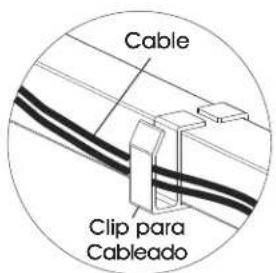
natural_image
Technical line drawing of a mechanical assembly with no visible text or symbolsPIÈCES

text_image
Exploded view diagram of a mechanical assembly with numbered parts for identificationFIXATION AVEC PASSE-FILS
natural_image
Mechanical assembly diagram showing a shaft and housing with rotating components (no text or labels)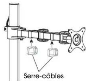
text_image
Serre-câblesFigure 4
natural_image
Mechanical assembly diagram showing a mounted device with rotating arm and mounting base (no text or symbols)
natural_image
Technical line drawing of a mechanical assembly mounted on a stand, showing components like a bracket and mounting base (no text or symbols)Figure 5

natural_image
Mechanical assembly diagram showing a valve mechanism inside a circular frame (no text or labels)
text_image
2 ±180° -85° ~ 15° Couvercle de tube