H-7620 - Flat screen mount Uline - Free user manual and instructions
Find the device manual for free H-7620 Uline in PDF.

User questions about H-7620 Uline
0 question about this device. Answer the ones you know or ask your own.
Ask a new question about this device
Download the instructions for your Flat screen mount in PDF format for free! Find your manual H-7620 - Uline and take your electronic device back in hand. On this page are published all the documents necessary for the use of your device. H-7620 by Uline.
USER MANUAL H-7620 Uline
TOOLS NEEDED
Phillips Screwdriver
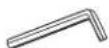
4 x 4 Allen Wrench (F)
5 x 5 Allen Wrench (G) (included)

Two Person Assembly
Required
natural_image
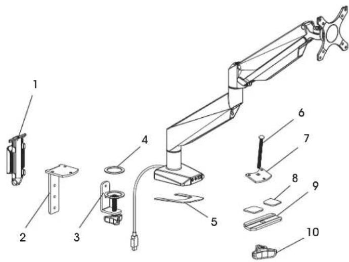
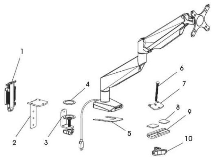
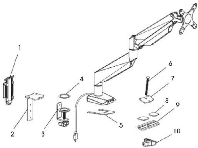
Technical line drawing of a mechanical arm with articulated joints and a cable (no text or symbols)PARTS
text_image
Technical diagram of a mechanical arm assembly with numbered parts for identification| # | DESCRIPTION QTY. | |
| 1 | Cable Clip 1 | |
| 2 | Clamp Mounting Bracket 1 | |
| 3 | Clamp 1 | |
| 4 | Anti-Slip Foam for Clamp 1 | |
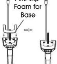
| 5 | Anti-Slip Foam for Base 1 | |
| 6 | Grommet Bolt | 1 |
| 7 | Grommet Mounting Plate 1 | |
| 8 | Anti-Slip Foam for Bottom Support | 2 |
| 9 | Bottom Support | 1 |
| 10 | Knob | 1 |
| A | M4 x 12 mm Bolt (Not Shown) | 4 |
| B | M5 x 12 mm Bolt (Not Shown) | 4 |
| C | M6 x 12 mm Bolt (Not Shown) | 3 |
| D | M6 x 10 mm Bolt (Not Shown) | 2 |
| E | Flat Washer (Not Shown) | 8 |
SETUP

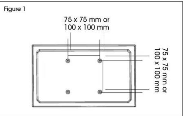
NOTE: Make sure the monitor has a VESA hole pattern of 75 x 75 mm or 100 x 100 mm. (See Figure 1)

NOTE: If the monitor is attached to a fixed base, remove monitor from base.

CAUTION! Be careful not to scratch the monitor screen during installation.
text_image
Figure 1 75 x 75 mm or 100 x 100 mm 75 x 75 mm or 100 x 100 mmASSEMBLY
CLAMP MOUNTING
text_image
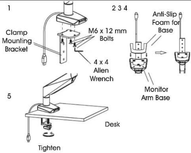
1 Clamp Mounting Bracket 2 3 4 M6 x 12 mm Bolts 4 x 4 Allen Wrench Anti-Slip Foam for Base Monitor Arm Base 5 Desk Tighten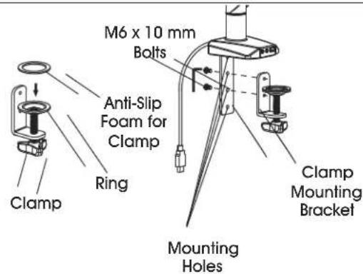
text_image
M6 x 10 mm Bolts Anti-Slip Foam for Clamp Ring Clamp Mounting Holes Clamp Mounting BracketFigure 2

NOTE: Clamp mount is compatible with desk thickness of 3/4 - 4^3/_4 .
- Attach clamp mounting bracket (2) to bottom of monitor arm base using M6 x 12 mm bolts (C) and 4 x 4 Allen wrench (F). (See Figure 2)
- Apply anti-slip foam for base (5) to bottom of monitor arm base.
-
Apply anti-slip foam for clamp (4) over ring on clamp (3).
-
Attach clamp (3) to the clamp mounting bracket (2) using M6 x 10 mm bolts (D) and 4 x 4 Allen wrench (F).

NOTE: Select the appropriate mounting holes based on the thickness of the desk.
- Place clamp mounting bracket and clamp over desk and fully tighten knob.
GROMMET MOUNTING
12345
text_image
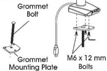
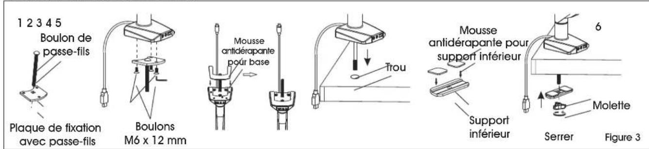
Grommet Bolt Grommet Mounting Plate M6 x 12 mm BoltsAnti-Slip
text_image
Foam for Base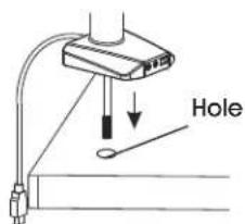
text_image
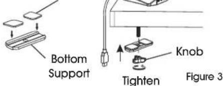
HoleAnti-Slip Foam for Bottom Support
text_image
Bottom Support Tighten Knob Figure 3
NOTE: For grommet mounting, hole in desk must be 3/8 - 2^3/4 .

NOTE: Grommet mount is compatible with desk thickness of 1 - 378 ".
- Insert grommet bolt (6) through center of grommet mounting plate (7); counterbore side down. (See Figure 3)
-
Attach grommet mounting plate (7) to bottom of monitor arm base using M6 x 12 mm bolts (C) and 4 x 4 Allen wrench (F).
-
Apply anti-slip foam for base (5) to bottom of monitor arm base.
- Insert grommet bolt (6) into hole of desk.
- Apply anti-slip foam for bottom supports (8) to bottom support (9).
- Thread grommet bolt (6) through bottom support (9) and attach knob (10) to end of bolt. Fully tighten knob.
ASSEMBLY CONTINUED
ATTACHING MONITOR
1
text_image
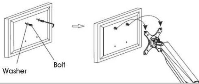
Washer Bolt2

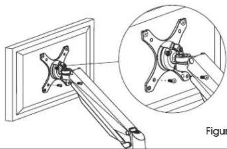
natural_image
Technical line drawing of a mechanical assembly with an inset close-up showing a bracket and pin (no text or symbols)Figure 4

NOTE: Two-person assembly is required for this step.

NOTE: Depending on size of holes, use either M4 x 12 mm bolts (A) or M5 x 12 mm bolts (B). If holes are not deep enough, add flat washers (E) to bolts to ensure a tight fit.
- One person should hold the monitor and align the bolt holes on the back of the monitor with the mounting plate. The second person should insert bolts into the top two holes in the mounting plate and monitor. Loosely tighten both bolts. (See Figure 4)

NOTE: For 100 x 100 mm VESA hole pattern, bolts can be inserted into the top holes in back of monitor and lowered into mounting plate for easier attachment.
- While one person continues to hold the monitor, the second person should insert bolts into the bottom two holes in the mounting plate and monitor. Then, fully tighten all four bolts.
ADJUSTING MONITOR

NOTE: Easy-adjust monitor includes a built-in counterweight system for free range of motion. Arm or mount may need to be adjusted to allow monitor to stop at desired position.
- To adjust the counterweight, use 5 x 5 Allen wrench (G) on bolt above middle joint. Turn towards "-" if monitor raises when released. Turn towards "+" if the monitor lowers when released. Adjust until mount can be stopped at desired position. (See Figure 5)
- To adjust the tilt function, use 5 x 5 Allen wrench (G) and 4 x 4 Allen wrench (F) on bolts near mounting plate. (See Figure 5)
Figure 5
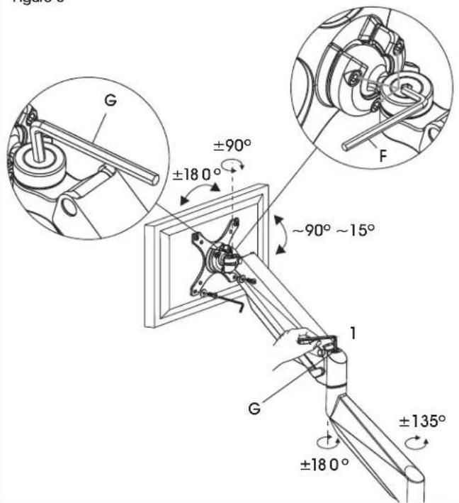
text_image
G ±90° ±18 0° F ~90° ~15° 1 G ±135° ±18 0°ASSEMBLY CONTINUED
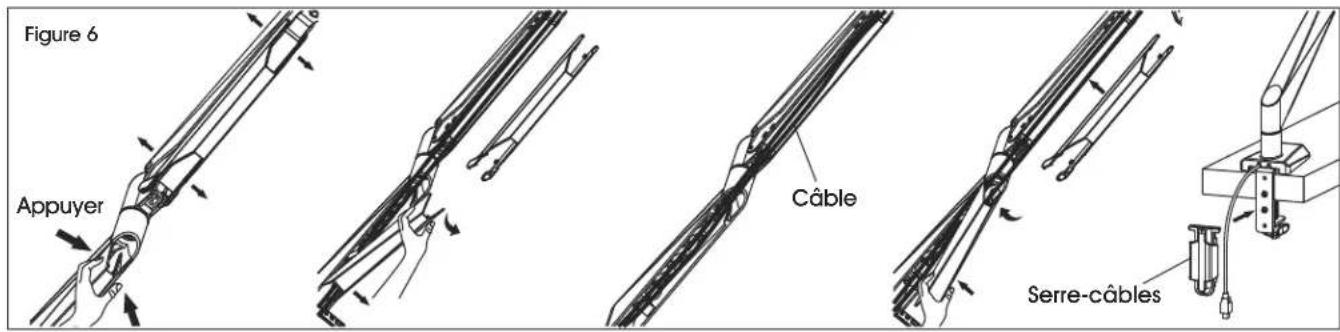
CABLE MANAGEMENT
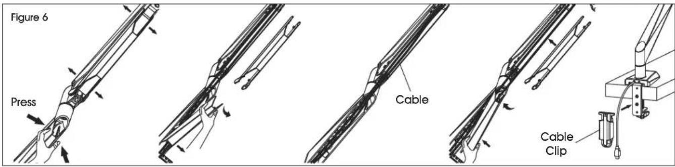
text_image
Figure 6 Press Cable Cable Clip- Press both sides of cable cover and pull off to remove. (See Figure 6)
-
Run cables along monitor arm and reattach cable cover over cables.
-
Attach cable clip (1) to back of clamp mounting bracket (2). Run cables through cable clip for a clean appearance.
ULINE H-7620
SOPORTE INDIVIDUAL PARA MONITORES – FÁCIL DE AJUSTAR
800-295-5510
uline.mx
natural_image
Technical line drawing of a mechanical arm with attached clamping device (no text or symbols)PARTES
text_image
Exploded view diagram of a mechanical arm assembly with numbered parts for identificationnatural_image
Technical line drawing of a mechanical assembly with an inset close-up showing a bracket and shaft (no text or symbols)Diagrama 4

text_image
G ±90° ±180° F ~90° ~15° 1 G ±135° ±180°natural_image
Line drawing of a mechanical arm with attached cable and connector (no text or symbols)PIÈCES
text_image
Exploded view diagram of a mechanical arm assembly with numbered parts for identificationFIXATION AVEC PASSE-FILS
natural_image
Technical line drawing of a mechanical assembly with an inset close-up showing a bracket and mounting detail (no text or symbols)Figure 4

text_image
Figure 6 G ±90° ±180° -90° ~15° F 1 G ±135° ±180°MONTAGE SUITE
GESTION DES CÂBLES