
H-1075 - Vacuum packaging machines Uline - Free user manual and instructions
Find the device manual for free H-1075 Uline in PDF.

User questions about H-1075 Uline
0 question about this device. Answer the ones you know or ask your own.
Ask a new question about this device
Download the instructions for your Vacuum packaging machines in PDF format for free! Find your manual H-1075 - Uline and take your electronic device back in hand. On this page are published all the documents necessary for the use of your device. H-1075 by Uline.
USER MANUAL H-1075 Uline
TOOLS NEEDED
Phillips
Screwdriver
Flat Head
Screwdriver
Adjustable Wrench
Shears or Scissors
natural_image
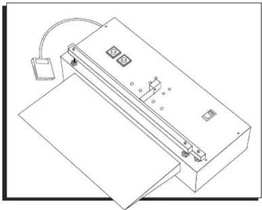
Technical line drawing of a mechanical device with mounting base and control panel (no text or symbols)PARTS
text_image
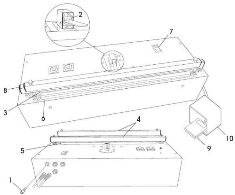
Technical diagram of a device with numbered components and an inset view of a mechanical assembly| # | DESCRIPTION QTY | |
| 1 | Fuse/10 Amp 1 | |
| 2 | Nozzle Assembly 1 | |
| 3 | Teflon Cover Set 20" 1 | |
| 4 | 20" Pressure Bar Cover Set | 1 |
| 5 | Heating Element 20 x 1/4" | 1 |
| 6 | Pad Assembly | 1 |
| 7 | On/Off Switch | 1 |
| 8 | Silicon Rubber Pressure Bar Cap | 4 |
| 9 | Foot Pedal Assembly with Switch | 1 |
| 10 | Orange Foot Guard | 1 |
| 96" 1/4 Blue Tubing (Not Shown) | 1 |
SAFETY
- To ensure safe operation, the operator should be familiar with the pinch points and a possible burn hazard near the seal jaw area. Warning stickers mark the location of these hazards.
- Do not wear neckties, jewelry or loose clothing when operating the sealer.
- Do not operate, troubleshoot or maintain the sealer under the influence of any drug or alcohol.
• Always observe all safety warnings and notices on the machine and in this manual.
- DO NOT use flammable or toxic cleaning fluids such as gasoline, benzene or ether.

CAUTION! Keep hands, fingers and flammable objects out of the seal jaw area. If a foreign object is caught between the jaws, turn main power switch to OFF immediately to prevent possible burns.
CONTROLS

NOTE: See references on page 3.
MAIN POWER SWITCH – Turns power off and on.
FOOT SWITCH – Controls vacuum cycle and initiates seal cycle.
HEAT TIMER – Controls heating time. To increase heat, turn heat timer knob clockwise. To decrease, turn knob counterclockwise. Timer is set in seconds – 10 seconds maximum.
COOL TIMER – Controls amount of time that pressure bar remains closed for cooling. To increase cool time, turn cool timer knob clockwise. To decrease, turn knob counterclockwise. Timer is calibrated in increments of 1/10 minute.
LED INDICATORS ON HEAT/COOL TIMERS:
- UNLIT: Timer is not active.
• SOLID COLOR: Timer is active. - FLASHING: Timer has timed-out.
OPERATION
SETUP
- Place the sealer on a flat working surface.
- Locate the "Air In" port on rear.
- Attach clean, dry air supply using 1/4" OD plastic tubing (supplied with sealer).
- Verify air pressure.

CAUTION! Do not exceed 85 psi.
START-UP

WARNING! Keep fingers away from seal jaw.
- Insert plug into 120VAC, 60Hz outlet.
- Turn sealer ON by pressing main power switch.
- Set heat timer at #2 position (2 seconds) and cool timer at #1 (6 seconds).
OPERATION

IMPORTANT! If you are vacuuming a granular or fine substance, the machine will need a filter. Failure to use a filter will clog the ejector and the machine will not be able to vacuum.
-
Load the product into the bag and place the bag opening over the nozzle (between the sealing jaws). Pull the bag so its seal area is straight and crease-free.
-
Press foot switch. Jaws will close and heat timer LED will illuminate.
- Remove bag and inspect seal. If the seal is weak, increase heat timer slightly. Adjust cool timer to allow plastic to cool before pressure bar reopens.
- Hold foot switch until desired vacuum level is achieved. Sealing cycle will initiate when Foot Switch is released.
- The sealing jaws will automatically release when heating and cooling cycles are completed. The machine will then return to its pre-set heating and cooling cycles.
- Continuously monitor seal area. If the area overheats, lower heating time and increase cooling time.
- At the end of each shift or production run, turn sealer OFF by pressing the main power switch.

NOTE: Sealing cycle may be aborted at any time by turning main power switch to "OFF."
HEATING TIPS
- Uline recommends cooling time should be double the heating time.
- To extend element life and avoid overheating, set heat timer at the lowest number for the required seal. Slight adjustments can significantly change results.
OPERATION CONTINUED
VACUUM TIPS
- For sealing heavy bags, heat time may need to be increased slightly.
- Practice the above process by setting the Heat Timer at zero and operating the machine in the vacuum mode only. This allows the operator to become familiar with the vacuum process without wasting bags.
- If available, attach the optional support tray. The tray aligns the product with the nozzle, leaving the operator's hands free to work with the bag.
-
The most desirable operator position is normally at waist level. Otherwise, bag may be misaligned with nozzle, affecting the evacuation flow.
-
Move product as close to the nozzle as possible without interfering with front vacuum bar. The product's thickness will prevent the bag from collapsing in front of the nozzle.
- If the product is thick or bulky, reposition slightly further from the vacuum jaw to prevent creases in the seal area.
- As the vacuum jaw closes, gently pull the bag back and up, away from the nozzle. Otherwise, the bag may collapse in front of the nozzle.
MAINTENANCE

IMPORTANT! At the start of each shift or production run, inspect the seal jaw area.
- Check the Teflon ^® tape covering the heating element for wrinkles, bumps or burn marks. If present, remove and reapply covering to smooth them out. For burn marks, replace with new Teflon ^® covers.
- Inspect the element for kinks or signs of overheating. If present, replace with element of same length and width.
- When replacing an element, also check Teflon ^96 cover and EPA's insulated backing under the element. Replacement is necessary if burns, bubbles or other surface defects are present.
- Also check the pressure bar for burns and replace if necessary.
CLEANING

CAUTION! Prior to cleaning, always unplug the machine. Never immerse or spray the sealer with a hose. Failure to follow these instructions can lead to fire, electrical shock or premature machine failure.

IMPORTANT! Use only denatured alcohol or soap and water to wipe down your sealer.
FILTER KIT INSTALLATION
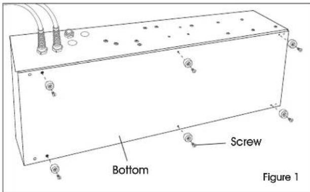
- Remove six screws inside rubber feet on bottom of machine. (See Figure 1)
text_image
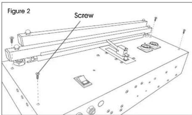
Bottom Screw Figure 1- Remove four screws on short ends on top of machine (two on each side). (See Figure 2)
text_image
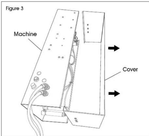
Figure 2 Screw- Remove cover from bottom of machine. (See Figure 3)
text_image
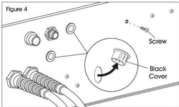
Figure 3 Machine Cover- Pry out two black covers on back wall of machine. Unscrew leftmost screw on back wall of machine. (See Figure 4)
text_image
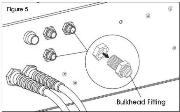
Figure 4 Screw Black Cover- Install the two bulkhead fittings through the holes and secure them tightly. (See Figure 5)
text_image
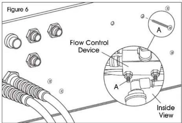
Figure 5 Bulkhead Fitting- Remove one of the bolts (A) holding the two flow control devices attached to the inside back wall of the machine. (See Figure 6)
text_image
Figure 6 Flow Control Device Inside ViewFILTER KIT INSTALLATION CONTINUED
- Attach the vacuum filter to the outside of the machine using this hole and the hole where the screw was removed in step 4. (See Figure 6)
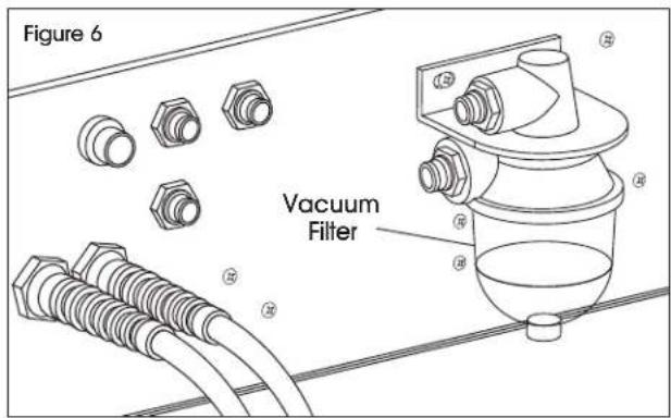
text_image
Figure 6 Vacuum Filter- Remove vacuum hose from vacuum ejector (B) and the back of vacuum nozzle (C). (See Figure 7)
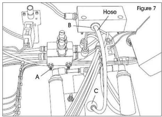
text_image
Figure 7 Hose B A C- Cut a piece of hose, provided with the vacuum filter kit, and attach it to the bulkhead fitting marked "To Vac Nozzle" from the inside of the machine and the back of the vacuum nozzle (C). (See Figure 8)

text_image
Figure 9 To Vac Nozzle C- Cut a piece of hose, provided with the vacuum filter kit, and attach it to the vacuum ejector (B) and the bulkhead fitting marked "From Ejector" from the inside of the machine. (See Figure 9)
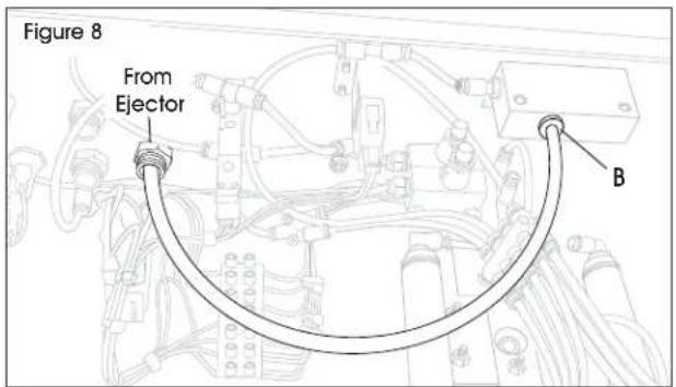
text_image
Figure 8 From Ejector B- Cut a piece of hose, provided with the vacuum filter kit, and attach it to the bulkhead fitting marked "From Ejector" on the outside of the machine and the upper fitting of the vacuum filter. (See Figure 10)
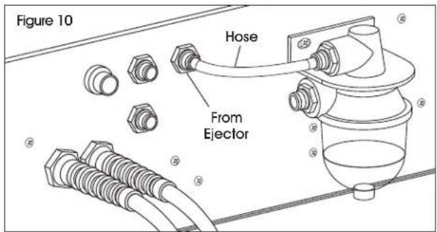
text_image
Figure 10 Hose From Ejector- Cut a piece of hose, provided with the vacuum filter kit, and attach it to the bulkhead fitting marked "To Vac Nozzle" on the outside of the machine and the bottom fitting of the vacuum filter. (See Figure 11)
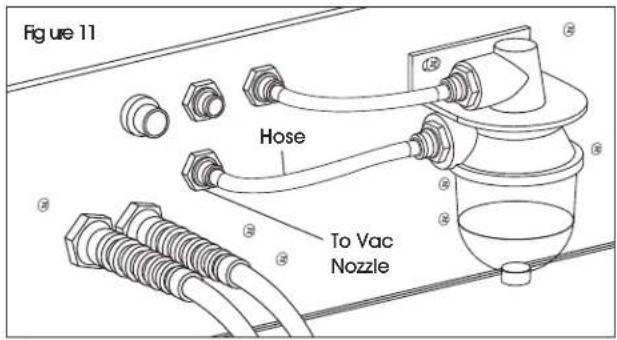
text_image
Figure 11 Hose To Vac NozzleREFERENCE
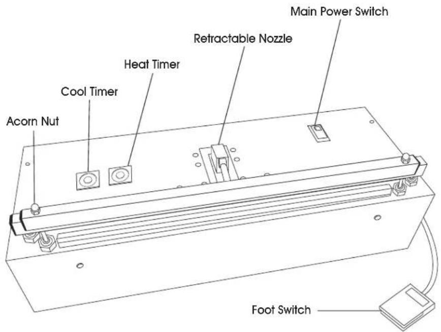
text_image
Main Power Switch Retractable Nozzle Heat Timer Cool Timer Acorn Nut Foot Switch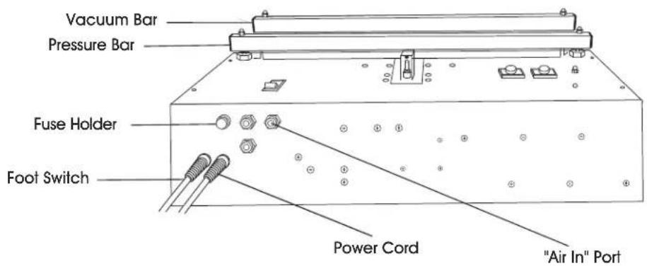
text_image
Vacuum Bar Pressure Bar Fuse Holder Foot Switch Power Cord "Air In" PortTROUBLESHOOTING
| OPERATING ISSUE ACTIONS RECOMMENDATIONS | ||
| No green power light. | Check main power switch. | Is power switch in the ON position? |
| Check fuse. | Replace fuse if necessary. | |
| Is the machine operating? | If yes, green lamp is out on the main power switch. Replace power switch. | |
| Has the machine's duty cycle increased? | Machine has automatically shut down to prevent overheating. Turn off power and allow machine to cool for 1/2 hour. Turn on main power. Call Uline Customer Service at 1-800-295-5510 if problem persists. | |
TROUBLESHOOTING CONTINUED
| OPERATING ISSUE ACTIONS RECOMMENDATIONS | ||
| No/poor vacuum. Check incoming air pressure. Check bag. | Air pressure should be set to 75-85 psi.Ensure bag is flat and crease-free between vac seal jaws. Use both hands to support bag.NOTE: Optional support tray may help when vacuuming larger/bulkier packages. | |
| No heat/poor or weak seal. | Increase heat time settings.Check element for hot spots or burn through. Element should be extended all the way to the right. | Replace element. Turn the sealer on again. |
| No heat. Check element finger nuts. Check contact surfaces. Check fuse. | Ensure they are tight with no gaps.Ensure all contact surfaces are clean.If burnt out, replace fuse. | |
| No cool. Check bag. Increase cool time. | ||
| Bag sticks to seal jaw. Check the pressure bar. Replace if necessary. | ||
| Gaps/creases in seal. Check bag. Check element and Teflon® for bumps, hot spots, burns or creases. | Ensure bag is flat when vac jaw closes.Increase heat and cool times. Replace element and Teflon® as necessary. | |
| Nozzle does not retract or extends too slow/fast. | Check incoming air pressure.Adjust nozzle extend flow control. | Air pressure should be set at 75-85 psi.Reduce/increase opening in nozzle extend flow control to slow down/speed up nozzle extend. |
| The pressure bar does not close. One side sticks open. | Realign pressure bar pistons. To realign, disconnect air pressure, close jaw by hand, loosen and retighten pressure bar piston nuts. | |
| Premature element burn out. Element is sparking. | Check procedure for proper element replacement. | Confirm flaps are facing up. Ensure nuts are tight and there are no gaps. |
| Jaws do not close. | Check incoming air pressure. | Air pressure should be set to 75-85 psi. |
natural_image
Technical line drawing of a mechanical device with mounting base and control panel (no text or symbols)PARTES

text_image
Technical diagram of a device with numbered components and an inset view of a mechanical assemblynatural_image
Technical line drawing of a mechanical device with mounting bracket and control panel (no text or symbols)PIÈCES


