
STEAM 35000 INV - Heat pump T.I.P. - Free user manual and instructions
Find the device manual for free STEAM 35000 INV T.I.P. in PDF.

| Product type | Inverter pool heat pump |
| Brand | T.I.P. |
| Model | STEAM 35000 INV |
| Dimensions (L x W x H) | 88 x 32 x 60.5 cm |
| Net weight | 34 kg |
| Power supply | 220-240 V~ / 50 Hz |
| Max. input power | 2.2 kW |
| Heating capacity (at 26°C ambient, 26/28°C water) | 7.5 - 2.2 kW |
| COP (coefficient of performance) | 13.3 - 6.7 |
| Min./max. water flow | 2.5 / 3.8 m³/h |
| Max. pool size | 35 m³ |
| Ambient temperature range | -10 to 43 °C |
| Heating temperature range | 15 - 40 °C |
| Cooling temperature range | 8 - 28 °C |
| Refrigerant | R32 (Difluoromethane), 0.31 kg |
| Evaporator type | Copper fins |
| Heat exchanger | Titanium |
| Protection rating / Class | IPX4 / I |
| Noise level (at 10 m) | 19 - 27 dB |
| Hydraulic connection | 1 1/2" internal thread |
| Power cable length | 2.8 m |
| Main functions | Inverter heating, cooling, fixed mode, ECO mode, programmable timer, frost protection |
| Maintenance | Clean the evaporator with a soft brush, drain before winter, annual checks |
| Safety | PRCD switch (30 mA), R32 refrigerant leak protection, automatic shutdown in case of fault |
| Spare parts and repairability | Parts available at www.tip-pumpen.de; repair by qualified personnel only |
| General information | Domestic use for private pool, installation with bypass, compatible with salt water up to 10% |
Frequently Asked Questions - STEAM 35000 INV T.I.P.
User questions about STEAM 35000 INV T.I.P.
0 question about this device. Answer the ones you know or ask your own.
Ask a new question about this device
Download the instructions for your Heat pump in PDF format for free! Find your manual STEAM 35000 INV - T.I.P. and take your electronic device back in hand. On this page are published all the documents necessary for the use of your device. STEAM 35000 INV by T.I.P..
USER MANUAL STEAM 35000 INV T.I.P.
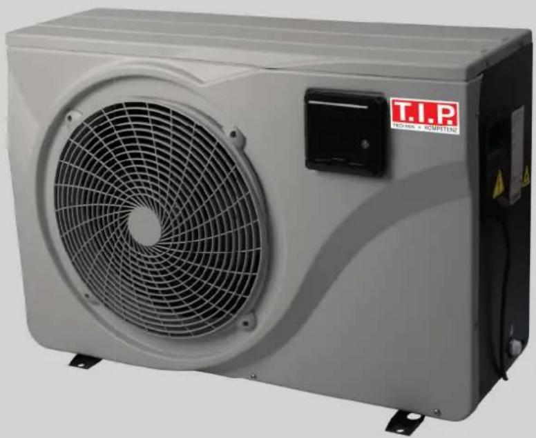
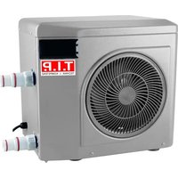
natural_image
Exterior view of a white industrial air conditioning unit with a circular fan and control panel (no visible text or symbols on the device itself)STEAM 35000 INV
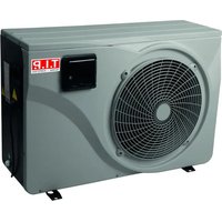
natural_image
Exterior view of a white industrial air conditioning unit with a circular fan and control panel (no visible text or symbols on the device itself)STEAM 45000 INV

Translation of original operating instructions
Inverter pool heat pump

GB EC declaration of conformity
We, T.I.P. Technische Industrie Produkte GmbH, Siemensstr. 17, D-74915 Waibstadt, declare in our sole responsibility that the products identified below comply with the basic requirements imposed by the EU directives specified below including all subsequent amendments: 2014/35/EU, 2014/30/EU, 2011/65/EU.
natural_image
Technical line drawing of two air conditioning units with fan blades and ventilation system (no text or symbols)Abb. 1
Congratulations for buying your new device from T.I.P.!
Please read through these operating instructions carefully to make sure that you can fully benefit from all features.
We hope you will enjoy your new device!
Table of contents
- General safety information.... 1
- Intended use 3
- Technical data.... 3
- Scope of delivery 3
- Commissioning 4
- Maintenance 10
- Warranty 12
- How to order spare parts.... 13
- Service 13
1. General safety information
Please read through these operating instructions carefully and make yourself conversant with the control elements and the proper use of this product. We shall not be liable in the case of damage caused as a result of the non-observance of instructions and provisions of the present operating instructions. Any damage caused as a result of the non-observance of the instructions and regulations contained in the present operating instructions shall not be covered by the warranty terms. Please keep these operating instructions in a safe place and hand them on together with the device should you ever dispose of it.
Persons not familiar with the contents of these manual may not use this device.
The device must not be used by children.
The device may be used by persons with reduced physical, sensory or mental capabilities or lack of experience and / or knowledge if they have been supervised or instructed in the safe use of the equipment and have understood the resulting hazards. Children are not allowed to play with the device. Keep the appliance and its cord out of reach of children.
The device must not be used when people or animals are in the water.
The device must be supplied through a residual current device (RCD) having a rated residual operating current not exceeding 30mA.
The mains power connection of this device cannot be replaced. In case the line is damaged, the device must be scrapped.
Notes and instructions with the following symbols require particular attention:

Any non-observance of these instructions involves the danger of bodily harm to people and/or damage to property.
Any non-observance of this instruction bears the risk of an electrical shock which may cause damage to persons or property.
Please inspect the device for damage occurred during transportation. In case of damage, the retailer has to be informed immediately, at the latest within 8 days after the date of purchase.
In addition to the basic safety precautions for avoiding accidents, please note the following:
- ATTENTION: Before performing any installation or maintenance tasks, disconnect the electrical device from the power source by pulling the plug out of the socket outlet. Switch off the main fuse of the main domestic power supply before unplugging the mains cable, if the connection plug or the main power outlet are wet. Never transport or suspend the device by the mains cable.
- Ensure that the voltage specified on the type plate of the device agrees with the mains voltage.
-
Prior to connecting the device to the mains supply, ensure that the mains cable and the device are not damaged in any way.
-
Parts of the packaging can be dangerous (e.g. the plastic bags) - therefore keep these out of reach of children, people who not responsible for their actions and animals.
- Only use accessories that are included in the scope of delivery, or only those that are specified in the operating manual. The use of accessories that have not been approved may impair safety.
- Any use of the device that is not described in this manual may be dangerous and must therefore be avoided.
- The device must be correctly assembled with all parts before use. Check that the socket and plug match.
- Never touch the mains plug with wet hands.
- Switch off the device before maintenance, cleaning and after use, and unplug from the mains.
- Do not leave the device within the reach of children or people who are not responsible for their actions.
- Children should be supervised so that they do not play with electrical devices.
- In case of incidents (e.g. contact with cleaning agents or chemicals) clean the machine with plenty of clean water.
- In the event of a malfunction, always pull out the mains plug to avoid any danger.
- Carefully check whether the mains connection cable, housing or other parts of the device are damaged; if so, do not use the device under any circumstances and contact the customer service department for repairs.
- If you are using extension cables, make sure that they are suitable for the application in question and that they are placed on a dry surface and protected against water spray.
- Service and repairs shall only be carried out by qualified personnel. Defective parts of the device shall only be replaced with original parts.
- The manufacturer is not responsible for any damage to persons or objects caused by improper use of the device, or by a failure to follow the instructions provided in this manual.
3.1. Special safety instructions - Heat pump
- Do not install near a heat source, combustible materials or building exhaust air.
- If the installation is not in a location with restricted access, a heat pump protection grille must be fitted.
- To avoid serious burns, do not touch the pipelines during installation or maintenance.
- To avoid serious burns, switch off the heat pump before carrying out any work on the refrigerant system and wait a few minutes before attaching temperature and pressure sensors.
- Have the refrigerant level checked when servicing the heat pump.
- Check that there are no traces of corrosion or oil stains around the refrigerant components.
- Have the installation, initial commissioning and maintenance of the heat pump carried out by authorised specialists only.
- Do not start work on the heat pump until all safety instructions have been checked.
- The device must be stable.
- The electrical installation must function properly.
- The hydraulic connections must be tight.
- All unnecessary tools and objects must be cleared from the area.
Danger to life due to unsuitable water temperature!
Staying in pools with water temperatures that are too high or too low for a long time can cause overheating (body temperature above 38^ C) or hypothermia (body temperature below 35^ C). This can lead to fatigue, dizziness, fainting or unconsciousness, resulting in death by drowning in the pool. Pregnant women run the risk of causing deformities or brain damage to their unborn child, especially in the first three months of pregnancy.
- Keep the water temperature in the range of 26-30°C during normal swimming operation.
- Do not allow children and pregnant women to enter the water at water temperatures above 38°C.
- Do not allow the water temperature to rise above 40^ .
- If in doubt, check the water temperature with a suitable precision thermometer before entering the water. (The temperature sensor of the heat pump guarantees an accuracy of approx. ± 3^ .)
Fire and explosion hazard due to leaking heat exchanger fins!
The refrigerant circuit of the finned heat exchanger contains easily combustible, odourless gas under high pressure. There is a risk of fire and explosion if refrigerant escapes in an uncontrolled manner.
- Keep heat sources and open fires away from the heat pump.
- Do not drill or burn the heat pump.
- Do not use any objects, except those permitted by the manufacturer, to accelerate the defrosting process.
- Shut down the heat pump immediately if you suspect refrigerant leakage.
- The refrigerant is odourless. Always keep ignition sources away from the installation site of the heat pump.
- Contact an authorised specialist as soon as you suspect refrigerant leakage.
Danger of injury when moving heavy devices!
The device is heavy! Incorrect lifting or uncontrolled tilting of the device may result in injury or damage to the device.
- Lift, carry or tilt the device at least in pairs, never alone.
- Ensure correct posture (straight back, safe stance, etc.).
- Use transport aids (e.g.: Pallet truck or dolly).
- Wear protective equipment such as safety shoes or gloves.
2. Intended use
This device is intended for private use at home and not for commercial or industrial purposes. Use the device only for heating and cooling pool equipment.
3. Technical data
| Model | STEAM 35000 INV | STEAM 45000 INV |
| Voltage / frequency | 220 - 240 V~ / 50 Hz | 220 - 240 V~ / 50 Hz |
| Max. input | 2.2 kW | 3.0 kW |
| Heating capacity * | 7.5 - 2.2 kW | 10.4 - 2.5 kW |
| Input | 1.1 - 0.2 kW | 1.5 - 0.2 kW |
| COP | 13.3 - 6.7 | 13.3 - 6.9 |
| EER (energy efficiency ratio) | 5,01 - 3,63 | 5,59 - 3,79 |
| Min. / max. flow rate | 2.5 m3/h / 3.8 m3/h | 3.3 m3/h / 5.0 m3/h |
| Max. pool size | 35 m3 | 45 m3 |
| Outdoor temperature | -10 - 43 °C | -10 - 43 °C |
| Heating temperature | 15 - 40 °C | 15 - 40 °C |
| Cooling temperature | 8 - 28 °C | 8 - 28 °C |
| Pool water PH value | 6.9 - 8.0 | 6.9 - 8.0 |
| Max. salinity | 10 % | 10 % |
| Mains cable | 2.8 m | 2.8 m |
| Refrigerant type / quantity | R32 (difluoromethane) / 0.31 kg | R32 (difluoromethane) / 0.42 kg |
| Global Warming Potential GWP / CO2 equivalent | 675 / 0.209 t | 675 / 0.284 t |
| Evaporator type | Copper fins | Copper fins |
| Compressor type | GMCC | GMCC |
| Number of compressors | Single rotating | Single rotating |
| Heat exchanger | Titan | Titan |
| Speed blower | 950 rpm | 950 rpm |
| Air flow rate | 2,100 m3/h | 2,100 m3/h |
| Min. pumping pressure | 0.23 MPa | 0.23 MPa |
| Max. pumping pressure | 1.18 MPa | 1.18 MPa |
| Degree of protection / protection class | IPX4 / I | IPX4 / I |
| Connection | 1 1/2" female | 1 1/2" female |
| Sound power level (10 m) | 19 - 27 dB | 20 - 28 dB |
| Dimensions | 88 x 32 x 60.5 cm | 88 x 32 x 60.5 cm |
| Net weight | 34 kg | 38 kg |
| Item no. | 30466 | 30467 |
*Values determined at: Outdoor temperature: 26 °C / Water temperature: 26/28 °C / Humidity: 80%.
4. Scope of delivery
Included in the product scope of supply are:
Pool heat pump with connection cable, connections, operating manual.
If possible, retain the packaging until your guarantee has expired. Dispose of packing materials in an environmentally friendly manner.
5. Commissioning

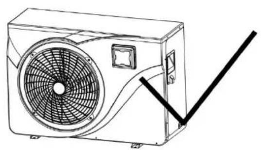
The device must be transported in an upright position. If it is stored or transported horizontally, it must stand upright for at least 24 hours before it can be switched on (Fig. 1).
natural_image
Line drawing of a wall-mounted air conditioner unit with fan and ventilation duct (no text or symbols)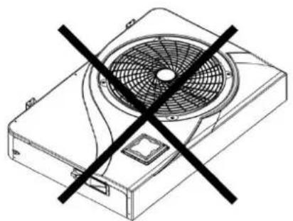
natural_image
Technical line drawing of a mechanical fan with a black X symbol indicating prohibition (no text or labels)Fig. 1
5.1 Placing of the heat pump
- The future location of the device should be easily accessible for convenient operation and maintenance.
- It must be placed on the ground, ideally on a level concrete floor. Ensure that the ground is sufficiently stable and can support the weight of the device.
- A water drainage device must be provided near the device to protect the installation area.
- If necessary, the device can be raised using suitable mounting pads designed for its weight.
- Ensure that the device is well ventilated, that the air outlet does not face the windows of neighbouring buildings and that the exhaust air cannot flow back.
- The device must not be installed when oil, flammable gases, corrosive products, sulphur-containing compounds or high-frequency devices are nearby.
- To avoid soiling, do not install the device near a road or path.
• To avoid annoying neighbours, ensure that the device is installed facing the least noise-sensitive area. -
Operate the device as far as possible out of the reach of children.
-
Leave a free space of 50~cm at the sides and rear of the heat pump (Fig. 2).
- Leave a free space of 2.5m at the front of the heat pump in relation to walls.
- Do not place any objects in front of or on the device. A minimum distance of 1 m from the front of the heat pump must be ensured.
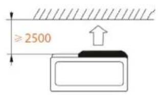
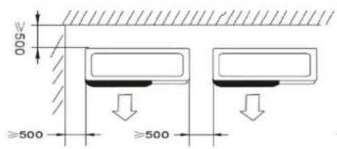
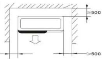
Fig. 2
Sound-absorbing underlays:
To minimise noise pollution caused by the vibrations of the heat pump, it can be placed on vibration-damping underlays.
All that is required is to position an underlay between the feet of the unit and the bracket and to secure the heat pump to the bracket with suitable screws.

flowchart
graph LR
    A["1"] --> B["2"]
    B --> C["3"]
    C --> D["4"]
    D --> E["5"]
    E --> F["6"]
    F --> G["7"]
    G --> H["8"]
    H --> I["9"]
    I --> J["10"]
    J --> K["11"]
    K --> L["12"]
    L --> M["13"]
    M --> N["14"]
    N --> O["15"]
    O --> P["FROM THE POOL"]
    P --> Q["TOWARDS THE POOL"]
    style A fill:#f9f,stroke:#333
    style B fill:#f9f,stroke:#333
    style C fill:#f9f,stroke:#333
    style D fill:#f9f,stroke:#333
    style E fill:#f9f,stroke:#333
    style F fill:#f9f,stroke:#333
    style G fill:#f9f,stroke:#333
    style H fill:#f9f,stroke:#333
    style I fill:#f9f,stroke:#333
    style J fill:#f9f,stroke:#333
    style K fill:#f9f,stroke:#333
    style L fill:#f9f,stroke:#333
    style M fill:#f9f,stroke:#333
    style N fill:#f9f,stroke:#333
    style O fill:#f9f,stroke:#333
    style P fill:#f9f,stroke:#333
    style Q fill:#f9f,stroke:#333
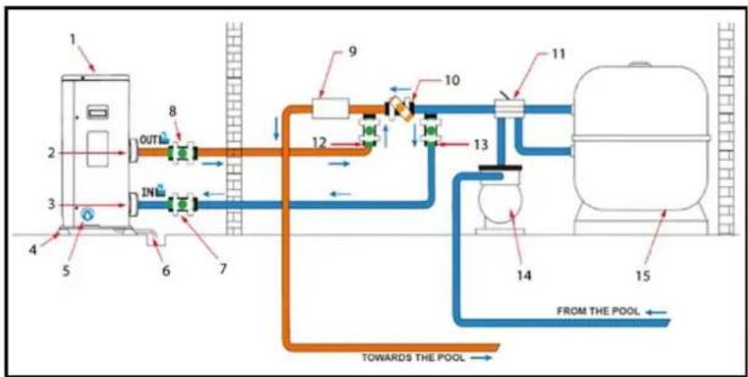
| Valve half open | |
| Valve open |
| 1. | Heat pump |
| 2. | Water outlet |
| 3. | Water inlet |
| 4. | Lifting bolt |
| 5. | Drain screw |
| 6. | Condensation drain |
| 7. | Regulating valve |
| 8. | Regulating valve |
| 9. | Processing system |
| 10. | Bypass |
| 11. | 4-way valve |
| 12. | Bypass |
| 13. | Bypass |
| 14. | Circulating pump |
| 15. | Filters |
5.2 Connecting the heat pump

Installation must be carried out by a qualified technician.
Condensation drain:
We recommend installing a condensation drain. To do this, raise the heat pump by at least 10 cm using suitable lifting bolts (waterproof) and connect the drain pipe to the opening in the bottom of the pump.
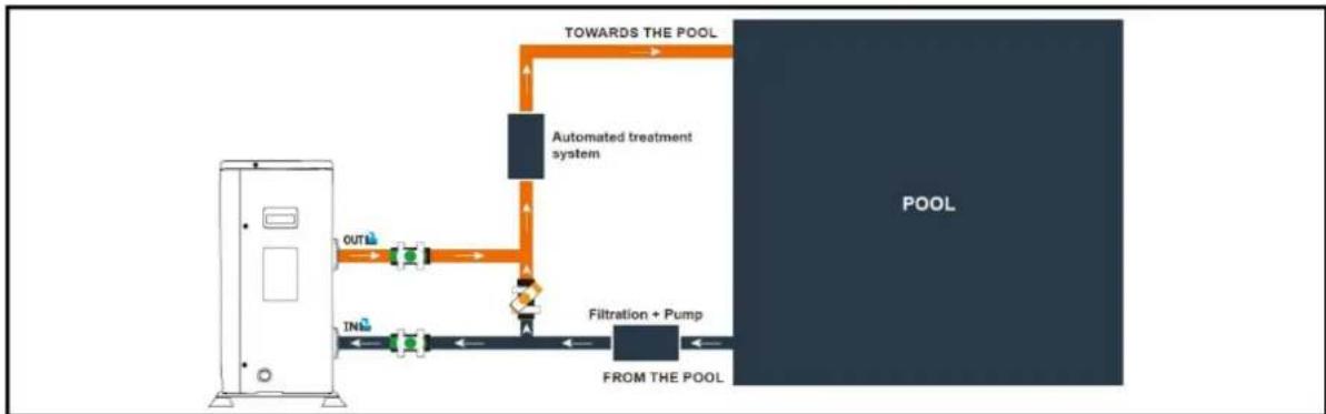
The heat pump must be connected to the pool via a bypass.
A bypass consists of 3 valves that regulate the flow circulating in the heat pump. For maintenance work, the bypass allows the heat pump to be disconnected from the system without interrupting its installation.
The filter located upstream of the heat pump must be cleaned regularly to ensure that the water in the system is clean, thus avoiding the operational problems associated with dirt or clogging of the filter. The water treatment system (chlorine or salt dosing system), on the other hand, must be installed after the heat pump (Fig. 4).
flowchart
graph LR
    A["Control Unit"] --> B["OUT"]
    B --> C["Flow Path with Inlet"]
    C --> D["Inlet"]
    D --> E["Filtration + Pump"]
    E --> F["From THE POOL"]
    F --> G["POOL"]
    G --> H["TOWARDS THE POOL"]
    H --> I["Automated treatment system"]
    I --> J["A"]
    J --> K["A"]
Fig. 4

The power supply to the heat pump must be disconnected before any intervention.

Servo control of a pump whose power exceeds 5A (1000W) requires the use of a relay.
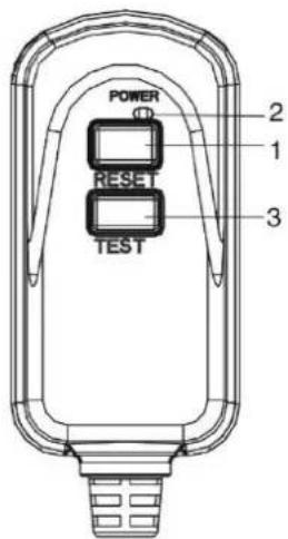
5.3 Connecting the personal protection switch (PRCD plug)
Switch explanation:
1.) RESET → Reset
- Activates the protection
2.) POWER → Red indicator
- Protection active
3.) TEST
- Activate the test function
Test the device before use:
- Insert the plug into the socket.
- Press the "RESET" button: The display must be "on".
- Press the "TEST" button: The display must be "off".
- Press the "RESET" button for use: The display must be "on".
- Caution: do not use if "TEST" fails.

This is not an overload protection, but a personal protection switch.
In the event of an electrical leak, the device automatically shuts off the power supply and prevents elect from entering the human body.
The device should be connected directly to a power outlet.
Power supply via an extension cable is not recommended.
Technical data PRCD plug
| Voltage / frequency | 220 - 250 V~ / 50 - 60 Hz |
| Rated current | 10 A / 16 A |
| Trip leakage current | 10 mA / 30 mA |
| Trip time | < 0,1 s |
| Degree of protection | IP54 |
5.4 Operation
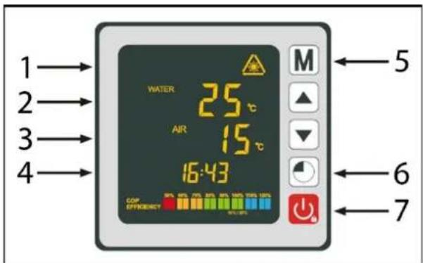
| 1. | Operating mode |
| 2. | Water temperature |
| 3. | Ambient temperature |
| 4. | Time |
| 5. | Button: Operating mode |
| 6. | Button: Time and timer |
| 7. | Button: ON/OFF |
Operating mode selection:

Before starting the heat pump, the filter pump must be checked for correct operation. The heat pump must never be operated without a pump.
- Press and hold for 3s to switch on your pump.
Before you set your desired temperature, you must first select an operating mode for your heat pump:
GB


Heating mode (inverter)
Select the heating mode for the heating pump to intelligently heat the water in your pool.
Fix mode (heating only)
Select the fix heating operating mode for the heat pump to heat the water in your pool with constant power.
ECO quiet mode
Select the silent heating operating mode so that the heat pump heats the water at reduced speed.
Cooling mode (inverter)
Select the cooling mode for the heat pump to intelligently cool the water in your pool.
Heating mode (inverter):
- Press and hold M for 3s to switch from one mode to the other until the heating mode is displayed.
- Use the and buttons to select the desired temperature (15-40°C).
Fix mode (heating only):
- Press and hold M for 3s to switch from one mode to the other until the FIX heating mode is displayed.
- Use the and buttons to select the desired temperature (15-40°C).
ECO quiet mode:
- Press and hold M for 3s to switch from one mode to the other until the ECO heating mode is displayed.
- Use the and buttons to select the desired temperature (15-40°C).
Cooling mode (inverter):
- Press and hold M for 3s to switch from one mode to the other until the cooling mode is displayed.
- Use the and buttons to select the desired temperature (8-28°C).
If cooling mode changes to heating mode or vice versa, the heat pump restarts after 10 minutes.
If the temperature of the incoming water is lower than the set temperature (-1 °C), the heat pump switches to heating mode. The compressor stops if the temperature of the incoming water is higher than the set temperature.

Under normal conditions, a suitable heat pump can warm the water in a swimming pool by 1^ C to 2^ C per day. It is therefore normal not to feel any temperature difference in the system when the heat pump is in operation.
A heated swimming pool should be covered to avoid any heat loss and thus be more efficient.
Setting the time on the device:
Set the system clock to the local time as follows:
- Press to set the time - the hours flash.
- Set the hours with the and buttons.
- Press to switch to the minutes.
- Set the minutes with the and buttons.
- Press to confirm the set time and return to the main screen.
Programming the timer:
This function allows you to programme the start/stop time. You can programme up to 3 different start/stop times. The setting is as follows:
- Press and hold for 3s to go to the timer function.
- Select the program to be configured with the and buttons.
- Press to programme the start time - ON lights up.
- Set the hours with the ▼ and buttons.
- Press to switch to the minutes.
- Set the minutes with the ▼ and ▲ buttons.
- Press to programme the stop time - OFF lights up.
- Set the hours with the ▼ and buttons.
- Press to switch to the minutes.
- Set the minutes with the ▼ and ▲ buttons.
- Press to return to the main screen.
Activating the timer:
After the program has been defined, it can be activated as follows:
- Press and hold for 3s to go to the timer function.
- Select the program to be activated with the ▼ and ▲ buttons.
- Press and hold the button until the ON/OFF indicators light up.
- Press to return to the main screen.
The pump switches itself off and starts and stops again at the set time.
The ON/OFF lights indicate an active program; the digit at the beginning of the line indicates the number of the active program.
Deactivating the timer:
After the program has been activated, it can be deactivated as follows:
- Press and hold for 3s to go to the timer function.
- Select the program to be deactivated with the ▼ and ▲ buttons.
- Press and hold the button until the ON/OFF indicator is no longer lit.
- Press to return to the main screen.
The ON/OFF lights indicate an active program; the digit at the beginning of the line indicates the number of the active program.
Status values:
The status values can be checked via the remote control by following the steps below:
- Press and hold the ▼ button until you enter the settings check mode.
- Press and to check the status values.
- Press to return to the main screen.
Table of status values:
| Code | Description |
| A01 | Water inlet temperature (-30~150°C) |
| A02 | Water outlet temperature (-30~150°C) |
| A03 | Ambient temperature (-30~150°C) |
| A04 | Outlet gas temperature (0~150°C) |
| A05 | Intake gas temperature (-30~150°C) |
| A06 | Coil outer temperature (-30~150°C) |
| A07 | Coil internal temperature (-30~150°C) |
| A08 | The openness of the expansion valve |
| A09 | Reserved |
| A10 | Compressor current (A) |
| A11 | PCB temperature (°C) |
| A12 | Fan motor current (A) |
| A13 | Real frequency of the compressor (Hz) |
| A14 | Motherboard current (A) |
| A15 | Fan motor speed (RPS) |
Querying of system parameters:

This procedure is to assist with maintenance and future repairs.
The default settings should only be changed by an experienced professional.

Any change to the reserved settings automatically voids the warranty.
Parameter table:
| Code | Description | Factory setting |
| P01 | Calibration of the temperature difference before restarting | 1 °C |
| P02 | Reserved | |
| P03 | Reserved | |
| P04 | Setting the cooling temperature | 27 °C |
| P05 | Setting the heating temperature | 27 °C |
| P06 | Protection against excessive discharge temperature | 120 °C |
| P07 | Discharge temperature too high reset temperature | 95 °C |
| P08 | Compressor current protection | Reserved |
| P09 | Setting the compensation coefficient of the temperature water inlet | 0 °C |
| P10 | Reserved | |
| P11 | Auto-activation time before de-icing starts | 45 min |
| P12 | De-icing activation temperature | -3 °C |
| P13 | Maximum de-icing time | 8 min |
| P14 | De-icing deactivation temperature | 20 °C |
| P15 | Temperature difference between ambient temperature and coil temperature during defrosting | 2 °C |
| P16 | Ambient temperature defrost | 17 °C |
| P17 | Extended valve action time | 45 s |
| P18 | Target superheat temperature during heating | 1 °C |
| P19 | Set the EXV discharge temperature | 95 °C |
| P20 | The openness of EXV | 300 |
| P21 | The mini opening for the electric expansion valve | 80 |
| P22 | EXV mode of operation | 1 = auto |
| P23 | EXV year level | 350 |
| P24 | Target superheat temperature during cooling | 3 °C |
| P25 | Water pump switch-off time after reaching the set temperature | 45 min |
| P26 | Operating time of the water pump after reaching the set temperature | 5 min |
| P27 | EXV mode of operation during cooling | 1 = superheat temp. |
| P28 | Filtration pump servo control mode | 1 = ON |
Note:
Parameter 01:
The heat pump is restarted after reaching the desired temperature (e.g. 27^ C) when the pool temperature drops to 26^ C (27 - 1).
Parameter 28:
Circulating pump control mode
When you switch on your heat pump, the circulating pump starts and 1 minute later the heat pump compressor is activated. When the heat pump stops running, its compressor and the fan switch off and after 30 seconds the circulating pump stops. During a defrost cycle, the circulating pump continues to operate regardless of the selected mode.
Frost protection / de-icing:
Note: For the frost protection system to work, the heat pump must be supplied with power and the circulating pump must be activated. If the circulating pump is servo-controlled by the heat pump, it is activated automatically.
When the heat pump is in standby mode, the system monitors the ambient temperature and the water temperature to activate the frost protection programme if necessary.
The frost protection programme is automatically activated when the ambient temperature or the water temperature is less than 2 °C and when the heat pump has been switched off for more than 120 minutes.
When the frost protection programme is running, the heat pump activates its compressor and the circulating pump to heat the water again until the water temperature exceeds 2 °C .
The heat pump automatically exits frost protection mode when the ambient temperature is greater than or equal to 2 °C or when the heat pump is activated by the user.
If you want to set de-icing outside the automatic frost protection programme:
- Press and hold and for 3s to initiate forced de-icing.
6. Maintenance
ATTENTION: Before performing any maintenance tasks, disconnect the electrical device from the power source by pulling the plug out of the socket outlet.

Do not use aggressive solvents or cleaning agents.

Do not dispose of pool water containing chemicals (e.g. chlorine) on lawns or plants.
The evaporator on the back of the heat pump must be cleaned carefully with a hoover and a soft brush attachment.
Note: All types of repairs must be carried out by qualified personnel.
Annual maintenance:
- Carry out security checks.
- Check the integrity of the electrical wiring.
- Check the earth connections.
Winter:
In the winter months, when the ambient temperature is lower than 3^ C, a decommissioned heat pump must be winterised to avoid frost damage.
- Disconnect the heat pump from the power supply.
- Open the bypass valve. Close the inlet and outlet valves.
- Unscrew the drain plug and the water pipes to drain the water from the heat pump.
- Screw back the drain plug and the pipes or plug them with rags to prevent foreign bodies from entering the circuit. Finally, protect the pump with its winter cover.
If a circulating pump is servo-controlled by the heat pump, drain it as well.
Help in case of faults:
| Code | Fault | Possible cause | Remedy |
| 03 | Flow sensor fault | Not enough water in the heat exchanger | Check the operation of the water circuit and the opening of the bypass valves |
| Sensor disconnected or defective | Reconnect or replace sensor | ||
| 04 | Freeze protection | Protection activated when the ambient temperature is too low and the device is in standby mode | No intervention is required |
| 05 | Protection against high pressure | Insufficient water flow | Check operation of water pump and bypass inlet/outlet valve openings |
| Excess refrigerant gas | Readjust refrigerant quantity | ||
| Defective 4-way valve | Replace the 4-way valve | ||
| High pressure switch disconnected or defective | Reconnect or replace high pressure switch | ||
| 06 | Low pressure protection | Insufficient refrigerant gas | Readjust refrigerant quantity |
| Defective 4-way valve | Replace valve | ||
| Low pressure switch disconnected or defective | Reconnect or replace low pressure switch | ||
| 09 | Connection problem between circuit board and wired controller | Poor connection | Check wiring connections between controller and PCB |
| Defective wired controller | Replace controller | ||
| Defective PCB | Replace PCB | ||
| 10 | Connection problem between PCB and inverter module | Poor connection | Check wiring connections between PCB and inverter module |
| Defective inverter module | Replace inverter module | ||
| Defective PCB | Replace PCB | ||
| 12 | Temperature of the ventilated air too high | Insufficient refrigerant gas | Readjust refrigerant quantity |
| 15 | Fault in the water inlet temperature sensor | Sensor disconnected or defective | Reconnect or replace sensor |
| 16 | Fault in the outdoor temperature of the coil | Sensor disconnected or defective | Reconnect or replace sensor |
| 18 | Venting temperature fault | Sensor disconnected or defective | Reconnect or replace sensor |
| 20 | Inverter module protection | See chapter Annexes | |
| 21 | Ambient temperature fault | Sensor disconnected or defective | Reconnect or replace sensor |
| 23 | Water temperature at outlet too low for cooling operation | Insufficient water flow | Check operation of water pump and bypass inlet/outlet valve openings |
| 27 | Water outlet fault | Sensor disconnected or defective | Reconnect or replace sensor |
| 29 | Stored temperature fault | Sensor disconnected or defective | Reconnect or replace sensor |
| 32 | Flow temperature too high for heating mode protection | Insufficient water flow | Check operation of water pump and bypass inlet/outlet valve openings |
| 33 | Coil temperature too high (higher than 60°C) for protection in cooling mode | Too much refrigerant filled in | Readjust refrigerant quantity |
| Fan motor does not work or air outlet blocked | Check that the fan is working properly and that the air inlet is not blocked | ||
| 42 | Temperature error of the inner coil | Sensor disconnected or defective | Reconnect or replace sensor |
| 46 | DC fan motor fault | Poor cable connection | Reconnect the fan |
| Fan motor is defective | Replace the fan motor |
Help in case of faults:
| Code | Fault | Possible cause | Remedy |
| 1 | IPM overcurrent | IPM module failure | Replace the inverter module |
| 2 | Compressor | Compressor | Replace the compressor |
| 4 | Reserved | ||
| 8 | Compressor without phase | The cable for the compressor is interrupted/badly connected | Check the wire connection of the compressor |
| 16 | DC link voltage too low | Input voltage too low/PFC module error | Check input voltage/replace module |
| 32 | DC link voltage too high | Input voltage too high/PFC module error | Replace the inverter module |
| 64 | Radiator fin temperature too high | Fan motor failure/air duct blockage | Check fan motor/air duct |
| 128 | Radiant fan failure temperature | Cooling fin temperature sensor short circuit or interruption of the circuit | Replace the inverter module |
| 257 | Connection error | Inverter module does not receive the command from the PCB | Check the connection between module and PCB |
| 258 | AC input without phase | Input without phase | Check the cable connection |
| 260 | AC input voltage too high | Input three-phase unbalanced | Check input of 3-phase voltage |
| 264 | AC input voltage too low | Input voltage too low | Check input voltage |
| 272 | High pressure failure | Compressor pressure too high (reserved) | |
| 288 | IPM temperature too high | Fan motor failure/air duct blockage | Check fan motor/air duct |
| 320 | Compressor current too high | The current of the compressor wiring is too high/ driver and compressor do not fit together | Replace the inverter module |
| 384 | Reserved |
7. Warranty
The present device was manufactured and inspected according to the latest methods. The seller warrants for faultless material and workmanship in accordance with the legal regulations of the country in which the device was purchased. The warranty period begins with the day of the purchase and is subject to the provisions below: Within the period of warranty, all defects which are to be attributable to defective materials or manufacturing will be eliminated free of charge. Any complaints are to be reported immediately upon their detection.
The warranty claim becomes void in the case of interventions undertaken by the purchaser or by third parties. Damage resulting from improper handling or operation, incorrect setting-up or storage, inappropriate connection or installation or Acts of God or other external influences are excluded from warranty. Parts being subject to wear and tear, such as the pump wheel (impeller), mechanical shaft seals, membranes and pressure switch are excluded from warranty.
All parts were manufactured using maximum care and high-quality materials and are designed for a long lifecycle. It should be understood, however, that the wear and tear depends on the kind of use, the intensity of use and the internals of maintenance. Complying with the installation and maintenance information contained in the present operating instructions will therefore considerably contribute to a long lifecycle of these wearing parts. In case of complaints, we reserve the option of repairing or replacing the defective parts or replace the entire device. Replaced parts will pass into our property.
Claims for liquidated damages are excluded unless they are caused by wilful acts or negligence on the side of the manufacturer.
The warranty does not provide for any claims beyond those referred to above. The warranty claim has to be evidenced by the purchaser in the form of the submission of the sales receipt. The present warranty commitment is valid in the country in which the device was purchased.
GB
Please note:
- Should your device fail to function properly, please verify first whether an operating error or another cause is present which cannot be attributed to a defect of the device.
- In case you have to take or send in your defective device for repair, please be sure to enclose the following documents:
– Sales receipt (sales slip).
- A description of the occurring defect (a description as accurate as possible will expedite the repair work).
- In case you have to take or send in your defective device for repair, please remove any attached parts which do not belong to the original condition of the device. If any attached parts of this kind should be missing upon the return of the device, we shall not be liable for them.
8. How to order spare parts
The fastest, most simple and cheapest way of ordering spare parts is through the internet. On our website www.tip-pumpen.de you will find a convenient spare part shop where you can order spare parts with just a couple of clicks. In addition, this is also the place where we publish comprehensive information and valuable tips on our products and accessories, introduce new devices and present current trends and innovations in the range of pump technology.
9. Service
In the case of warranty claims or malfunction, please contact your point of sale.
A current operating manual is available as required as a PDF file via e-mail: service@tip-pumpen.de
For EC countries only
Do not throw electric appliances in your dustbin!
According to EU guideline 2012/19/EU concerning old electric and electronic appliances and its implementation in national law, such appliances must be collected separately and fed into an environment-friendly recycling system. Please consult your local waste management system for advice on recycling.
Chère cliente, cher client,
natural_image
Line drawing of a small air conditioner unit with fan and ventilation duct (no text or symbols)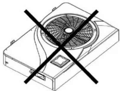
natural_image
Technical line drawing of a fan with a diagonal black cross mark (no text or symbols)Fig. 1
flowchart
graph LR
    A["Control Unit"] --> B["OUT"]
    B --> C["Flow Path with Inlet"]
    C --> D["Filtration + Pump"]
    D --> E["FROM THE POOL"]
    E --> F["Pool"]
    G["TOWARDS THE POOL"] --> H["Automated treatment system"]
    H --> I["Water Out"]
Fig. 4

natural_image
Line drawing of a front-end air conditioner unit with fan and ventilation slots (no text or symbols)
natural_image
Technical line drawing of a fan device with a black X-shaped symbol crossed out (no text or labels)Fig. 1
flowchart
graph LR
    A["Control Unit"] --> B["OUT"]
    B --> C["Flow Path with Inlet"]
    C --> D["Filtration + Pump"]
    D --> E["FROM THE POOL"]
    E --> F["Pool"]
    G["TOWARDS THE POOL"] --> H["Automated treatment system"]
    H --> I["Inlet"]
Fig. 4

natural_image
Line drawing of a small air conditioner unit with fan and ventilation duct (no text or symbols)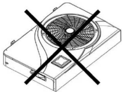
natural_image
Technical line drawing of a fan with a black X mark indicating prohibition (no text or symbols present)Fig. 1
flowchart
graph LR
    A["Control Unit"] --> B["OUT"]
    B --> C["Flow Path with Inlet"]
    C --> D["Inlet"]
    D --> E["Filtration + Pump"]
    E --> F["From the Pool"]
    F --> G["POOL"]
    G --> H["TOWARDS THE POOL"]
    H --> I["Automated treatment system"]
Fig. 4

Email: service@tip-pumpen.de

- GB EC declaration of conformity
- Table of contents
- General safety information
- Special safety instructions - Heat pump
- Danger to life due to unsuitable water temperature!
- Fire and explosion hazard due to leaking heat exchanger fins!
- Danger of injury when moving heavy devices!
- Intended use
- Technical data
- Scope of delivery
- Commissioning
- Placing of the heat pump
- Sound-absorbing underlays:
- Connecting the heat pump
- Condensation drain:
- Connecting the personal protection switch (PRCD plug)
- Switch explanation:
- Test the device before use:
- Operation
- Operating mode selection:
- GB
- Heating mode (inverter)
- Fix mode (heating only)
- ECO quiet mode
- Cooling mode (inverter)
- Heating mode (inverter):
- Fix mode (heating only):
- ECO quiet mode:
- Cooling mode (inverter):
- Setting the time on the device:
- Programming the timer:
- Activating the timer:
- Deactivating the timer:
- Status values:
- Querying of system parameters:
- Note:
- Frost protection / de-icing:
- Maintenance
- Note: All types of repairs must be carried out by qualified personnel.
- Annual maintenance:
- Winter:
- Warranty
- Please note:
- How to order spare parts
- Service
- For EC countries only
Brand : T.I.P.
Model : STEAM 35000 INV
Category : Heat pump