
H-10735 - Eye wash station Uline - Free user manual and instructions
Find the device manual for free H-10735 Uline in PDF.

User questions about H-10735 Uline
0 question about this device. Answer the ones you know or ask your own.
Ask a new question about this device
Download the instructions for your Eye wash station in PDF format for free! Find your manual H-10735 - Uline and take your electronic device back in hand. On this page are published all the documents necessary for the use of your device. H-10735 by Uline.
USER MANUAL H-10735 Uline
text_image
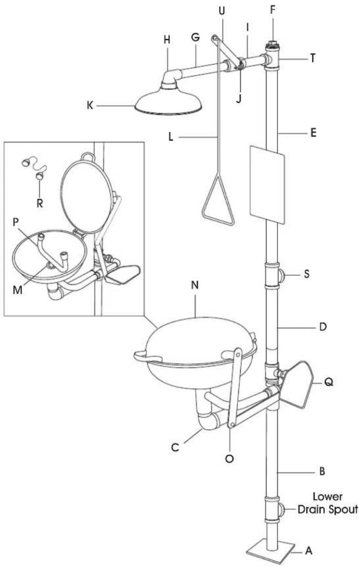
Pipe Wrench Needle Nose Pliers Plumber's Tape Pipe Joint Compound Phillips Screwdriver Drill 25/64" or 10 mm Diameter Masonry Drill Bit Hammer Eye ProtectionPARTS
| A | Base Plate |
| B | Bottom Drain Pipe |
| C | Basin Drain Set |
| D | Middle Pipe Section |
| E | Top Pipe Section |
| F | Square Head Plug |
| G | Long Shower Connection Pipe |
| H | Shower Head Elbow |
| I | Short Shower Connection Pipe |
| J | Shower Ball Valve |
| K | Shower Head |
| L | Pull Rod |
| M | Inner Basin Drain Screw |
| N | Eyewash Basin |
| O | Eyewash Bowl Arms |
| P | Twin Spray Heads |
| Q | Push Handle |
| R | Eyewash Dust Covers |
| S | Middle Horizontal Inlet |
| T | Top Vertical Inlet |
| U | Shower Ball Valve Lever |
text_image
Lower Drain Spout A B C D E F G H I J K L M P R S N Q O S TMOUNTING INSTRUCTIONS
- Verify the eyewash base plate is positioned in the desired location. Ensure the center of the base plate is at least 16" from the nearest wall. Mark the floor where holes will be drilled.

WARNING! Wear eye protection when completing step 2.
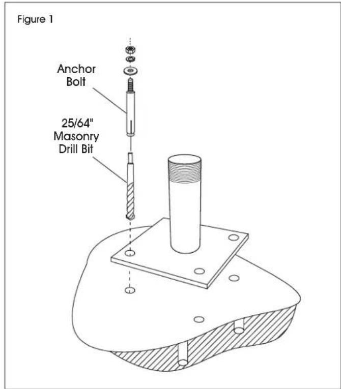
- Using a 25/64" or 10 mm diameter masonry drill bit, drill a hole approximately 2^1/2 " deep into the floor. (See Figure 1)

NOTE: For the anchor to function properly, the hole must not be larger in diameter than the anchor bolt.
text_image
Figure 1 Anchor Bolt 25/64" Masonry Drill Bit- Clean out debris and dust from inside the hole. Fully insert the anchor bolt through the mounting plate and into the hole.

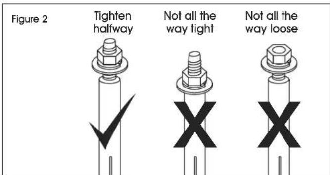
NOTE: Thread washers and nut onto anchor bolt. Nut should be tightened halfway between end of bolt and top of anchor sleeve. (See Figure 2)
text_image
Figure 2 Tighten halfway Not all the way tight Not all the way loose-
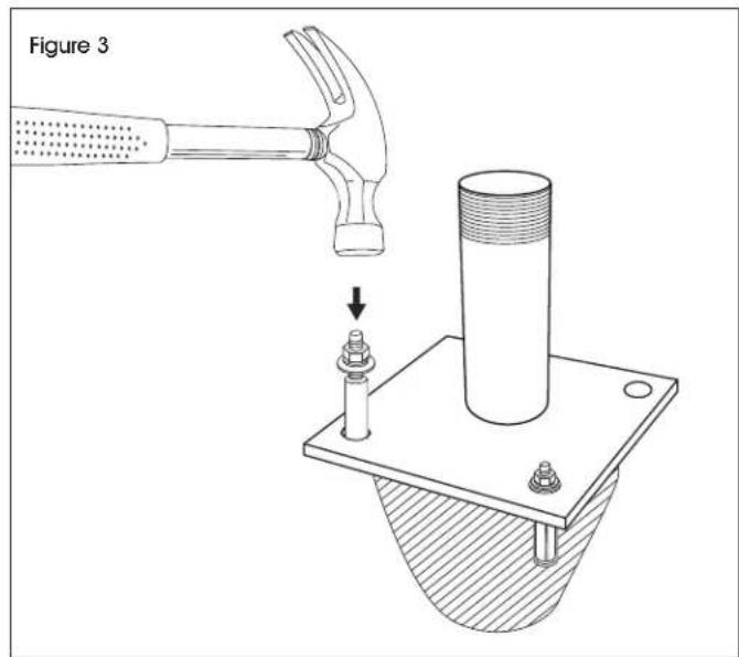
Slightly tap down the anchor bolt with a hammer if needed. Tighten the hex nut until the anchor bolt is secure. (See Figure 3)
-
Repeat for remaining anchors.
text_image
Figure 3ASSEMBLY

IMPORTANT! All pipes have tapered threads and require plumber's tape and/or joint compound to ensure watertight connection. When securing with plumber's tape, wrap tape 2-4 times around each thread for optimal seal. For best results, Uline recommends the use of plumber's tape followed by joint compound.

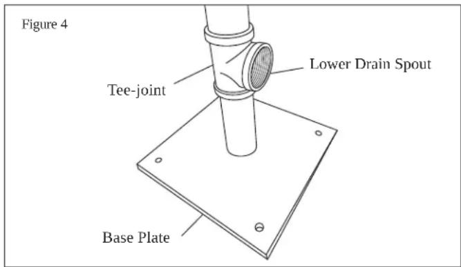
- Attach bottom drain pipe (B) to previously secured base plate (A) while ensuring lower drain spout is square with base plate. (See Figure 4)

NOTE: The tee-joint on bottom drain pipe (B) is pre-attached. It must be removed to add 2-4 layers of plumber's tape and/or joint compound in order to create a tight seal.
text_image
Figure 4 Lower Drain Spout Tee-joint Base Plate- Reattach bottom drain pipe (B) to the tee-joint.
- Attach basin drain set (C) to bottom drain pipe (B), ensuring that the basin drain set is protruding the opposite direction of the lower drain spout.
- Connect middle pipe section (D) to basin drain set (C).
- Unscrew top pipe section (E) from pre-attached top vertical (T) and middle horizontal (S) inlets. Wrap 2-4 layers of plumber's tape and/or joint compound, then reassemble with two tee-joints oriented in the opposite direction of each other.
- Connect reassembled top pipe section (E) to middle pipe section (D), ensuring that the tee-joint with the larger female inlet makes the connection with the middle pipe section (D).

NOTE: Ensure middle horizontal inlet (S) is oriented in the same direction as the lower drain spout from step 1. Ensure top vertical inlet (T) is oriented towards the basin drain set (C).
- Install the square head plug (F) at desired position on reassembled top pipe section (E).

NOTE: Water supply can be connected to top vertical inlet (T) or middle horizontal inlet (S). Install square head plug (F) into unused inlet.
- Unscrew long shower connection pipe (G) from shower head elbow (H). Set shower head elbow (H) aside for step 11.
- Unscrew short (I) and long (G) shower connection pipes from shower ball valve (J). Wrap threads with 2-4 layers of plumber's tape and/or joint compound, then reassemble.

NOTE: While disassembled, ensure shower ball valve (J) is in closed position.
- Reassemble pipes from step 9. Connect short shower connection pipe (I) to tee-joint on top vertical inlet (T).

NOTE: The shower ball valve lever (U) must be pointing upward when in the closed position.
- Connect shower head elbow (H) set aside in step 8 to long shower connection pipe (G), ensuring shower head elbow is pointing down.
- Attach shower head (K) to shower head elbow (H).
- Using pre-attached bolt and locknut, attach pull rod (L) to shower ball valve lever (U).
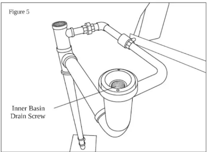
- Unscrew inner basin drain screw (M) on basin drain set (C). (See Figure 5)
text_image
Figure 5 Inner Basin Drain ScrewASSEMBLY CONTINUED
- Set eyewash basin (N) over the basin drain set (C). Use previously removed inner basin drain screw (M) to secure eyewash basin to basin drain set. Ensure basin handle points forward for final use.

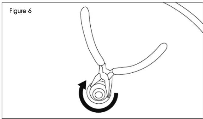
NOTE: It is recommended to tighten inner basin drain screw with needle nose pliers. (See Figure 6)
natural_image
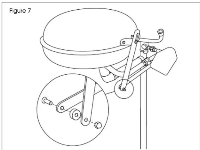
Diagram of a pliers with a curved arrow indicating rotational motion (no text or symbols)- Assemble eyewash bowl arms (O). Loosen acorn nut, insert spacer between arms and replace acorn nut. (See Figure 7)
natural_image
Technical line drawing of a mechanical device with two views: top shows a dome-shaped component, bottom shows a close-up of a mechanical lever mechanism (no text or symbols)- Thread twin spray heads (P) into eyewash basin (N) so that the twin spray heads are perpendicular to the basin drain set.

NOTE: Removing yellow eyewash dust covers (R) prior to installation may make this easier.

STOP! Performance should be verified after installation. Check for any leaks while all valves are in the closed position.

IMPORTANT! If leaking after assembly, tighten threaded connections. If leaking persists, disconnect affected connection point and add additional plumber's tape and/or joint compound.
- Activate water by pulling down on pull rod (L). Run water through shower head to flush out any impurities.

NOTE: Water flow from the shower head should be a minimum of 20 gallons/min, as per ANSI Z358.1 standards.
- Once flush is complete, push upward on pull rod (L) to close shower ball valve (J). Activate twin spray heads (P) by pressing push handle (Q) to test for proper connections.

NOTE: Water flow from the twin spray heads should be a minimum of 0.4 gallons/min, as per ANSI Z358.1 standards.
-
Mount eyewash sign in desired location using pre-attached bracket.
-
Locate inspection card in desired location using included cable tie.
MAINTENANCE
- All units should be tested on a weekly basis to clear supply lines and verify proper activation. Units must also be inspected annually to verify that they continue to meet conformance of required performance standards.
- Where freezing conditions exist, unit must be protected from freezing.
ASSEMBLY CONTINUED
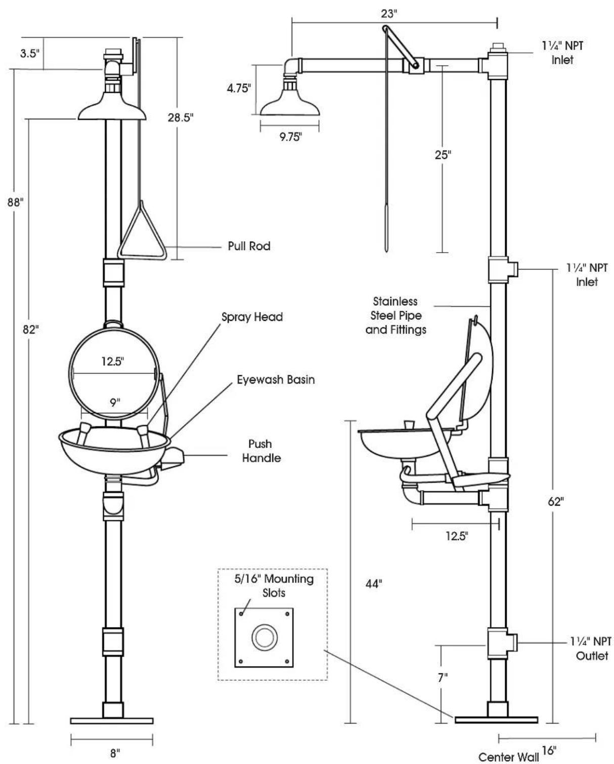
text_image
3.5" 28.5" 4.75" 9.75" 23" 1 1/4" NPT Inlet Pull Rod Spray Head Eyewash Basin Push Handle Stainless Steel Pipe and Fittings 1 1/4" NPT Inlet 12.5" 9" 62" 12.5" 44" 5/16" Mounting Slots 1 1/4" NPT Outlet 7" 8" 8" Center Wall 16"This unit complies with the requirements of ANSI Z358.1.


