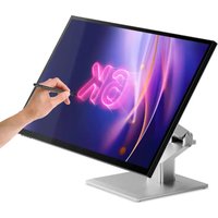
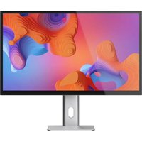
Clarity 6K Touch 32C6KPDTF - Monitor Alogic - Free user manual and instructions
Find the device manual for free Clarity 6K Touch 32C6KPDTF Alogic in PDF.


| Product Type | 6K Touch Monitor |
| Brand | Alogic |
| Model | Clarity 6K Touch 32C6KPDTF |
| Screen Size | 32 inches (16:9) |
| Native Resolution | 6016 x 3384 (6K) |
| Refresh Rate | 60 Hz |
| Panel Type | IPS |
| Backlight | ELED |
| Brightness | 400 nits (typical) |
| Contrast Ratio | 2000:1 |
| Viewing Angle | 178° horizontal / 178° vertical |
| Number of Colors | 1.07 billion |
| Touch Screen | Yes, MPP 2.0 compatible |
| Built-in Speakers | 2 x 5 W |
| Video Connectivity | 1 x DisplayPort 1.4, 2 x HDMI 2.0, 1 x USB-C (DP Alt Mode) |
| USB Connectivity | 1 x USB-C (upstream, 90W PD), 1 x USB-B (upstream), 2 x USB-A (downstream) |
| Audio Output | 1 x 3.5mm jack |
| USB PD Power Delivery | Up to 90 W |
| Dimensions (with stand) | 726 x 481 x 250 mm (W x H x D) |
| Weight | 10 kg |
| VESA Mount | 100 x 100 mm |
| Power Supply | External adapter: AC input 100-240V, 50/60 Hz; DC output 24V, 8.3A, 200W max |
| Materials | ABS, glass, aluminum |
| Special Features | Low blue light, flicker-free, PIP/PBP, HDR, image presets |
| Care and Cleaning | Use a dry, soft microfiber cloth. Do not spray liquids or use solvents. |
| Safety | Use only indoors, in a dry and ventilated area. Do not block ventilation openings. Do not disassemble. |
| Spare Parts and Repairability | No user-serviceable parts. Contact ALOGIC customer support in case of failure. |
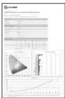
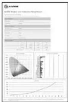
| Included Accessories | Foldable stand, USB-C cable, USB-A to B cable, DisplayPort cable, power adapter, mounting screws, color calibration report |
Frequently Asked Questions - Clarity 6K Touch 32C6KPDTF Alogic
User questions about Clarity 6K Touch 32C6KPDTF Alogic
0 question about this device. Answer the ones you know or ask your own.
Ask a new question about this device
Download the instructions for your Monitor in PDF format for free! Find your manual Clarity 6K Touch 32C6KPDTF - Alogic and take your electronic device back in hand. On this page are published all the documents necessary for the use of your device. Clarity 6K Touch 32C6KPDTF by Alogic.
USER MANUAL Clarity 6K Touch 32C6KPDTF Alogic
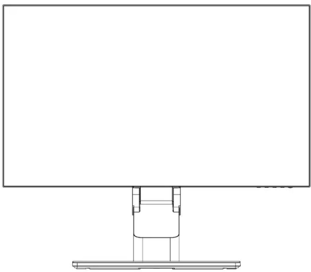
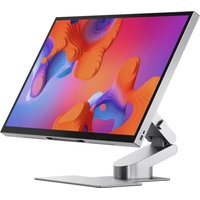
32" Touchscreen Monitor with Fold Stand
natural_image
Line drawing of a computer monitor with a stand (no text or symbols)Quick Start Guide

FAQ and Support Download macOS
Touch Drivers
Quick Start Guide
natural_image
Empty white rectangle with a thin gray border (no text or symbols)②
natural_image
Technical line drawing of a mechanical assembly with no visible text or symbols③
natural_image
Technical line drawing of a square plate with an oval recess and mounting holes (no text or symbols)4
⑤
natural_image
Line drawing of a U-shaped cable with two connectors (no text or symbols)6
natural_image
Line drawing of a U-shaped cable with two USB connectors (no text or symbols)7
8
9
natural_image
Pure diagram of a medical or laboratory setup with tubing and connector (no text or symbols)10
Package Contents
| 1 | Clarity 32" 6K Monitor |
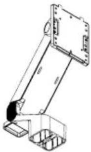
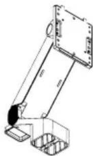
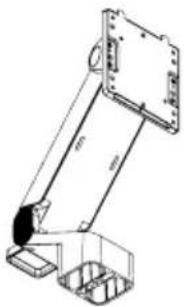
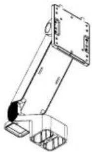
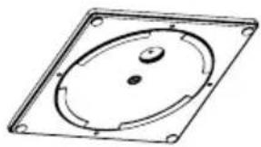
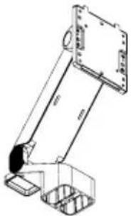
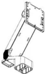
| 2 | Fold Stand Stem |
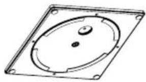
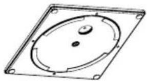
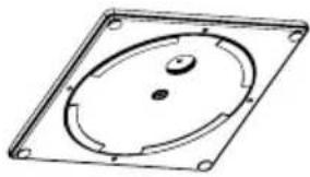
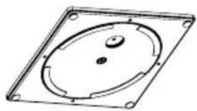
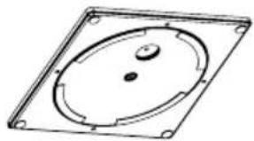
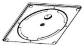
| 3 | Fold Stand Base |
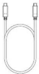
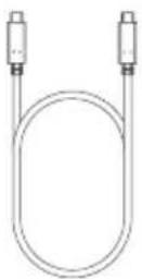
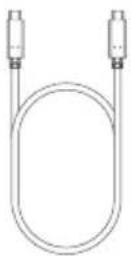
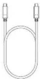
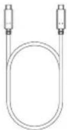
| 4 | USB-C to USB-C Cable (USB3.2 - Gen1) |
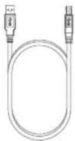
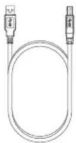
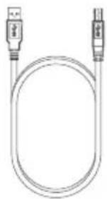
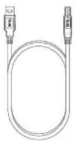
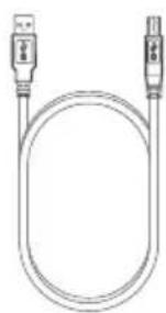
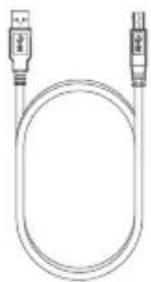
| 5 | USB-A to USB-B Cable |
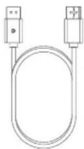
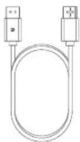
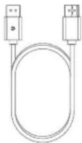
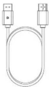
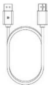
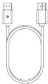
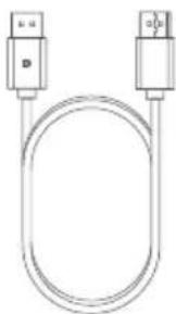
| 6 | DisplayPort to DisplayPort Cable |
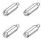
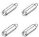
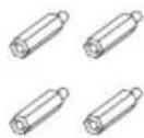
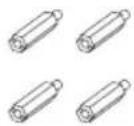
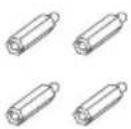
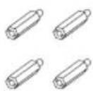
| 7 | Screws x 4 (for VESA Mounting) |
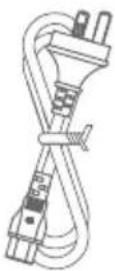
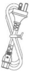
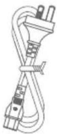
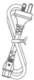
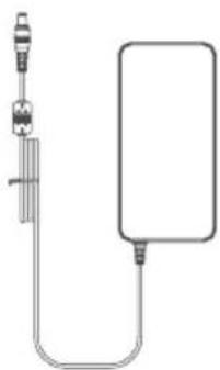
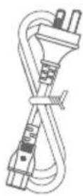
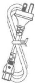
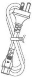
| 8 | Power Cable (AC 100-240V, 50/60Hz) |
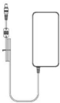
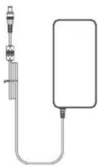
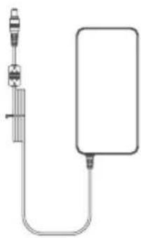
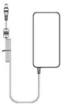
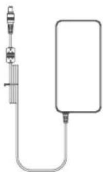
| 9 | Power Adapter |
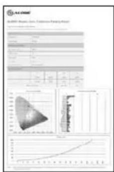
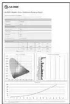
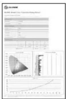
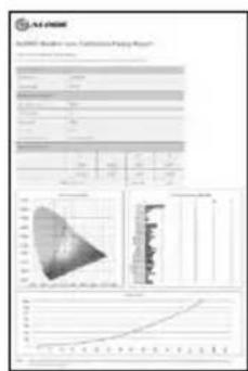
| 10 | Color Calibration Report |
Specifications
| Model 32C6KPDTF | |
| Screen Size 32" | |
| Dimensions | With Stand: 726x481x250mm (WxHxD)Without Stand: 726x428x57mm (WxHxD) |
| Weight 10kg | |
| Material ABS, Glass, Aluminium | |
| Power Adapter | Input: AC 100-240V", 50/60HzOutput: DC 24V=8.3A, 200W (Max) |
| Aspect Ratio | 16:9 |
| Backlight | ELED |
| Brightness | 400cd/m2 (Typ.), 350cd/m2(Min.) |
| Panel | IPS |
| Resolution | DP1.4: 6016x3384HDMI2.0: 6016x3384@30Hz |
| Refresh Rate 60Hz | |
| Viewing Angle 178°(H) / 178°(V) | |
| Contrast Ratio 2000:1 | |
| VESA Mounting 100 x 100mm | |
| Display Colors 1.07B | |
| Interface | 1x DP 1.4, 2x HDMI 2.0, 1x USB-C, 2x USB-A, 1x USB-B, 1x Audio Out |
| Stylus Compatibility Microsoft Pen Protocol (MPP) 2.0 | |
| Audio | Speakers: 5Wx2Audio Out: Yes |
| Low Blue Light Yes | |
| Flicker Free Yes | |
USB PD Power Delivery Up to 90W

Monitor Controls
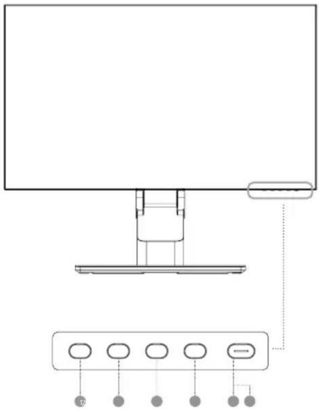
| 1 | Menu: Press to display OSD menu and enter sub-menus |
| 2 | Up/Left: Press to move Down/Left in menus |
| 3 | Down/Right: Press to move Up/Right In menus |
| 4 | Exit: Press to exit OSD menu |
| 5 | Power: Press to turn monitor on/off |
| 6 | LED Indicator and Power Button |
Indicator Light
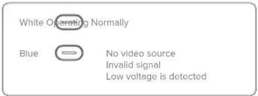
The indicator light shows steady white to indicate that the power is on and the monitor is operating normally. The steady blue light indicates that there is no video source, an invalid signal, or low voltage is detected. Please make sure that your computer is turned on and all video cables are fully plugged in or connected.
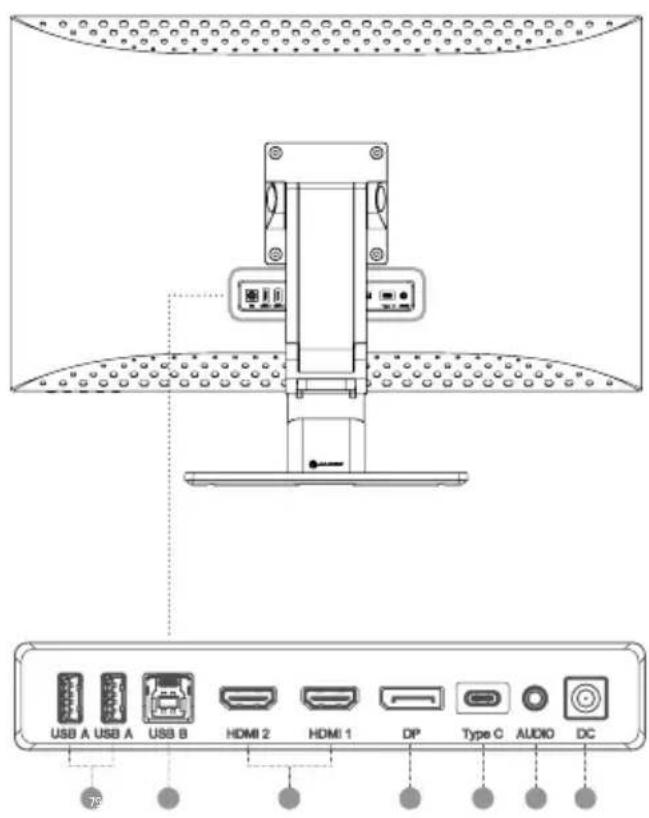
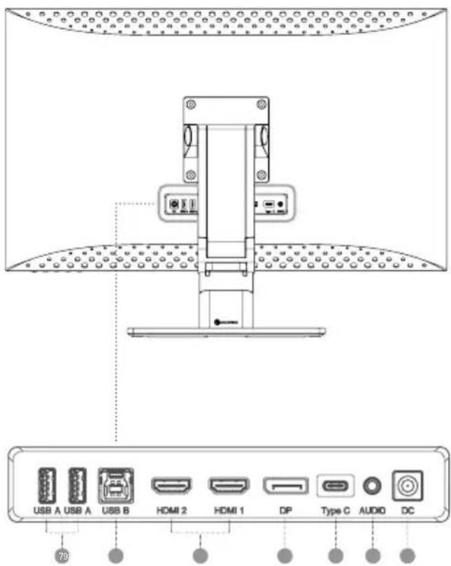
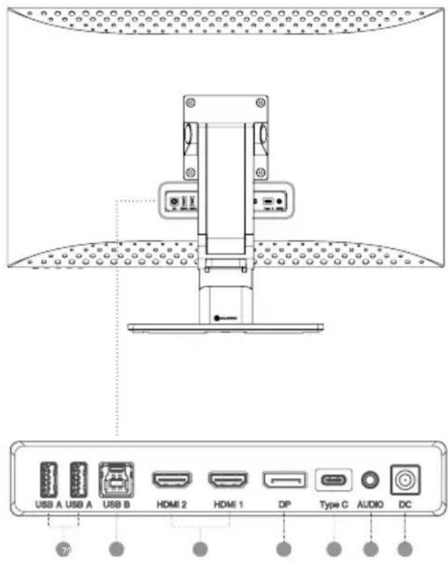
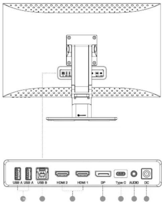
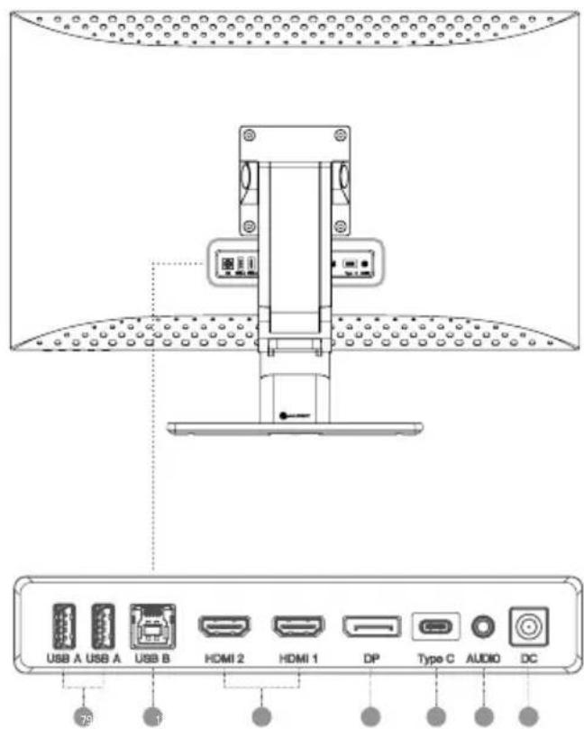
Monitor Ports
| 7 | USB-A Ports |
| 8 | USB-B Port |
| 9 | HDMI Ports |
| 10 | DisplayPort |
| 11 | USB-C Port |
| 12 | Audio Output For Headphones Or Powered Speakers |
| 13 | Power Input |

Unpacking and Assembly
Before unpacking the stand, ensure that the box is placed on a flat, clear surface.
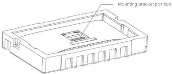
- Open the lid of the monitor box, remove the upper Styrofoam tray containing the stand and place it to one side.
- Open the soft bag that protects the monitor to reveal where the stand attaches to the rear of the monitor. Leave the monitor laying in the Styrofoam tray to avoid damaging it while installing the stand.
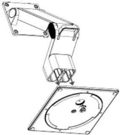
- Take care when removing the elastic band holding the Fold Stand Stem in position, as the Stem will spring open with surprising force.
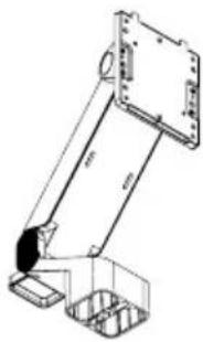
- Insert the Stand Stem into the base and use the thumbscrew beneath the stand to secure it. You may need to rotate the disc under the stand to expose the thumbscrew.
natural_image
Technical line drawing of a robotic arm and its corresponding circular component (no text or symbols)Warning:
Stand may spring open with force when safety band is removed.
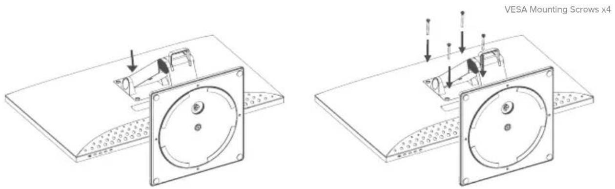
- Insert the stand into the face down monitor, and secure it with the four screws provided. Your monitor is now ready to use.
Mounting Options
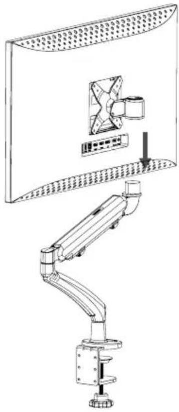
The monitor has 100 x 100mm spaced mounting holes to allow it to be mounted to any compatible 100mm VESA standard monitor arm or wall mount accessory (not included).
The mounting holes are recessed in the region on the back of the monitor where the stand attaches and are hidden by the stand when it is installed. VESA mounts cannot be used with the monitor while the stand is attached.
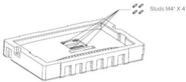
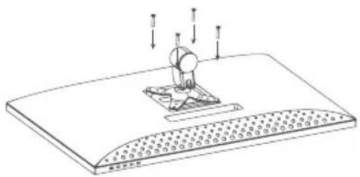
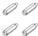
M4 threaded mounting spacers are included with the monitor which must be used when mounting the monitor to a monitor arm or other mount. Mount the monitor to a VESA mounting accessory as follows.
- Lay the monitor face down in its Styrofoam packaging tray.

Do not attempt to lay the screen on any uneven surface including soft surfaces such as carpet and seating while attaching the mounting accessory - damage to the screen may occur.
- Locate the mounting spacers in the accessory bag that comes with the monitor. With the monitor laying in its Styrofoam tray, screw in the four spacers into the holes in the recess where the stand attaches. Do not over tighten - tightening the spacers too much may cause damage to the monitor.
- Screw the VESA mounting accessory into the mounting spacers.
natural_image
Technical line drawing of a mechanical assembly with mounting base and load arrows (no text or symbols)
Do not apply pressure to the rear of the monitor while fitting the mounting accessory - downwards pressure on the screen may crack or otherwise damage it.
- Carefully lift the monitor and mounting accessory out of the tray and place into position.
natural_image
Technical line drawing of a mechanical arm assembly with a fan mounted on a wall (no text or symbols)Ensure there is 50mm clearance around all sides of the monitor when it is installed to ensure that is does not overheat.
Connecting the Monitor
Connecting the Power Cable
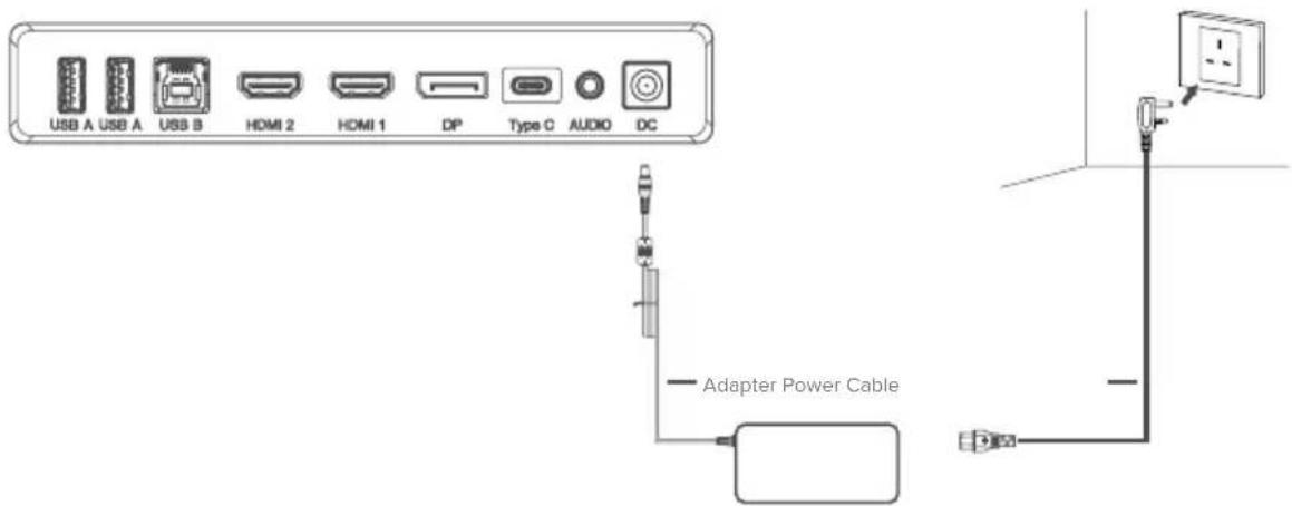
Connect the included power cable to the power connector, and then plug the other end into a wall outlet.
Connecting the Monitor
Connecting a Video Source
The monitor includes four video inputs which can be connected simultaneously. To connect a computer or other source device, plug one of the included HDMI, DisplayPort or USB-C cables into the computer and into a corresponding port on the monitor.
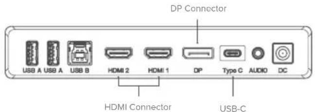
Notes:
- The USB-C connection will provide up to 90W of power to computers which support USB Power Delivery (USB PD). This allows the computer to display video on the monitor while being charged over a single cable. As a result, the USB-C connection type is the best option if your computer has this capability.
- Clarity's HDMI 2.0 ports cannot support 6K video at 60Hz. The USB-C or DisplayPort connection should be used as a first preference if the computer supports these connection types.
- Not all USB-C ports on computers support video output and/or charging using USB PD. If your computer does not show video on the monitor or start charging when connected to the monitor using USB-C, check that the USB-C port on the computer supports DisplayPort Alternate Mode video output and USB PD charging.
- Not all USB-C cables support video transfer or charging above 60W. It is recommended that you use the USB-C cable supplied with the monitor to avoid potential issues with cables that have been obtained separately.
Using the Touchscreen
- To use the touchscreen, the monitor must be connected to your computer via either its USB-C or USB-B port.
- After connecting, navigate to "USB Switch" in the "USB" sub-menu of your monitor's option menu and select either "TYPE-C" or "TYPE-B" depending on which cable you've connected.
- macOS Only: Download our Clarity Touch drivers by scanning the QR code on the manual's cover.
- The touchscreen should be automatically recognised by your computer. If not, consult our troubleshooting section below
| Symptom Solution | |
| My computer isn't reacting to my touch | • Unplug your USB cable from your computer and plug it back in. • Check you've selected the correct USB cable in your monitor's settings. • Restart your computer • Contact ALOGIC support if the above do not resolve your issue. • MacOS Only - Reinstall the touch drivers following the instructions on the Clarity Touch website by scanning the QR code on the manual's cover. |

Connecting Audio Devices
The audio port on the display only supports output devices such as headphones and speakers. It is not possible to connect microphones or other input devices to this port. Headphones with built in microphones can be connected to this port, however the microphone will not function.
To send audio from your computer to the display speakers or connected audio device, select "32C6KPDTF" as the audio destination in your computer's sound settings.
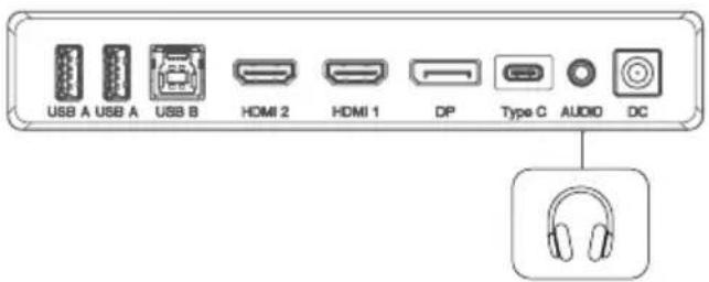
Headphones (not included)

Connecting USB Devices
The display includes two USB A ports that can be used to attach USB peripherals such as a keyboard, mouse or webcam to the computer.
In order for the computer to see devices attached to these ports, the computer must be connected to either (or both) of the USB-C and/or USB-B ports.
Notes:
- If the computer is only connected to the USB-C port on the display the ports will operate at USB 2.0 speeds because video traffic shares the USB-C cable with the USB data. This speed is sufficient for most peripherals such as keyboards, mice and webcams.
- If the computer is connected to the USB-B port on the display, the ports will operate at USB 3.0 speeds. This is preferable if using high speed storage devices such as external hard drives and USB flash drives.
OSD Menu
The OSD (On-Screen Display) lets you adjust the settings on your monitor.
-
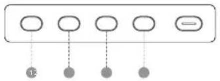
Press ① to enter the OSD menu.
-
Press 2 or 3 to browse functions.
-
Highlight the desired function, then press ① to enter the sub-menu.
- Press ② or ③ to browse sub-menus, then press ④ to highlight the desired function.
- Press ② or ③ to highlight an option, then press ④ to confirm the settings and exit the current screen.
-
Press 4 to cancel or go back to the previous menu.
-
Press 2 or 3 to adjust the setting, then press 1 to confirm your changes and exit.
flowchart
graph TD
    A[" "] --> B[" "]
    C[" "] --> D[" "]
    E[" "] --> F[" "]
    G[" "] --> H[" "]
    I["12"] -.-> A
    I -.-> C
    I -.-> E
    I -.-> G
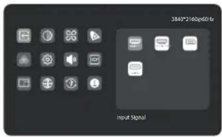
Input Signal
Switches between video inputs.
Brightness/Contrast
Adjust the Brightness, Shadow Balance and Contrast.
Video Presets
Choose between picture presets, including Standard, Reading, Movie, Night, Comfort, SRGB and Adobe modes.
Picture Settings
Adjust the monitor's Saturation, Sharpness and Gamma.
Colour Temperature
Adjust your monitor's colour temperature between Warm, Cool and User Defined.
OSD Settings
Change the transparency of the OSD menu and how long it stays on the screen.
HDR
Enables the monitor's HDR (High Dynamic Range) mode, for more vivid colours.
Not all devices and programs support HDR input, and may look too bright with this enabled.
PIP/PBP
Picture in Picture mode allows Clarity Max to display video from two sources at once.
Use this menu to select the sources and choose how you would like them to be displayed.
USB Options
You can upgrade your monitor's fi rmware via USB, prevent your computer from powering USB devices while in sleep mode, and switch which USB port (C or B) Clarity Max is using for non-video data.
Audio
You can mute or adjust the volume of the monitor's speakers.
Language
Set OSD language.
Reset
Reset your monitor to factory default settings.
Troubleshooting
| Symptom Solution | |
| The power button does not light up when pressed | · Verify that the mains power cord is securely attached to the power adapter, is connected to a power outlet and the power outlet is switched on.· Verify that the power adapter is securely connected to the rear of the monitor. |
| The power button lights up, but nothing is displayed on the screen | · Disconnect the power adapter from the Monitor and reconnect in 2-3 minutes.· Contact ALOGIC Support if the points above do not work. |
| Monitor does not show HDMI or DisplayPort video from the computer | · Check that an appropriate video cable is connected between the computer and display and the correct input is selected on the monitor.· Check your computer's settings to verify that it is detecting the monitor and is outputting video to it. |
| Monitor does not show USB-C video from the computer | · Verify that you are using the USB-C cable that came with the monitor.· Check your computer's settings to verify that it is detecting the monitor and is outputting video to it.· Check that the USB-C port on your computer that the monitor is connected to supports video output using DisplayPort Alternate Mode (DP Alt. Mode). |
| Laptop computer does not charge when connected to the monitor using USB-C | · Verify that the USB-C port on your computer supports charging using the USB Power Delivery (USB-PD) standard.· Some laptops require more than 90W of power to charge. These tend to be high end graphics and gaming focused computers.· If necessary, connect the power adapter that came with the computer to your laptop in addition to the USB-C cable that is connected to the monitor. |
Warnings
- Only use the monitor indoors in dry locations. Do not use the monitor in damp places or near water sources such as in bathrooms and kitchens.
- Store and use in a cool, dry, ventilated place. Do not place close to heat sources or in direct sunlight.
- Ensure that the equipment is installed on a flat, stable surface. If placed on an uneven or unsteady surface the monitor may fall and be damaged, cause personal injury or damage other items.
- It is normal for the device to be slightly warm to touch during operation. Provide adequate ventilation and do not cover the device while in operation.
- Do not cover or block the ventilation holes on the rear cover of the monitor. Do not use on a bed, sofa, blanket or similar where the monitor may fall over or become covered.
- The acceptable electrical supply voltage and frequency ranges are indicated on the label on the rear cover of the monitor. Do not connect the monitor to power sources which fall outside these limits.
- If the device will not be used for weeks or months, it is recommended that the power be disconnected to save energy and protect the equipment from damage caused by lightning strike induced power surges if a thunderstorm occurs.
- Do not insert foreign objects into the ventilation holes in the cover of the monitor as damage, fire or electric shock could occur.
• The monitor contains no user serviceable parts. Disassembling or attempting to repair this product yourself will void the warranty and expose you to the risk of electric shock. If you suspect a fault with the device, please contact the seller you purchased the product from or ALOGIC after sales support for assistance. - Do not use the product if it becomes damaged as this could pose a risk of causing damage to connected devices and expose you to electric shock.
- Do not crush, cut, pull or twist the mains power cord excessively. If the power cord becomes damaged do not use the product until a replacement power cord can be obtained. Using a damaged power cord may result in electric shock.
- Do not spray liquids on the monitor. Do not use chemicals such as solvents on the surface of the monitor. Clean the monitor only by wiping with a clean, dry, soft, scratch-avoiding microfibre cloth.
- Disassembling or failing to properly use and care for your device will void the warranty on the product.
• ALOGIC bears no responsibility for damage to the device or incidental damages arising from improper use or lack of care and is not liable for repair/replacement of the device or other damages in these circumstances.
①
natural_image
Empty white rectangle with a thin gray border (no text or symbols)②
natural_image
Technical line drawing of a mechanical arm with mounting flanges and a base (no text or symbols)3
natural_image
Technical line drawing of a square mechanical component with an oval recess and mounting holes (no text or symbols)4

⑤
natural_image
Line drawing of a U-shaped USB cable with two connectors (no text or symbols)6
natural_image
Line drawing of a U-shaped cable with two connectors (no text or symbols)7
8
⑨
natural_image
Simple line drawing of a medical or laboratory device with tubing and connector (no text or symbols)10
Packungsinhalt
| 1 | Clarity 32" 6K Monitor |
| 2 | Ständerstiel |
| 3 | Standfuß |
| 4 | USB-C zu USB-C Kabel (USB 3.2 - Gen 1) |
| 5 | USB-A zu USB-B Kabel |
Kontrolle
natural_image
Technical line drawing of a robotic arm and a circular base component (no text or symbols)natural_image
Technical line drawing of a mechanical assembly with a base plate and mounting bracket (no text or symbols)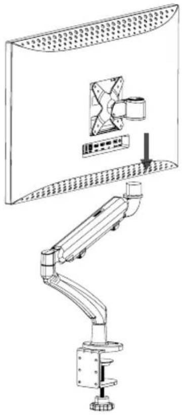
natural_image
Technical line drawing of a mechanical arm assembly with a fan mounted on a wall (no text or symbols)
Eingangssignal
natural_image
Empty white rectangle with a thin gray border (no text or symbols)②
natural_image
Technical line drawing of a robotic arm with mounting bracket and base components (no text or symbols)③
natural_image
Technical line drawing of a circular mechanical component with mounting holes and central hole (no text or symbols)4
⑤
natural_image
Line drawing of a U-shaped cable with two connectors (no text or symbols)6
natural_image
Line drawing of a U-shaped cable with two USB connectors (no text or symbols)7
8
9
natural_image
Pure diagram of a medical or laboratory setup with tubing and connector (no text or symbols)10
Controles del monitor
natural_image
Technical line drawing of a robotic arm and its corresponding circular component (no text or symbols)natural_image
Diagram of a mechanical device with a base and mounting plate, showing force arrows (no text or symbols)
natural_image
Technical line drawing of a mechanical arm assembly with a monitor and fan component (no text or symbols)natural_image
Empty white rectangle with a thin gray border (no text or symbols)2
natural_image
Technical line drawing of a mechanical arm or support structure with no visible text or symbols③
natural_image
Technical line drawing of a square plate with an oval recess and central dot (no text or symbols)④
⑤
natural_image
Line drawing of a U-shaped cable with two connectors (no text or symbols)6
natural_image
Line drawing of a U-shaped cable with two connectors (no text or symbols)7
8
9
natural_image
Simple line drawing of a medical or laboratory device with a coiled tube and connector (no text or symbols)10
line
| Time | Value | |---|---| | 0 | 0 | | 1 | 0 | | 2 | 0 | | 3 | 0 | | 4 | 0 | | 5 | 0 | | 6 | 0 | | 7 | 0 | | 8 | 0 | | 9 | 0 | | 10 | 0 | | 11 | 0 | | 12 | 0 | | 13 | 0 | | 14 | 0 | | 15 | 0 | | 16 | 0 | | 17 | 0 | | 18 | 0 | | 19 | 0 | | 20 | 0 | | 21 | 0 | | 22 | 0 | | 23 | 0 | | 24 | 0 | | 25 | 0 | | 26 | 0 | | 27 | 0 | | 28 | 0 | | 29 | 0 | | 30 | 0 | | 31 | 0 | | 32 | 0 | | 33 | 0 | | 34 | 0 | | 35 | 0 | | 36 | 0 | | 37 | 0 | | 38 | 0 | | 39 | 0 | | 40 | 0 | | 41 | 0 | | 42 | 0 | | 43 | 0 | | 44 | 0 | | 45 | 0 | | 46 | 0 | | 47 | 0 | | 48 | 0 | | 49 | 0 | | 50 | 0 | | 51 | 0 | | 52 | 0 | | 53 | 0 | | 54 | 0 | | 55 | 0 | | 56 | 0 | | 57 | 0 | | 58 | 0 | | 59 | 0 | | 60 | 0 | | 61 | 0 | | 62 | 0 | | 63 | 0 | | 64 | 0 | | 65 | 0 | | 66 | 0 | | 67 | 0 | | 68 | 0 | | 69 | 0 | | 70 | 0 | | 71 | 0 | | 72 | 0 | | 73 | 0 | | 74 | 0 | | 75 | 0 | | 76 | 0 | | 77 | 0 | | 78 | 0 | | 79 | 0 | | 80 | 0 | | 81 | 0 | | 82 | 0 | | 83 | 0 | | 84 | 0 | | 85 | 0 | | 86 | 0 | | 87 | 0 | | 88 | 0 | | 89 | 0 | | 90 | 0 | | 91 | 0 | | 92 | 0 | | 93 | 0 | | 94 | 0 | | 95 | 0 | | 96 | 0 | | 97 | 0 | | 98 | 0 | | 99 | 0 | | Note: The data is in a table format for the years ended September. The values are estimated based on the provided code. There is no additional data series present in the image. The values are estimated based on the provided code.Contenu du paquet
natural_image
Technical line drawing of a robotic arm and its corresponding circular component (no text or symbols)natural_image
Technical line drawing of a rectangular electronic component with internal structure and mounting holes (no text or symbols)natural_image
Technical line drawing of a mechanical assembly with mounting base and force arrows (no text or symbols)
natural_image
Technical line drawing of a mechanical arm assembly with a fan and control panel (no text or symbols)natural_image
Empty white rectangle with a thin gray border (no text or symbols)②
natural_image
Technical line drawing of a mechanical assembly with no visible text or symbols③
natural_image
Technical line drawing of a square plate with an oval recess and central dot (no text or symbols)④
5
natural_image
Line drawing of a U-shaped USB cable with two connectors (no text or symbols)6
natural_image
Line drawing of a U-shaped cable with two connectors (no text or symbols)7
8
9
natural_image
Pure diagram of a medical or laboratory device with tubing and connector (no text or symbols)10
Package Contents
| 1 | 32" Clarity 6K Monitor |
| 2 | Gambo del supporto |
| 3 | Base del supporto |
| 4 | Cavo da USB-C a USB-C (USB3.2 - Gen1) |
| 5 | Cavo da USB-A a USB-B |
Controlli del Monitor
natural_image
Technical line drawing of a robotic arm and its corresponding circular component (no text or symbols)Attenzione:
natural_image
Technical line drawings of mechanical components on two views (no text or symbols)natural_image
Diagram of a mechanical assembly with a rotating component and mounting base (no text or symbols)
natural_image
Technical line drawing of a mechanical arm assembly with a fan and control panel (no text or symbols)natural_image
Empty white rectangle with a thin gray border (no text or symbols)②
natural_image
Technical line drawing of a mechanical assembly with no visible text or symbols③
natural_image
Technical line drawing of a circular component mounted on a square base (no text or symbols)4

⑤
natural_image
Line drawing of a U-shaped cable with two connectors (no text or symbols)6
natural_image
Line drawing of a U-shaped cable with two USB connectors (no text or symbols)7
8
9
natural_image
Pure electrical circuit lines without any symbols10
パッケージ内容
モニターコントロール
natural_image
Technical line drawing of a robotic arm and its corresponding circular component (no text or symbols)警告:
natural_image
Technical line drawings of a mechanical assembly with mounting flanges and a circular component, showing no text or symbols.取り付けオプション
natural_image
Diagram of a mechanical assembly with a rotating component and force arrows, no text or symbols present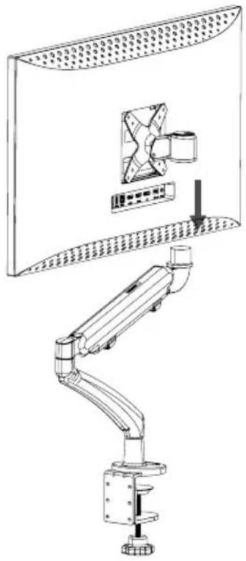
natural_image
Technical line drawing of a mechanical arm assembly with a fan mounted on a wall (no text or symbols)
ضوء المؤشر
natural_image
Empty white rectangle with a thin gray border (no text or symbols)4
5

natural_image
Pure diagram of a U-shaped cable with two connectors (no text or symbols)8
9

natural_image
Pure diagram of a medical or laboratory device with tubing and connector (no text or symbols)2
natural_image
Technical line drawing of a mechanical arm or robotic arm with no visible text or symbols3
natural_image
Technical drawing of a circular mechanical component with mounting holes and central hole (no text or symbols)6
natural_image
Line drawing of a U-shaped cable with two connectors (no text or symbols)7
10
محتويات الحزمة
natural_image
Technical line drawing of a mechanical arm assembly with a mounted device and panel (no text or symbols)natural_image
Line drawing of a rectangular building interior with a crane and structural supports (no text or symbols)natural_image
Diagram of a mechanical assembly with a central component and surrounding textured surface (no text or symbols)natural_image
Technical line drawing of a mechanical assembly with no visible text or symbolsnatural_image
Technical line drawing of a mechanical assembly with a component and mounting plate (no text or symbols)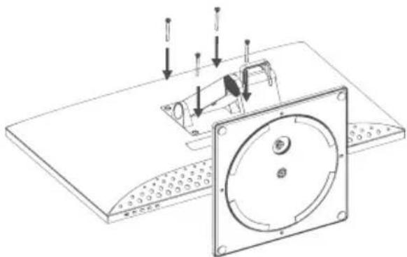
natural_image
Technical line drawing of a mechanical assembly with mounting plate and circular component (no text or symbols)FCC Compliance Statement
This device complies with Part 15 of the FCC Rules. Operation is subject to the following two conditions:
(1) this device may not cause harmful interference, and (2) this device must accept any interference received, including interference that may cause undesired operation.
Changes or modifications not expressly approved by the party responsible for compliance could void the user's authority to operate the equipment.
This equipment has been tested and found to comply with the limits for a Class B digital device, pursuant to Part 15 of the FCC Rules. These limits are designed to provide reasonable protection against harmful interference in a residential installation. This equipment generates, uses and can radiate radio frequency energy and, if not installed and used in accordance with the instructions, may cause harmful interference to radio communications. However, there is no guarantee that interference will not occur in a particular installation.
If this equipment does cause harmful interference to radio or television reception, which can be determined by turning the equipment of and on, the user is encouraged to try to correct the interference by one or more of the following measures:
• Reorient or relocate the receiving antenna.
- Increase the separation between the equipment and receiver.
- Connect the equipment into an outlet on a circuit different from that to which the receiver is connected.
- Consult the dealer or an experienced radio/TV technician for help.
Responsible Party - U.S. Contact Information
ALOGIC USA LLC
37524 Marsten Dr,
Newark CA 94560, USA
EU Declaration of Conformity
Hereby, ALOGIC Corporation declares that this product is in compliance with Directive 2014/53/EU. The full text of the EU declaration of conformity is available at the following internet address by clicking on the Compliance Documentation link at: www.alogic.co
- Indicator Light
- Unpacking and Assembly
- Mounting Options
- Connecting the Monitor
- Notes:
- Using the Touchscreen
- Connecting Audio Devices
- Connecting USB Devices
- OSD Menu
- Input Signal
- Brightness/Contrast
- Video Presets
- Picture Settings
- Colour Temperature
- OSD Settings
- HDR
- PIP/PBP
- USB Options
- Audio
- Language
- Reset
- Warnings
- Eingangssignal
- Controles del monitor
- Attenzione:
- パッケージ内容
- モニターコントロール
- 取り付けオプション
- ضوء المؤشر
- FCC Compliance Statement
- EU Declaration of Conformity
Brand : Alogic
Model : Clarity 6K Touch 32C6KPDTF
Category : Monitor