KD8178BD - Fridge Atag - Free user manual and instructions
Find the device manual for free KD8178BD Atag in PDF.

User questions about KD8178BD Atag
0 question about this device. Answer the ones you know or ask your own.
Ask a new question about this device
Download the instructions for your Fridge in PDF format for free! Find your manual KD8178BD - Atag and take your electronic device back in hand. On this page are published all the documents necessary for the use of your device. KD8178BD by Atag.
USER MANUAL KD8178BD Atag
Operating and installation instructions
Combined fridge-freezer for integrated use, door-on-door
natural_image
Line drawing of an open refrigerator with multiple compartments and doors (no text or symbols)KD8178BD
700003816000
ATAG
Inhoudsopgave
text_image
Diagram of an open refrigerator with numbered compartments and food items, including a rose dish and bottles.text_image
Technical diagram showing exploded view and assembly of a device with numbered components and directional arrows indicating motion or movement.text_image
Architectural floor plan with numbered rooms and furniture placement, likely for architectural or engineering design.natural_image
Technical line drawing of a mechanical assembly with no visible text or symbolsFig. 8

text_image
Technical diagram showing mechanical assembly with numbered parts 34 and 35, likely part of a device or assembly.Fig. 9
Bij 16 mm dikke meubel-
wanden= 568 mm brede nis:
text_image
Technical diagram showing labeled components of a mechanical assembly with numbered partsFig. 17
text_image
30 31 32 8 31 33 Fig. 18text_image
Technical diagram showing a mechanical assembly with labeled components and a magnified inset of a wooden structure with coordinate axes (X, Y, Z).Fig. 20
text_image
Technical diagram showing a mechanical assembly with numbered components and a zigzag arrow indicating direction or force.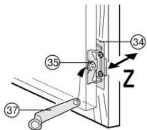
text_image
Technical diagram showing labeled mechanical components with numbered parts and directional arrowsFig. 22
text_image
Technical diagram showing a mechanical assembly with labeled parts, including numbered callouts 32 and 37.Fig. 23
text_image
Technical diagram of a device with numbered components and labeled parts, likely for assembly or maintenance instructions.Fig. 24
text_image
Technical diagram showing mechanical assembly with labeled components and directional arrows indicating motion or forcetext_image
Diagram showing a hand holding test tubes with numbered arrows indicating measurement or process stepstext_image
Technical diagram illustrating mechanical assembly steps with labeled components and directional arrowsFig. 25
natural_image
Two-panel illustration showing hands reading a document with a pen (no text or symbols visible)natural_image
Diagram of a refrigerator interior with upward and downward arrows indicating airflow or movement (no text or symbols)5.6.8 Info-systeem
natural_image
Line drawing of a wooden drawer with two compartments (no text or symbols)6 Onderhoud
natural_image
Diagram of a storage or lifting mechanism with a downward arrow indicating compression or clearance (no text or symbols present)Onderdelen:
text_image
Diagram of an open refrigerator with numbered compartments and food items, showing interior shelves and storage areas.Fig. 1
text_image
Technical diagram of a refrigerator with numbered components and directional arrows indicating movement or assembly.text_image
Architectural floor plan with numbered rooms and structural annotationsnatural_image
Illustration of a hand holding a thin wire with a small hook attached, labeled 'Fig. 7' (no text or symbols on the diagram itself)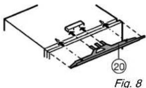
text_image
20 Fig. 8text_image
Technical diagram showing two mechanical assembly steps with bolted components and numbered callouts (28)Fig. 15
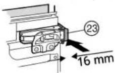
Fig. 10
text_image
53 51 50Fig. 11
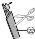
Fig. 12
text_image
53 50 51 29Fig. 16
Griffseitig oben:
text_image
Technical diagram showing labeled components of a mechanical assembly with numbered partsFig. 17
text_image
Technical diagram showing a mechanical assembly with labeled components and a magnified inset of a wooden structure with coordinate axes X, Y, Z.Fig. 20
text_image
Technical diagram showing a mechanical assembly with numbered components and directional arrows indicating motion or force.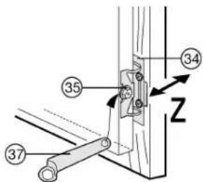
text_image
Technical diagram showing labeled mechanical components with numbered parts and directional arrowsFig. 22
text_image
Technical diagram showing assembly steps with numbered components, including a switch and toolFig. 23
text_image
Diagram illustrating a mechanical assembly or repair process with labeled components and directional arrows indicating movement.text_image
Diagram showing a hand holding a tray with three labeled parts (1, 2, 3) and directional arrows indicating movement or force.natural_image
Two-panel illustration showing hands reading a document with arrows indicating motion (no text or symbols)natural_image
Diagram of a refrigerator interior showing airflow direction with arrows (no text or symbols)5.6.8 Info-System

natural_image
Line drawing of a wooden drawer with two compartments (no text or symbols)6 Wartung
natural_image
Diagram of a storage rack with two compartments and an arrow indicating direction (no text or symbols)Ausstattungsteile:
text_image
① Index / Ⅲ Service-Nr./No. Service ② Cement / Class Class / Class Ap-Type: AP Type AP Type: AP Type Btuition/Not - Stone Capacity Motive Band Capacity (GB) Dachenvoltsgen / Freezing Capacity Procedural / Coupling / Coupling ③ R 800a: 300 g HCL: 100000000000000000000000000000000000000000000000000000000000000000000000000000000000000000000 ③Fig. 27
1 Appliance at a glance.... 28
1.1 Description of appliance and equipment.... 28
1.2 Range of appliance use.... 28
1.3 Conformity....29
1.4 Saving energy....29
2 General safety information.... 29
3 Controls and displays.... 29
3.1 Operating and control elements.... 29
3.2 Temperature display.... 30
4 Putting into operation.... 30
4.1 Transporting the appliance.... 30
4.2 Installing the appliance.... 30
4.3 Changing the door hinges.... 30
4.4 Installation....31
4.5 Disposing of packaging.... 35
4.6 Connecting the appliance.... 35
4.7 Switching on the appliance.... 35
5 Control.... 35
5.1 Brightness of the temperature display.... 35
5.2 Child proofing.... 35
5.3 Door alarm.... 36
5.4 Temperature alarm.... 36
5.5 Refrigerator compartment 36
5.6 Freezer compartment.... 37
6 Maintenance.... 38
6.1 Defrosting with NoFrost 38
6.2 Cleaning the appliance.... 38
6.3 Customer service.... 39
7 Malfunction.... 39
8 Decommissioning.... 40
8.1 Switching off the appliance.... 40
8.2 Taking the appliance out of service.... 40
9 Disposing of the appliance.... 40
The manufacturer works constantly on the further development of all the types and models. Therefore please understand that we have to reserve the right to make design, equipment and technical modifications.
To get to know all the benefits of your new appliance, please read the information contained in these instructions carefully. The instructions apply to several models. Differences may occur. Text relating only to specific appliances is marked with an asterisk (*).
Instructions for action are marked with a ▶, the results of action are marked with a ▷
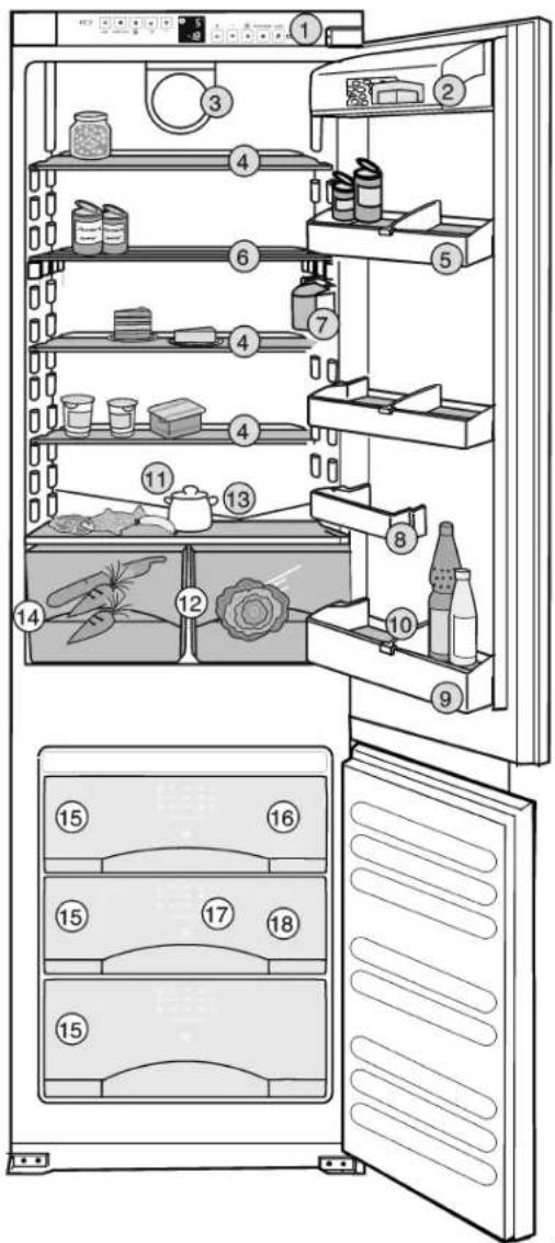
1 Appliance at a glance
1.1 Description of appliance and equipment
Note
▶ Place food inside the appliance as shown in the diagram. This allows the appliance to save energy during operation.
▶ Shelves, drawers and baskets are arranged for optimum energy efficiency on delivery.
text_image
Diagram of an open refrigerator with numbered compartments and food items, showing interior shelves and storage areas.(1) Operating and control elements
(2) Butter and cheese compartment
(3) Fan (12) Vegetable bin
(4) Relocatable shelf
(5) Jar rack
(6) Sectioned shelf
(7) Interior light
(8) Storage rack
(9) Storage rack for tall bottles
(10) Bottle holder
(11) Coldest zone
(13) Drain opening
(14) Type plate
(15) Freezer drawer
(16) Cold storage accumulator
(17) Information system
(18) VarioSpace
1.2 Range of appliance use
The appliance is suitable solely for cooling food in a domestic environment or similar. This includes use in, for example
- in staff kitchenettes, bed and breakfast establishments,
- by guests in country homes, hotels, motels and other forms of accommodation,
- in catering and similar services in the wholesale trade
Use the appliance solely as is customary within a domestic environment. All other types of use are inadmissible. The appliance is not suitable for storing and cooling medicines, blood plasma, laboratory preparations or similar substances and products covered by the 2007/47/EC Medical Devices Directive. Misuse of the appliance can result in the stored products
suffering harm or perishing. Furthermore, the appliance is not suitable for operation in potentially explosive atmospheres.
The appliance is set to operate within specific ambient temperature limits according to its climate rating. The correct climate rating for your appliance is indicated on the type plate.
Note
▶ Compliance with the ambient temperatures indicated is required, otherwise the cooling performance is reduced.
| Climate rating | for ambient temperatures of |
| SN 10 °C to 32 °C | |
| N 16 °C to 32 °C | |
| ST 16 °C to 38 °C | |
| T 16 °C to 43 °C |
1.3 Conformity
The refrigerant circuit has been tested for leaks. When installed, this appliance complies with the relevant safety provisions and EC directives 2006/95/EC and 2004/108/EC.
1.4 Saving energy
- Always ensure good ventilation. Do not cover ventilation openings or grille.
- Always keep fan louvres clear.
- Do not place appliance in areas of direct sunlight or next to a stove, heater or similar object.
- The energy consumption depends on the installation conditions, e.g. the ambient temperature (see 1.2).
- Keep the time the appliance is open to a minimum.
- The lower the temperature setting, the higher the power consumption.
- Store food logically. (see Appliance at a glance).
- Ensure that all food is well packed and covered for storage. This will prevent frost from forming.
- Remove food as needed in order that it does not warm too much.
- First cool warm food to room temperature before storing it.
- Defrost frozen food in the refrigerator.
- Empty and switch off refrigerating unit for longer vacation periods.
2 General safety information
Danger for the user:
- This appliance is not designed for persons (including children) with physical, sensory or mental impairment or persons not having sufficient experience and knowledge, unless they are instructed in the use of the appliance and are initially supervised by a person responsible for their safety. Keep children under supervision to ensure they do not play with the appliance.
- In case of a fault, pull out the mains plug (not by pulling the connecting cable) or switch off the fuse.
- Have any repairs to or intervention in the appliance, and any change of the mains power cable, carried out by the customer service only or by other specialised personnel trained for the purpose.
- When disconnecting the appliance from the supply, always take hold of the plug. Do not pull the cable.
- Install and connect the appliance only as instructed.
- Please keep these instructions in a safe place and pass them on to any subsequent owners.
- Special-purpose lamps (incandescent lamps, LEDs, fluorescent tubes) in the appliance serve to illuminate the appliance interior and are not suited for room illumination.
Fire hazard:
- The refrigerant R 600a is environmentally friendly but flammable. Escaping refrigerant may ignite.
- Do not damage the refrigerant circuit pipes.
- Do not allow naked flames or ignition sources to enter the appliance.
- Do not use any electrical appliances in the interior (e.g. steam cleaners, heaters, ice cream maker etc.).
-
If refrigerant escapes: eliminate naked flames or sources of ignition from the vicinity. Pull out the power plug. Venti-late the area well. Notify customer service.
-
Do not store explosives or sprays using combustible propellants such as butane, propane, pentane, etc. in the appliance. Respective spray cans can be identified by reference to the contents printed on the can or by a flame symbol. Gases possibly escaping may ignite due to electrical components.
- Only store high-percentage alcohol in tightly sealed, upright containers. Alcohol possibly escaping may ignite due to electrical components.
Danger of tipping and falling:
- Do not misuse the plinth, drawers, doors etc. as a step or for support. This applies particularly to children.
Danger of food poisoning:
- Do not consume food which has been stored too long.
Danger of frostbite, numbness and pain:
- Avoid lasting skin contact with cold surfaces or refrigerated/frozen food or take protective steps, e.g. wear gloves. Do not consume ice cream, water ice or ice cubes immediately and do not consume them too cold.
Please observe the specific information in the other sections:
| DANGER identifies a situation involving direct danger which, if not obviated, may result in death or severe bodily injury. | ||
| WARNING | identifies a dangerous situation which, if not obviated, may result in death or severe bodily injury. | |
| CAUTION | identifies a dangerous situation which, if not obviated, may result in minor or medium bodily injury. | |
| NOTICE | identifies a dangerous situation which, if not obviated, may result in damage to property. | |
| Note | identifies useful information and tips. | |
3 Controls and displays
3.1 Operating and control elements

text_image
⑦ FAN FAST-COOL ON OFF + - 5 ° -18 ⑬ ⑭ ⑮ ⑯ ⑰ ⑱ ⑲ ⑳ ⑴ ⑵ ⑶ ⑦ ON OFF FAST-FREEZE ALARMFig. 2
(1) Alarm button
(8) Child lock symbol
(2) Fast Freeze button (9) - setting button, refrigerator compartment
(3) On/Off button, freezer compartment
(10) + setting button, refrigerator compartment
(4) - setting button, freezer compartment
(11) On/Off button, refrigerator compartment
(5) + setting button, freezer compartment
(12) Fast Cool button
(6) Freezer compartment temperature display
(13) Fan button
(7) Refrigerator compartment temperature display
3.2 Temperature display
The following are displayed in normal operation:
- the warmest freezing temperature
- the average cooling temperature
The freezer compartment temperature display flashes:
- the temperature setting is being changed
- after switch-on the temperature is not yet cold enough
- the temperature has risen several degrees
Dashes flash in the display:
- the freezer temperature is above 0 °C.
The following displays indicate malfunction. Possible causes and corrective action (see Malfunction).
- nA
- F0 to F5
4 Putting into operation
4.1 Transporting the appliance

CAUTION
Risk of injury and danger of damage as a result of incorrect transport!
▶ Transport the appliance in a packed condition.
▶ Transport the appliance upright.
▶ Do not transport the appliance without assistance.
4.2 Installing the appliance
In the event that the appliance is damaged, contact the supplier immediately before connecting to the mains.
The floor at the site must be flat and level.
Do not install the appliance in a location where it is exposed to direct radiation of the sun, next to a cooker, heater and similar.
Do not install the appliance without assistance.
Standard EN 378 specifies that the room in which you install your appliance must have a volume of 1m^-2 per 8g of R 600a refrigerant used in the appliance. If the room in which the appliance is installed is too small, a flammable gas-air mixture may form in the event of a leakage in the refrigeration circuit. The quantity of refrigerant used in your appliance is indicated on the type plate on the inside of the appliance.
Fit the appliance in stable kitchen units only.
The following ventilation gaps must be observed:
☐ The depth of the ventilation channel at the rear of the unit must be at least 38 mm.
☐ There must be a ventilation space of at least 200 cm ^2 in the plinth and at the top of the unit.
□ Basically the principle applies: the larger the ventilation space, the more energy-saving the appliance is in operation.

WARNING
Fire hazard due to dampness!
If live parts or the mains lead become damp this may cause short circuits.
The appliance is designed for use in enclosed areas. Do not operate the appliance outdoors or in areas where it is exposed to splash water or damp conditions.

WARNING
Fire hazard due to refrigerant!
The refrigerant R 600a is environmentally friendly but flammable. Escaping refrigerant may ignite.
▶ Do not damage the piping of the refrigeration circuit.

WARNING
Fire hazard and danger of damage!
▶ Do not place appliances emitting heat e.g. microwaves, toasters etc. on the appliance!
▶ Detach the connecting cable from the rear of the appliance, removing the cable holder at the same time because otherwise there will be vibratory noise!
After installation:
▶ Remove the protective film from the decorative trims and drawer fronts.
▶ Remove all transit supports.
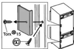
▶ Unscrew the red transport lock. Close the vacated retaining hole using the stopper (60).
text_image
Torx® 15▶ Dispose of packaging material (see 4.5).
Note
▶ Clean the appliance (see 6.2).
If the appliance is installed in a very damp environment, condensate may form on the outside of the appliance.
▶ Always see to good ventilation at the installation site.
4.3 Changing the door hinges
NOTICE
Risk of damage to side-by-side appliances due to condensation!
When a side-by-side appliance (S...) is fitted together with a second appliance (as a SBS combination), the door hinges must remain as delivered.
▶ Do not change over the door hinges.
Make sure the following tools are to hand:
□ Spanner 13
□ Cordless screwdriver Torx® 15, 20, 25, 30
Slide the appliance 2/3 of the way into the recess.
Pull out the mains plug.
Open the doors.
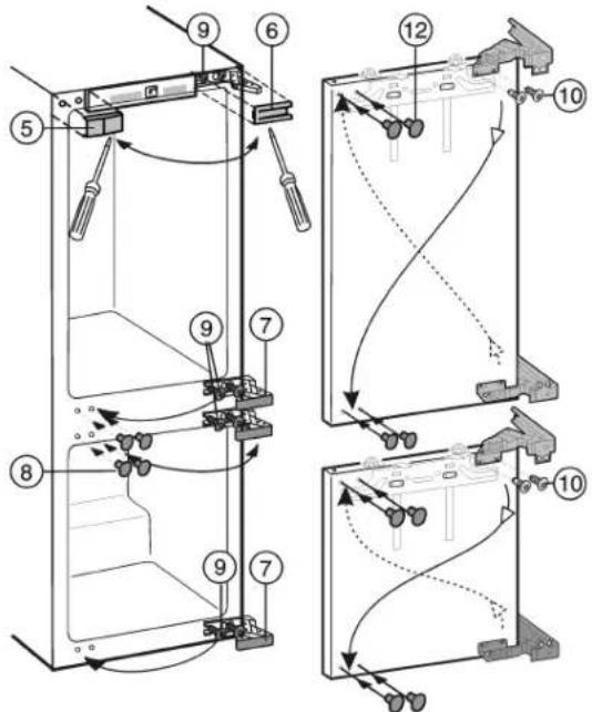
4.3.1 To change the hinges
text_image
Technical diagram showing exploded view and assembly of a device with numbered components and directional arrows indicating motion or movement.▶ Lift off the covers Fig. 3 (5,6,7,8) forwards using a flat-blade screwdriver.
▶ Loosen the top and bottom screws Fig. 3 (9) on the appliance body, without removing them.
▶ Pull the doors outwards and detach them.
▶ Transfer the screws Fig. 3 (9) to the opposite side and screw them in a little.
▶ Undo the screws Fig. 3 (10) and change over the hinges diagonally.
The screws Fig. 3 (10) are self-tapping: use a cordless screw-driver.
▶ Screw the hinges firmly into place with 4 Nm.
▶ Place plugs Fig. 3 (12) in the now unused fastening holes.
▶ Attach the doors to the pre-fitted screws Fig. 3 (9) and tighten the screws firmly with 4 Nm.

WARNING
Risk of injury due to the door dropping out! If the fastening parts are not screwed into place firmly enough, the door may drop out. This may lead to severe injuries. What is more, the door may not close and therefore the appliance may fail to cool properly.
▶ Screw the hinges firmly into place (with 4 Nm).
▶ Check all of the screws and retighten if necessary.
Make sure the following tools are on hand:
□ Cordless screwdriver Torx®15, 20, 25
□ Screwdriver
☐ Spanner 13, Spirit level
The intermediate base and side wall of the kitchen unit have to be at right angles to one another. Align the kitchen unit using a spirit level and angle. If necessary, use shims.
The appliance can also be installed in an ordinary kitchen cabinet. In this case detach the fittings of the unit door and recess. They are no longer needed as the unit door is fitted to the appliance door.
Note
▶ Before assembling the door of the unit, make sure that the admissible weight of the unit door is not exceeded.
▶ Otherwise damage to the hinges and resultant malfunction cannot be ruled out.
| Max. weight of unit door | |
| Refrigerator compartment door 14 kg | |
| Freezer compartment door 12 kg |
Check installation dimensions:
| A B C | ||
| 1772 mm - 1778 mm 17 | 69.5 mm 695 | mm |
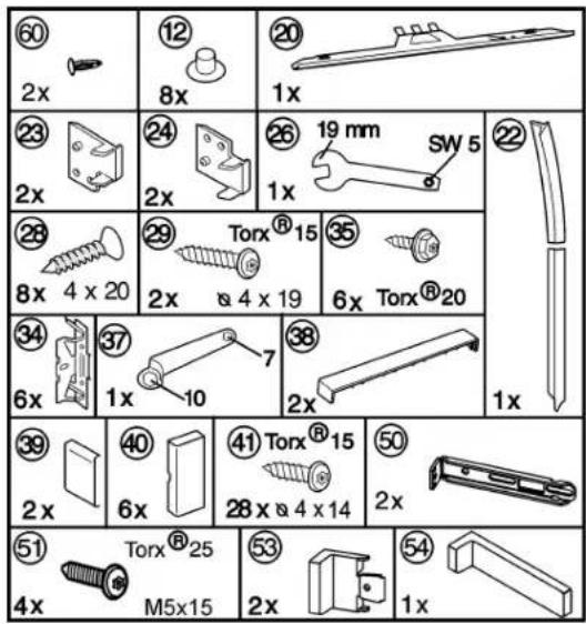
4.4 Installation
All the mounting components accompany the appliance.
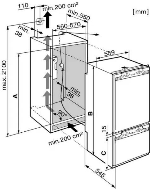
text_image
110 min.200 cm² min.550 min. 38 560-570 max. 2100 A min. 38 90° 559 min. 200 cm² B 15 C 545 [mm]Fig. 5
4.4.1 Installing the appliance
text_image
Architectural floor plan with numbered rooms and furniture placement, likely for architectural or engineering design.Fig. 6
▶ Detach the connecting cable from the rear of the appliance. Remove the cable holder otherwise there will be vibratory noise.
▶ Lay the connecting cable with the help of string in such a way that the appliance can be easily connected following installation.
▶ Slide the appliance 3/4 of the way into the recess.
▶ Remove the covers Fig. 6 (5,6,7).

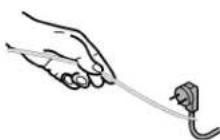
Fig. 7
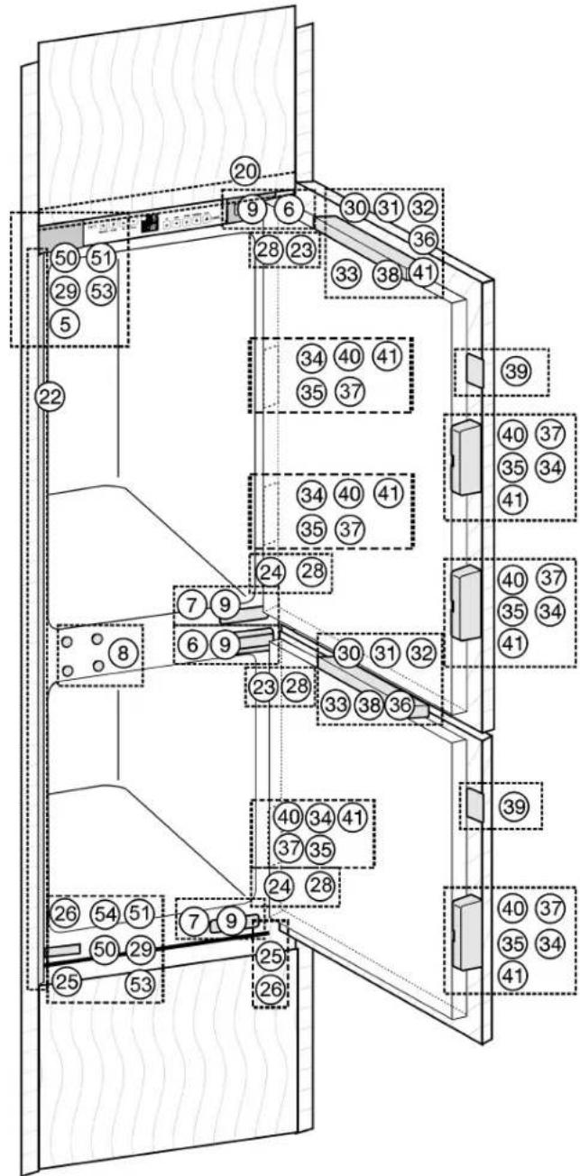
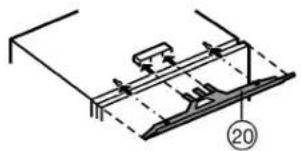
▶ Fit the equaliser trim Fig. 8 (20) concentrically onto the appliance: Slide it into the recess and engage it in the keyholes.
natural_image
Technical line drawing of a mechanical assembly with no visible text or symbolsFig. 8
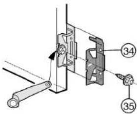
▶ Screw all the mounting brackets Fig. 9 (34) to the pre-drilled holes in the appliance door using hexagon screws Fig. 9 (35).
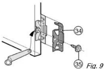
text_image
34 35 Fig. 9For 16 mm-thick unit walls = 568 mm-wide recess:
▶ Clip spacer Fig. 10 (23) onto the upper hinge and spacer Fig. 6 (24) onto the lower hinge.
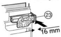
Fig. 10
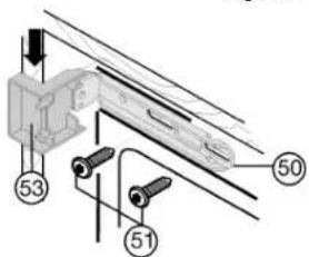
▶ Attach the top cover Fig. 11 (53) and bottom cover Fig. 11 (50) to the mounting brackets.
▶ Fasten the mounting brackets Fig. 11 (50) at the top and bottom with screws Fig. 11 (51) so that the brackets can still be moved a little to the left and right.

text_image
53 51 50Fig. 11
▶ Strip the protective film off the cover trim Fig. 12 (22). Apply the cover trim Fig. 12 (22) to the projection of the cover Fig. 11 (53) on the handle side, flush with the front, and adhesively affix it to the side wall of the appliance.
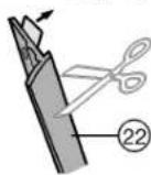
Fig. 12
▶ If necessary, shorten the cover strip Fig. 12 (22) at the bottom: The cover strip Fig. 12 (22) has to end 3 mm above the upper edge of the lower mounting bracket Fig. 6 (50).
Slide in and align the appliance:
▶ Slide in the appliance until the covers Fig. 11 (53) abut Fig. 11 against the side wall of the kitchen unit.
▶ Extend the adjustable foot. For 16 mm-thick unit walls = 568 mm-wide recess:
▶ Allow the spacers to abut against the side wall of the kitchen unit.
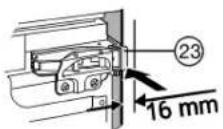
Fig. 13
For 19 mm-thick unit walls = 562 mm-wide recess:
▶ Align the front edges of the hinges so as to be flush with the side wall of the kitchen unit.
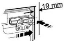
Fig. 14
For kitchen units (16 mm and 19 mm) with door stop components (knobs, sealing lips etc.):
▶ Allow for the extra distance (depth of the door stop components): Allow hinges and covers Fig. 11 (53) to protrude by the extra distance.
▶ Vertically align the appliance by means of the adjustable-height feet Fig. 6 (25), using the accompanying open-ended spanner Fig. 6 (26).
The appliance is now correctly positioned in depth. The distance from the front edge of the side wall of the unit to the appliance body is 42 mmall the way round. (Allow for door stop components, such as knobs and sealing lips.)
Note
Incorrect installation will lead to malfunction! If the distance is not kept, the door may not close. This may lead to icing, to condensate forming and to malfunction.
▶ Be sure to keep to the clearance of 42 mm all the way round. (Allow for door stop components, such as knobs and sealing lips.)
Tightly screw the appliance into place in the recess:
▶ At the top and bottom of both doors with Spax screws Fig. 15 (28) passed through the hinge plates.
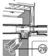
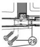
Fig. 15
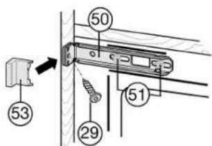
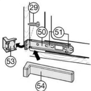
On the handle side at the top:
▶ Loosen the screws
Fig. 16 (51) a little.
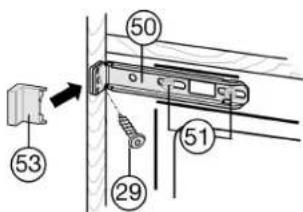
▶ Tightly screw the top mounting bracket Fig. 16 (50) to the unit wall using Spax screw Fig. 16 (29)ø4x19.
▶ Break off the projecting end of the cover Fig. 16 (53).
▶ Tighten the screws Fig. 16 (51).
▶ Put on the cover Fig. 16 (53).
On the handle side at the bottom:
▶ Loosen the screws
Fig. 17 (51) a little.
▶ Tightly screw the bottom mounting bracket Fig. 17 (50) to the unit wall using Spax screw Fig. 17 (29) ø4x19.
▶ Break off the projecting end of the cover Fig. 17 (53). It is no longer required.
▶ Tighten the screws
Fig. 17 (51).
▶ Put the cover Fig. 17 (54) on the bottom mounting bracket Fig. 17 (50).
▶ Close the appliance door.
4.4.2 Fitting the unit doors
text_image
53 50 29 51Fig. 16
text_image
Technical diagram showing labeled components of a mechanical assembly with numbered partsFig. 17

text_image
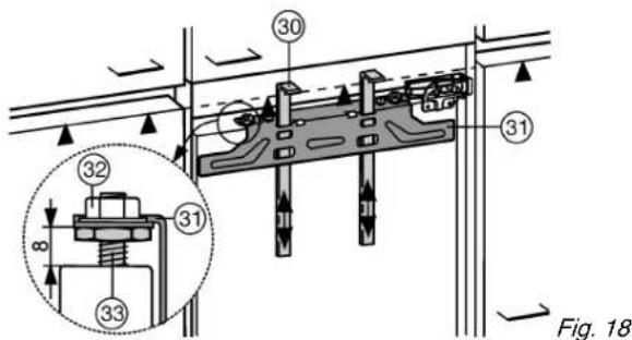
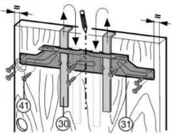
30 31 32 31 8 33 Fig. 18The fitting aids Fig. 18 (30) are required for both doors. Therefore fit the unit doors one after the other.
▶ Check 8 mm-presetting. (Distance between appliance door and lower edge of crosspiece)
Putting into operation
▶ Slide up the assembly aids Fig. 18 (30) to the height of the unit door. Lower stop edge ▲ of the assembly aid = upper edge of the unit door to be fitted.
▶ Unscrew the cross-piece Fig. 19 (31) by undoing the locknuts Fig. 19 (32).
▶ Attach the cross-piece Fig. 19 (31) together with the assembly aids Fig. 19 (30) to the inside of the unit door.
text_image
Technical diagram showing mechanical assembly with numbered components and directional arrows indicating motion or forceFig. 19
For 600 mm-wide recess:
▶ Concentrically align the crosspiece Fig. 19 (31): Mark a short centre line on the unit door and put the tip of the arrow on the crosspiece over it.
▷ Distances to the outer edge are equal at the left and right. For particle board doors:
▶ Tightly screw the crosspiece Fig. 19 (31) into place using at least 6 screws Fig. 19 (41).
For frame and panel doors:
▶ Tightly screw the crosspiece Fig. 19 (31) into place using 4 screws Fig. 19 (41) at the edge.
▶ Raise and remove the assembly aids Fig. 19 (30), turn them and slide them into the adjacent openings.
text_image
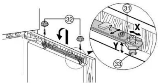
Technical diagram showing a mechanical assembly with labeled components and a magnified inset of a wooden plank structure.Fig. 20
▶ Attach the unit door to the adjusting bolts Fig. 20 (33) and loosely screw the locknuts Fig. 20 (32) onto the adjusting bolts.
▶ Close the door.
▶ Check the gap between the door and the surrounding unit doors.
▶ To laterally align the unit door: Move the unit door in the X direction.
▶ Align unit door in height and lateral inclination: Adjust the adjusting bolts Fig. 20 (33) using a screwdriver.
The unit door is flush and in alignment with the surrounding unit fronts.
▶ Tighten the lock nuts Fig. 20 (32).
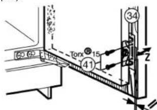
Ensure that both metal edges are flush (symbol //):
▶ Drill pilot holes in the door of the unit (possibly make preliminary hole with a bradawl).
text_image
Torx 15 41 34 2 ZFig. 21
▶ Screw the appliance door to the unit door with screws Fig. 21 (41) passed through the mounting brackets Fig. 21 (34).
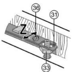
text_image
Technical diagram showing a mechanical assembly with numbered components and a zigzag arrow indicating motion or force.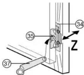
text_image
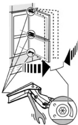
Technical diagram showing labeled mechanical components with numbered parts and directional arrowsFig. 22
▶ To align the unit door in depth Z: Undo top screws Fig. 22 (36), bottom hexagon head screws Fig. 22 (35) with ring spanner Fig. 22 (37) provided, then shift the door.
▶ Do not allow the knobs and sealing lips to abut - vital for proper function!
▶ Allow an air gap of 2 mm between the unit door and the body of the unit.
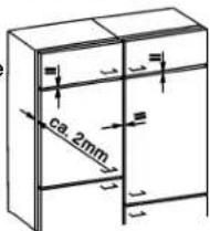
text_image
ca. 2mmFor large unit doors:
▶ fit a 3rd pair of mounting brackets
Fig. 9 (34).
▶ Use the holes pre-drilled in the handle area of the appliance door for this purpose.
▶ Check the fit of the door and adjust if necessary.
▶ Tighten all screws.
text_image
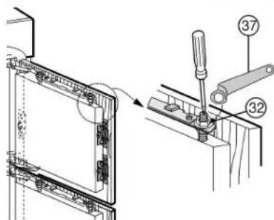
Technical diagram showing a mechanical assembly with labeled parts, including numbered callouts 32 and 37.Fig. 23
▶ Tighten the locknuts Fig. 23 (32) using the ring spanner Fig. 23 (37), while holding fast the adjusting bolts Fig. 23 (33) with a screwdriver.
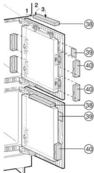
▶ Put on and engage the upper covers
Fig. 24 (38).
▶ Place lateral covers
Fig. 24 (39) in position,
slide them to the limit,
then press, until you
hear them snap into
place.
▶ Attach covers Fig. 24 (40) sideways and then draw them forwards with a screw-driver so that they snap into place.
text_image
1 2 3 38 39 40 40 38 39 40Fig. 24
▶ Put on and engage the covers Fig. 6 (5,6,7).
The door stop cushioning can be adjusted if necessary using the accompanying Allen key:
▶ For stronger spring force: turn clockwise.
▶ For lesser spring force (as-delivered): turn anticlockwise.
▶ Attach the remaining covers to the hinges.
text_image
Technical diagram showing a mechanical assembly with labeled components and an inset view of a switch mechanism.Check the following points to ensure the appliance is fitted properly. Failure to do so may lead to icing, condensate forming and malfunction:
The door has to close properly
The unit door must not butt against the unit body
The seal must have a firm fit at the upper corner on the handle side. To check, darken the room, place a torch inside the appliance at the top and close the door. If light shines through, check the assembly.
4.5 Disposing of packaging

WARNING
Danger of suffocation due to packing material and plastic film!
▶ Do not allow children to play with packing material.
The packaging is made of recyclable materials:
- corrugated board/cardboard
- expanded polystyrene parts
- polythene bags and sheets
- polypropylene straps
- nailed wooden frame with polyethylene panel*
▶ Take the packaging material to an official collecting point.
4.6 Connecting the appliance
NOTICE
Risk of damage to the electronic control system!
▶ Do not use stand-alone inverters (conversion of d.c. to a.c./three-phase) or energy saving plugs.

WARNING
Fire and overheating hazard!
▶ Do not use extension cables or multiple socket outlets.
The type of current (alternating current) and voltage at the installation site have to conform with the data on the type plate (see Appliance at a glance).
Connect the appliance only with a properly installed socket outlet with earthing contact. The socket outlet must be fused with 10 A or higher.
It must be easily accessible so that the appliance can be quickly disconnected from the supply in an emergency. It must be outside the area of the rear of the appliance.
▶ Check the electrical connection.
▶ Plug in the power plug.


4.7 Switching on the appliance
Note
▶ To switch on the entire appliance it is necessary only to switch on the freezer compartment.
Put the appliance into operation about 2 hours before first loading food to be frozen.
Do not load food to be frozen before the temperature display reads -18 °C.
4.7.1 Switching on the freezer compartment
▶ Press On/Off button, freezer compartment Fig. 2 (3).
The refrigerator compartment temperature display shows the set temperature.
The temperature display of the freezer compartment flashes until the temperature is sufficiently low. If the temperature is above 0 °C, dashes flash. If it is below, the set temperature flashes.
4.7.2 Switching on the refrigerator compartment
▶ Press On/Off button, refrigerator compartment Fig. 2 (11).
The interior light is on when the door is open.
The temperature display shines. The refrigerator compartment is switched on.
5 Control
5.1 Brightness of the temperature display
You can adjust the brightness of the temperature display to the light conditions of the room in which the appliance is installed.
5.1.1 Adjusting the brightness
The brightness can be adjusted between h1 (minimum luminance) and h5 (maximum luminance).
▶ To activate the setting mode: Press the Fast Freeze button Fig. 2 (2) for about 5 seconds.
The Fast Freeze button flashes. The display indicates c.
▶ Using the "+" setting button, freezer compartment Fig. 2 (5) and "-" setting button, freezer compartment Fig. 2 (4), select h.
▶ To confirm: Briefly press the Fast Freeze button Fig. 2 (2).
▶ To make the display brighter: Press the "+" setting button, freezer compartment Fig. 2 (5).
▶ To make the display darker: Press the "-" setting button, freezer compartment Fig. 2 (4).
▶ To confirm: Press the Fast Freeze button Fig. 2 (2).
The brightness is adjusted to the new value.
▶ To deactivate the setting mode: Press the On/Off button, freezer compartment Fig. 2 (3).
-or-
▶ Wait for 5 minutes.
The temperature is indicated again in the temperature display.
5.2 Child proofing
The child-proofing function enables you to make sure that the appliance is not inadvertently switched off by playing children.
5.2.1 Setting the child lock
▶ To activate the setting mode: Press the Fast Freeze button Fig. 2 (2) for about 5 seconds.
▷ The Fast Freeze button flashes. The display indicates c.
▶ To confirm, briefly press the Fast Freeze button Fig. 2 (2).
▶ To switch on: Using the "+" setting button, freezer compartment Fig. 2 (5) or "-" setting button, freezer compartment Fig. 2 (4), select c1.
▶ To switch off: Using the "+" setting button, freezer compartment Fig. 2 (5) or "-" setting button, freezer compartment Fig. 2 (4), selectc0.
▶ To confirm: Press the Fast Freeze button Fig. 2 (2).
▷ When the child lock symbol Fig. 2 (8) shines, the child lock is activated.
▶ To deactivate the setting mode: Press On/Off button, freezer compartment Fig. 2 (3).
-or-
▶ Wait for 5 minutes.
▷ The temperature is indicated again in the temperature display.
5.3 Door alarm
For refrigerator and freezer compartment
If the door is open longer then 60 s, the audible alarm sounds.
The audible alarm is automatically silenced when the door is closed.
5.3.1 Muting the door alarm
The audible alarm can be muted when the door is open. The sound switch-off function is active as long as the door is left open.
▶ Press alarm button Fig. 2 (1).
▷ The door alarm is silenced.
5.4 Temperature alarm
The audible alarm sounds if the freezer temperature is not cold enough.
The temperature display flashes at the same time.
The cause of the temperature being too high may be:
- warm fresh food was placed inside
- too much warm ambient air flowed in when rearranging and removing food
- power failure for some time
- the appliance is faulty
The audible alarm is automatically silenced and the temperature display stops flashing when the temperature is sufficiently cold again.
If the alarm status persists: (see Malfunction).
Note
Food may be spoilt if the temperature is not cold enough.
▶ Check the quality of the food. Do not consume spoiled food.
5.4.1 Muting the temperature alarm
The audible alarm can be muted. When the temperature is sufficiently cold again, the alarm function is active again.
▶ Press alarm button Fig. 2 (1)
▷ The audible alarm is silenced.
5.5 Refrigerator compartment
The natural circulation of air in the refrigerator compartment results in zones differing in temperature. It is coldest directly above the vegetable drawers and at the rear wall. It is warmest at the top front of the compartment and in the door.
5.5.1 Food refrigeration
Note
The energy consumption increases and the cooling performance decreases if the ventilation is inadequate.
▶ Always keep the air slits of the fan free.
▶ Store perishable food such as ready-to-serve dishes, meat products and sausages in the coldest zone. Place butter and preserves in the upper area and in the door (see Appliance at a glance).
▶ Use recyclable plastic, metal, aluminium and glass containers and cling film for wrapping.
▶ Use the front area of the refrigerator compartment floor only for briefly putting down cooled products, e.g. when rearranging and sorting. However do not leave cooled products there otherwise they may be pushed back or tipped over when the door is closed.
▶ Do not store food too close together to enable good air circulation.
▶ To safeguard bottles from tipping over: move the bottle holder.
5.5.2 Setting the temperature
The temperature can be set from 11 °C to 2 °C, the recommended temperature is 5 °C.
For a higher temperature setting: press "+" +" button, refrigerator compartment Fig. 2 (10).
For a lower temperature setting: press "-" button, refrigerator compartment Fig. 2 (9).
The first time the button is pressed, the value set so far is indicated in the refrigerator compartment temperature display.
▶ To change the temperature in 1 °C steps: briefly press the button.
▶ To change the temperature continuously: hold down the button.
The value is displayed flashing during the setting operation.
The actual temperature is displayed about 5 s after the last press of a button. The temperature slowly adjusts to the new value.
5.5.3 Fast Cool
Use Fast Cool to activate the highest cooling performance to reach lower cooling temperatures. Fast Cool is used for rapidly cooling large amounts of food.
Fast Cool has a slightly higher energy consumption
To cool using Fast Cool
▶ Briefly press the Fast Cool button Fig. 2 (12).
▷ The Fast Cool button Fig. 2 (12)shines.
The cooling temperature drops to the coldest value. Fast Cool is switched on.
▷ Fast Cool switches off automatically after approx. 6 hours. The appliance continues to operate in the energy-saving, normal mode.
To switch off Fast Cool ahead of time
▶ Briefly press the Fast Cool button Fig. 2 (12).
The Fast Cool button Fig. 2 (12) goes out.
▷ Fast Cool is switched off.
5.5.4 Fan
With the fan you can rapidly cool large quantities of fresh food or achieve a relatively even distribution of temperature across all the storage levels.
The forced-air cooling is to be recommended:
- at high room temperature (from approx. 30 °C)
- at high humidity
The forced-air cooling uses slightly more energy. To save energy, the fan switches off automatically when the door is open.
▶ Briefly press the Fan button Fig. 2 (13).
The Fan button shines, the fan is switched on.
▶ Briefly press the Fan button Fig. 2 (13).
The Fan button goes out, the fan is switched off.
5.5.5 Relocating the shelves
The shelves have stops preventing them from being unintentionally pulled out.
▶ Lift the shelf and draw it out forwards.
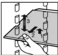
text_image
Diagram showing a hand holding test tubes with numbered arrows indicating measurement or force direction, likely illustrating a test setup or measurement process.▶ Insert shelf with the raised edge pointing upwards at the back.
The food does not freeze onto the rear wall.
5.5.6 Using the sectioned shelf
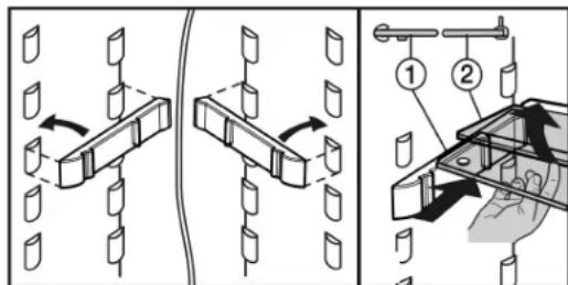
text_image
Technical diagram illustrating mechanical assembly steps with labeled components and directional arrowsFig. 25
The glass shelf with stop face (2) has to be at the back.
5.5.7 Moving the storage rack
▶ Remove storage rack according to illustration.
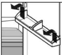
Always remove the butter and cheese compartment together with the lid.
▶ To remove lid: Press one side part of the butter and cheese compartment outwards until the lid pin is clear and then remove the lid sideways.
5.5.8 Removing the bottle holder
▶ Remove the bottle holder according to the illustration.
5.6 Freezer compartment
You can store frozen food, make ice cubes and freeze fresh food in the freezer compartment.
5.6.1 Freezing food
The rating plate indicates the maximum quantity of fresh food you can freeze within 24 hours (see Appliance at a glance) under "Freezing capacity ... kg/24h".
The maximum load of frozen food for the drawers is 25 kg each and for the shelves 35 kg each.
A vacuum is generated after the door is closed. After closing the door, wait for about 1 minute and then it opens more easily.

CAUTION
Risk of injury due to broken glass!
Bottles and cans containing drinks may burst when being frozen. This applies particularly to sparkling drinks.
▶ Do not freeze bottles and cans containing drinks!
In order that the food is rapidly frozen through to the core, do not exceed the following quantities per pack:
- Fruit, vegetables up to 1 kg
- Meat up to 2.5 kg
Pack the food in portions in freezer bags, reusable plastic, metal or aluminium containers.
5.6.2 Thawing food
- in the refrigerator compartment
- at room temperature
- in a microwave oven
- in a conventional or fan oven
▶ Food once thawed should be re-frozen only in exceptional cases.
5.6.3 Setting the temperature in the freezer compartment
The appliance is pre-set for normal operation.
The temperature can be set between -16 °C and -26 °C, the recommended temperature is -18 °C.
▶ To set the temperature higher: press setting button “+” freezer compartment Fig. 2 (5).
▶ To set the temperature lower: press setting button “-” freezer compartment Fig. 2 (4).
When the button is pressed the first time, the previous value is indicated in the temperature display of the freezer compartment.
▶ To change the temperature in 1 °C steps: briefly press the button.
-or-
▶ To change the temperature continuously: hold down the button.
The value is displayed flashing during the setting operation.
The actual temperature is displayed about 5 s after the last press of a button. The temperature slowly adjusts to the new value.
5.6.4 Fast-Freeze
With this function you can freeze fresh food quickly through to the core. The appliance operates with maximum refrigeration. The noise of the refrigeration unit may be temporarily louder as a result.
The maximum amount of fresh food which can be frozen in 24 h is indicated on the type plate under "freezing capacity ... kg/24h". This amount varies according to the model and climate rating.
You have to activate FastFreeze in good time, depending on how much fresh food is to be frozen: about 6 hours before placing the food inside in case of small amounts and about 24 hours in advance in case of the maximum amount of food to be frozen.
You do not have to activate Fast-Freeze in the following cases:
- when placing frozen food in the freezer
- when freezing up to approx. 2 kg fresh food daily
Freezing with Fast-Freeze
▶ Briefly press the Fast-Freeze button Fig. 2 (2) once.
The Fast-Freeze button Fig. 2 (2) shines.
The freezer temperature drops, the appliance operates with maximum refrigerating performance.
For a small amount of food:
▶ wait about 6 h.
▶ Place the fresh food in the top drawers. For the maximum amount of food:
▶ wait about 24 h.
▶ Place wrapped food straight on the shelves and, once frozen, put it into the drawers.
Fast-Freeze is automatically deactivated. Depending on the quantity placed inside, after 30 h at the earliest, 65 h at the latest.
▷ Freezing is concluded.
▷ The Fast-Freeze button Fig. 2 (2) is dark.
The appliance continues to operate in the energy-saving, normal mode.
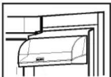
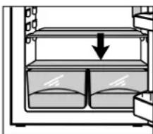
5.6.5 Drawers
Note
The energy consumption increases and the cooling performance decreases if there is insufficient ventilation.
For appliances with NoFrost:
Leave the bottom drawer in the appliance!
▶ Always keep the air slits of the fan free at the rear wall!
natural_image
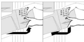
Illustration of hands using a book and pen, no text or symbols visible▶ To store frozen food directly on the shelves: pull the drawer forwards and lift it out.
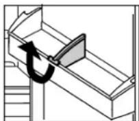
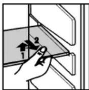
5.6.6 Shelves
▶ To remove the shelf: lift up at the front and pull out.
▶ To put the shelf back: simply push in as far as it will go.
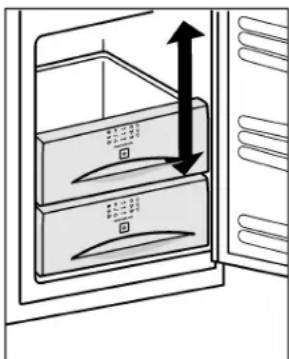
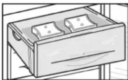
5.6.7 VarioSpace
Apart from being able to remove the drawers, you can also remove the shelves, creating space for large items of frozen food. Poultry, meat, large pieces of game and high bakery products can be frozen in one piece and prepared.
The maximum load of frozen food for the drawers is 25 kg each and for the shelves 35 kg each.
natural_image
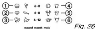
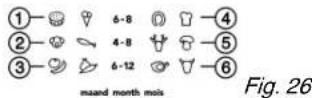
Diagram of a refrigerator interior showing airflow direction with arrows (no text or symbols)5.6.8 Information system
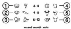
Fig. 26
(1) Ready-made meals, ice cream (4) Sausages, bread
(2) Pork, fish (5) Game, mushrooms
(3) Fruit, vegetables (6) Poultry, beef/veal
The figures indicate the storage time in months for several types of frozen food in each case. Storage times given are guide times.
5.6.9 Cold storage accumulators
The cold storage accumulators prevent the temperature from rising too fast in the event of power failure.
Using cold storage accumulators
▶ Place the cold storage accumulators in the top freezer compartment to save space.
▶ Place the frozen cold storage accumulators on the frozen food in the upper front area of the freezer compartment.
natural_image
Line drawing of a drawer with two compartments, no text or symbols present6 Maintenance
6.1 Defrosting with NoFrost
The NoFrost system automatically defrosts the appliance.
Refrigerator compartment:
The defrost water evaporates due to the compressor heat. Drops of water on the rear wall are perfectly normal.
▶ Regularly clean the drain opening to allow the water to flow away (see 6.2).
Freezer compartment:
The moisture condenses on the evaporator, is periodically defrosted and evaporates.
▶ The appliance does not have to be manually defrosted.
6.2 Cleaning the appliance
Before cleaning:

CAUTION
Risk of injury and damage as a result of hot steam!
Hot steam may damage the surfaces and cause burns.
▶ Do not use any steam cleaners!
NOTICE
Incorrect cleaning damages the appliance!
▶ Do not use cleaning agents in concentrated form.
▶ Do not use any scouring or abrasive sponges or steel wool.
▶ Do not use any cleaning agents containing sand, chloride, chemicals or acid.
▶ Do not use chemical solvents.
▶ Do not damage or remove the type plate on the inside of the appliance. It is important for the customer service.
▶ Do not pull off, bend or damage cables or other components.
▶ Do not allow any cleaning water to enter the drain channel, ventilation grille or electrical parts.
▶ Empty the appliance.
▶ Pull out the plug.

- Use soft cleaning cloths and a multi-purpose cleaning agent with neutral pH value.
- Only use food compatible cleaning and care agents on the inside of the appliance.
Interior:
Cleaning inner and outer plastic surfaces:
▶ Clean surfaces by hand with lukewarm water and a little washing-up liquid.
▶ To clean the drain opening: remove any deposits with a fine instrument, e.g. a cotton bud.
natural_image
Diagram of a storage or lifting mechanism with a downward arrow indicating compression (no text or symbols present)Items of equipment:
▶ Clean items of equipment by hand with lukewarm water and a little washing-up liquid.
▶ For cleaning, remove the support rails for the half-sized glass shelves.
After cleaning:
▶ Wipe dry the appliance and items of equipment.
▶ Connect the appliance and switch it on again.
▶ Switch on Fast-Freeze (see 5.6.4)
When the temperature is sufficiently cold:
▶ Put the food back inside.
6.3 Customer service
First check whether you can correct the fault yourself by reference to the list (see Malfunction). If this is not the case, please contact the customer service whose address is given in the enclosed customer service list.

WARNING
Risk of injury if repair work is not carried out professionally!
▶ Have any repairs and action - not expressly specified - on the appliance and mains cable carried out by service personnel only. (see Maintenance)
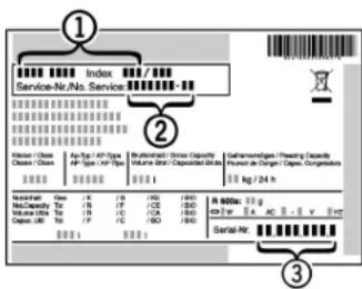
▶ Read the appliance designation
Fig. 27 (1), service No. Fig. 27 (2) and serial No. Fig. 27 (3) off the type plate located inside the appliance on the left-hand side.
text_image
Index Service-Nr./No. Service ① ② Hörsen / Chies Chies / Chies Apt./Top / APT-Type APT-Type / APT-Type Basilikanin / Dience Capacité Volume diter / Desapacité (Gains) Volume diter / Desapacité (Gains) Gehannemögen/ Prenning Capacité Presen de Départe / Capacé Gesamtions kg / 24 m Machanlar Class T1 T2 T3 T4 T5 T6 T7 T8 T9 T10 T11 T12 T13 T14 T15 T16 T17 T18 T19 T20 T21 T22 T23 T24 T25 T26 T27 T28 T29 T30 T31 T32 T33 T34 T35 T36 T37 T38 T39 T40 T41 T42 T43 T44 T45 T46 T47 T48 T49 T50 T51 T52 T53 T54 T55 T56 T57 T58 T59 T60 T61 T62 T63 T64 T65 T66 T67 T68 T69 T70 T71 T72 T73 T74 T75 T76 T77 T78 T79 T80 T81 T82 T83 T84 T85 T86 T87 T88 T89 T90 T91 T92 T93 T94 T95 T96 T97 T98 T99 T100Fig. 27
▶ Notify the customer service, specifying the fault, appliance designation Fig. 27 (1), service No. Fig. 27 (2) and serial No. Fig. 27 (3).
▷ This will help us to provide you with a faster and more accurate service.
▶ Keep the appliance closed until the customer service arrives.
▷ The food will stay cool longer.
▶ Pull out the mains plug (not by pulling the connecting cable) or switch off the fuse.
7 Malfunction
Your appliance is designed and manufactured for a long life span and reliable operation. If a malfunction nonetheless occurs during operation, check whether it is due to a handling error. In this case you will have to be charged for the costs incurred, even during the warranty period. You may be able to rectify the following faults yourself:
Appliance does not work.
→ The appliance is not switched on.
▶ Switch on the appliance.
→ The power plug is not properly inserted in the wall socket.
▶ Check power plug.
→ The fuse of the wall socket is not in order.
▶ Check fuse.
The compressor runs for a long time.
→ The compressor switches to a low speed when little cold is needed. Although the running time is increased as a result, energy is saved.
▶ This is normal in energy-saving models.
→ Fast-Freeze is activated.
▶ The compressor runs for longer in order to rapidly cool the food. This is normal.
→ Fast-Cool is activated.
The compressor runs for longer in order to rapidly cool the food. This is normal.
The inverter regularly flashes every 15 seconds\*.
→ The inverter is equipped with a diagnostic LED.
▶ The flashing is normal.
Excessive noise.
→ Speed-controlled* compressors may produce varying running noise due to different speed steps.
▶ The sound is normal.
A bubbling and gurgling noise.
→ This noise comes from the refrigerant flowing in the refrigeration circuit.
▶ The sound is normal.
A quiet clicking noise.
→ The noise is produced whenever the refrigeration unit (motor) automatically switches on or off.
▶ The sound is normal.
A hum. It is briefly a little louder when the refrigeration unit (the motor) switches on.
→ The refrigeration increases automatically when Fast-Freeze is activated, fresh food has just been placed in the appliance or the door has been left open for a while.
▶ The sound is normal.
→ The refrigeration increases automatically when the Fast-Cool function is activated, fresh food has just been placed in the appliance or the door has been left open for a while.
▶ The sound is normal.
→ The ambient temperature is too high.
▶ Solution: (see 1.2)
A low hum.
→ The sound is produced by air flow noise of the fan.
▶ The sound is normal.
Vibratory noise.
→ The appliance is not standing firmly on the floor. As a result, adjoining units or objects are set into vibration by the running refrigeration unit.
▶ Move bottles and containers apart.
The temperature display indicates: F0 to F5.
→ There is a fault.
▶ Contact the customer service (see Maintenance).
The temperature display indicates: nA
→ The freezer temperature rose too high over the last hours or days due to a power failure or power interruption. When the power interruption is over, the appliance will continue to operate in the last temperature setting.
▶ Press alarm button Fig. 2 (1)
The warmest temperature reached during the power failure will appear in the temperature display for about 60 s. After that, the actual temperature in the freezer will re-appear.
▶ To prematurely cancel the display of the warmest temperature: press alarm button Fig. 2 (1).
▶ Check the quality of the food. Do not consume spoiled food. Do not re-freeze thawed food.
The temperature is not cold enough.
→ The door of the appliance is not properly closed.
▶ Close the door of the appliance.
→ Insufficient ventilation.
▶ Clear ventilation grilles.
→ The ambient temperature is too high.
▶ Solution: (see 1.2).
→ The appliance was opened too frequently or for too long.
▶ Wait until the appliance reaches the required temperature itself. If not, contact the customer service. (see Maintenance).
→ Too much fresh food was placed inside without Fast-Freeze.
▶ Solution: (see 5.6.4)
→ The temperature is incorrectly set.
▶ Set to a colder temperature and check after 24 h.
→ The appliance is too close to a heat source.
▶ Solution: (see Putting into operation).
→ The appliance was not inserted properly into the recess.
▶ Check whether the appliance was inserted correctly and the door closes properly.
The interior light is not on.
→ The appliance is not switched on.
▶ Switch on the appliance.
→ The door was open longer than 15 min.
The interior light automatically switches off if the door has been open for about 15 min.
→ The LED lighting is defective or the cover is damaged:

WARNING
Risk of injury due to electric shock!
Live parts are located under the cover.
▶ Have the LED interior light changed or repaired only by the customer service or by specialized personnel trained for the purpose.

WARNING
Danger of injury due to laser radiation, class 1M.
▶ Do not look inside when the cover is open.
8 Decommissioning
8.1 Switching off the appliance
Note
▶ To switch off the entire appliance it is necessary only to switch off the freezer compartment.
8.1.1 Switching off the freezer compartment
▶ Press On/Off button, freezer compartment Fig. 2 (3) for about 2 s.
The temperature displays are dark. The appliance is switched off.
8.1.2 Switching off the refrigerator compartment
Note
▶ The refrigerator compartment can be switched off separately, if required.
▶ Press On/Off button, refrigerator compartment Fig. 2 (11) for about 2 s.
The temperature display of the refrigerator compartment Fig. 2 (7) is dark. The refrigerator compartment is switched off.
8.2 Taking the appliance out of service
▶ Empty the appliance.
▶ Pull out the power plug.
▶ Clean the appliance (see 6.2).
▶ Leave the door open to prevent odour.

9 Disposing of the appliance
The appliance contains some reusable materials and should be disposed of properly - not simply with unsorted household refuse. Appliances which are no longer needed must be disposed of in a professional and appropriate way, in accordance with the current local regulations and laws.
When disposing of the appliance, ensure that the refrigeration circuit is not damaged to prevent uncontrolled escape of the refrigerant it contains (data on type plate) and oil.
▶ Disable the appliance.
▶ Pull out the plug.
▶ Cut through the connecting cable.
Sommaire
text_image
Diagram of an open refrigerator with numbered compartments and food items, including a rose dish and glassware.Fig. 1
text_image
Technical diagram showing exploded view of a refrigerator with numbered components and directional arrows indicating movement or assembly.text_image
Architectural floor plan with numbered rooms and structural annotationsnatural_image
Technical line drawing of a mechanical assembly with no visible text or symbolsFig. 8
text_image
Technical diagram showing mechanical assembly with numbered parts labeled 34 and 35Fig. 9
text_image
Technical diagram showing two mechanical assembly steps with bolted components and numbered calloutsFig. 15
text_image
Technical diagram showing mechanical assembly with numbered components and directional arrows indicating motion or forceFig. 19
text_image
Technical diagram showing a mechanical assembly with labeled components and a magnified inset of a wooden structure with coordinate axes X, Y, Z.Fig. 20
text_image
Technical diagram showing a mechanical assembly with numbered components and a zigzag arrow indicating direction or force.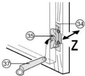
text_image
Technical diagram showing labeled mechanical components with numbered parts and directional arrowsFig. 22
text_image
Technical diagram showing assembly steps with numbered components, including a close-up of a component being inserted into a frame.Fig. 23
text_image
Technical diagram showing mechanical assembly with labeled components and a magnified inset of a component detailtext_image
Diagram showing a hand holding a tray with three labeled parts (1, 2, 3) and directional arrows indicating movement or force.text_image
Technical diagram illustrating mechanical assembly steps with labeled components and directional arrowsnatural_image
Two-panel illustration showing hands reading a document with arrows indicating motion (no text or symbols)natural_image
Diagram of a refrigerator interior showing airflow direction with arrows (no text or symbols)5.6.8 Système info