D525C - Grass trimmer Anova - Free user manual and instructions
Find the device manual for free D525C Anova in PDF.

User questions about D525C Anova
0 question about this device. Answer the ones you know or ask your own.
Ask a new question about this device
Download the instructions for your Grass trimmer in PDF format for free! Find your manual D525C - Anova and take your electronic device back in hand. On this page are published all the documents necessary for the use of your device. D525C by Anova.
USER MANUAL D525C Anova
natural_image
Black and white photo of a manual lawn brush tool with adjustable handle and head (no visible text or symbols)ES
ANOVA®
Precaución
natural_image
Three-panel black-and-white photo showing mechanical assembly steps: tool, press, and clamp (no visible text or symbols)natural_image
Mechanical component diagram showing a lever and base with motion arrow (no text or symbols)Advertencia
natural_image
Close-up of a hand holding a black cylindrical object with a D-gel (10x) label, no visible text or symbols on the object itself.natural_image
Close-up of a mechanical device with a transparent cylindrical component inserted, no visible text or symbolsnatural_image
Black handheld device with control panel and 'ON' label (no visible text or symbols on device body)natural_image
Close-up of a mechanical device with no visible text or symbolsnatural_image
Close-up of hands using a screwdriver to adjust or install a mechanical component (no visible text or symbols)natural_image
Close-up of a mechanical device with visible components and mounting features (no text or symbols)natural_image
Close-up of hands using a screwdriver to adjust or install a black mechanical component (no visible text or symbols)natural_image
Close-up of a black mechanical lever handle with a labeled 'OFF' button (no other text or symbols visible)Advertencia
natural_image
Close-up of hands holding a black mechanical device with ventilation slots (no visible text or symbols)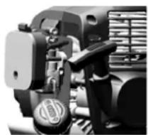
natural_image
Close-up of a mechanical assembly with no visible text or symbols
Advertencia
12. CERTIFICADO CE
natural_image
Black and white photo of a manual lawn brush tool with adjustable handle and head (no visible text or symbols)PT
ANOVA®
Cuidado
natural_image
Three-panel black-and-white photo showing mechanical assembly steps: tool, press, and clamp (no visible text or symbols)natural_image
Mechanical component diagram showing a lever and base with motion arrow (no text or symbols)Aviso
natural_image
Black handheld device with control panel and 'ON' label (no visible text or symbols on body)natural_image
Close-up of a mechanical device with visible gears and a labeled component (no text or symbols)natural_image
Close-up of a finger pressing a button labeled '10x' (no other text or symbols visible)natural_image
Close-up of hands using a screwdriver to adjust or install a mechanical component (no visible text or symbols)natural_image
Close-up of a mechanical device with visible gears and buttons, no text or symbols presentnatural_image
Close-up of hands using a screwdriver to adjust or install a black mechanical component (no visible text or symbols)natural_image
Exterior view of a black handheld device with a 'OFF' button and control panel (no text or symbols on the device itself)Aviso
natural_image
Close-up of hands adjusting a black plastic device with a handle (no visible text or symbols)
natural_image
Close-up of a mechanical assembly with no visible text or symbolsAviso
12. CERTIFICADO CE
natural_image
Black and white photo of a small manual lawn brush tool with adjustable handle and head (no visible text or symbols)FR
ANOVA®
natural_image
Four black-and-white icons representing weather, fire, person silhouette, and house (no text or symbols)Prudence
natural_image
Three-panel black-and-white photo showing mechanical assembly steps: tool, hand holding tool, and close-up of a mechanical component (no visible text or symbols)natural_image
Mechanical component diagram showing a lever and base with motion arrows (no text or symbols)Avertissement
natural_image
Close-up of a hand holding a black circular object with a D-10x 10x label (no readable text or symbols beyond branding)5.2.2. Vidange de carburant
natural_image
Close-up of a mechanical device with a white component and black components, no visible text or symbolsnatural_image
Black handheld device with control panel and 'ON' label (no visible text or symbols on body)natural_image
Close-up of a mechanical device with visible gears and housing (no text or symbols)natural_image
Close-up of hands using a screwdriver to adjust or install a mechanical component (no visible text or symbols)FR
natural_image
Close-up of a mechanical device with visible gears and buttons, no text or symbols presentnatural_image
Close-up of hands using a screwdriver to adjust or install a mechanical component (no visible text or symbols)natural_image
Close-up of a black handheld device with a 'OFF' button and control knob (no visible text or symbols on the device itself)Avertissement
natural_image
Close-up of mechanical components including a hand holding a tool and a motor assembly (no visible text or symbols)6.3. Bougie
Avertissement
12. CERTIFICAT CE
SOCIÉTÉ DE DISTRIBUTION
MILLASUR, SL
DÉCLARATION DE CONFORMITÉ CE
Directive 2006/42/CE
2014/30/UE
natural_image
Black and white photo of a manual lawn brush tool with adjustable handle and head (no visible text or symbols)IT
ANOVA®

Attenzione
natural_image
Three-panel black-and-white photo showing a mechanical assembly: front view, hand tool, and close-up of a mechanical component (no visible text or symbols)natural_image
Mechanical component diagram showing a lever and base with motion arrows (no text or symbols)Avvertimento
natural_image
Close-up of a hand holding a black cylindrical object with a D-gel (10x) label, no visible text or symbols on the object itself.5.2.2. Scarico del carburante
natural_image
Close-up of a robotic arm interacting with a white mechanical component (no visible text or symbols)natural_image
Black handheld device with a control panel and 'ON' label, no visible text or symbols on the device itself.natural_image
Close-up of a mechanical device with visible gears and a labeled component (no text or symbols)natural_image
Close-up of a finger pressing a button labeled '10x' with a small icon, no readable text or symbols beyond the label.natural_image
Close-up of hands using a tool to adjust or install a mechanical component (no visible text or symbols)natural_image
Close-up of a mechanical device with visible components and mounting brackets (no text or symbols)natural_image
Close-up of hands using a power tool to adjust or install a black electric motor (no visible text or symbols)natural_image
Exterior view of a black handheld device with a labeled 'OFF' button (no other text or symbols visible)Avvertimento
natural_image
Close-up of a hand operating a mechanical device with a close-up view of its internal components (no visible text or symbols)6.3. Candela
Avvertimento
Instructions and user manual

natural_image
Black and white photo of a manual lawn brush tool with adjustable handle and head (no visible text or symbols)EN
ANOVA®
Anova We would like to congratulate you on choosing one of our products and guarantee the assistance and cooperation that has always distinguished our brand over time.
This machine is designed to last for many years and to be of great use if used according to the instructions in the user manual. We therefore recommend that you carefully read this instruction manual and follow all our recommendations.
For more information or questions, you can contact us through our web support at www.anova.es
INFORMATION ABOUT THIS MANUAL
Pay attention to the information provided in this manual and on the appliance for your safety and the safety of others.
- This manual contains instructions for use and maintenance.
- Take this manual with you when you go to work with the machine.
- The content is correct at the time of printing.
- We reserve the right to make changes at any time without affecting our legal responsibilities.
- This manual is considered an integral part of the product and must remain with it in case of loan or resale.
- Request a new manual from your distributor if it is lost or damaged.
READ THIS MANUAL CAREFULLY BEFORE USING THE MACHINE

To ensure your machine delivers the best results, carefully read the usage and safety guidelines before using it.
OTHER WARNINGS:
Improper use could cause damage to the machine or other objects.
Adapting the machine to new technical requirements could cause differences between the content of this manual and the product purchased.
Read and follow all instructions in this manual. Failure to follow these instructions could result in serious personal injury.
INDEX
- SAFETY INSTRUCTIONS
- TECHNICAL SPECIFICATIONS
- PRODUCT DESCRIPTION
- MOUNTING
- INSTRUCTIONS FOR USE
- MAINTENANCE AND CLEANING
- STORAGE
- TROUBLESHOOTING
- WARRANTY
10.ENVIRONMENT - EXPLODED VIEW
12.CE CERTIFICATE
1. SAFETY INSTRUCTIONS
1.1. Safety symbols
HeThe use of symbols in this manual is intended to draw your attention to potential hazards. Safety symbols and their accompanying explanations must be fully understood. Warnings alone do not eliminate risks and cannot replace correct actions to prevent accidents.


Read the instruction manual and follow all safety warnings and instructions before any use; see the relevant paragraph in this manual. Ignoring this warning could cause an accident, both for you and others. To limit the risk of injury, fire, or electrocution, always follow the recommendations provided.
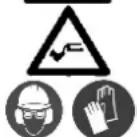
It complies with the European regulations applicable to this product.
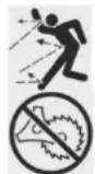
Warning: Small objects can be propelled at high speed, causing injuries. Danger of injury from projectiles. Maintain a safe distance.
It is not permitted to use the cutting head (nylon) with cutting discs, toothed saw blades, rigid or metallic blades.
Keep all children, spectators and helpers 15 meters away from the brush cutter.
The exhaust and other engine parts will get very hot during use, do not touch them.
Gasoline is highly flammable. Do not light flames or smoke near the machine.
Be careful of flying objects that may be struck by the cutting accessories. Never use the machine without the guard properly installed.
Pay close attention to your feet to avoid injury during operation.
When using the product, wear ear protection, eye protection, head protection, and protective gloves.
Wear non-slip footwear when using the device.
"Mix petrol" refueling symbol on the fuel tank cap.
Do not expose to rain.
Starting the engine creates sparks. These sparks can ignite nearby flammable gases.
Engines emit carbon monoxide, an odorless and colorless gas. Breathing carbon monoxide can cause nausea, fainting, or death.
For outdoor use only.
1.2. Safety warnings
▲ Important
The machine will always be used in accordance with the manufacturer's instructions set out in the instruction manual.
The manufacturer will not be liable in cases of improper use or modifications to the product. Furthermore, follow the safety advice, the installation and operating manual, and current accident prevention regulations. Appliances with incorrect or missing parts must not be used. The distributor can provide you with information on replacement parts.
▲ Important
Because Anova regularly improves its products, you may find slight differences between your machine and the descriptions in this manual. Anova may make changes to the machine without prior notice and without obligation to update the manual, although essential safety and operating features will remain unchanged.
Note: Due to technical product updates, this document is subject to change without notice.
1.2.1. Training
a) Read the instructions carefully. Be familiar with the controls and proper use of the equipment.
b) Never use the product for any purpose other than that for which it was designed.
c) Never allow children or people unfamiliar with these instructions to use the machine.
d) Please note that the user is responsible for any accidents or hazards that may occur to other people, children and/or pets or to their property.
e) Major repair work should only be carried out by specifically trained personnel.
f) All people, children and animals must stay at least 15 meters away from the machine while it is in operation.
g) Avoid starting the engine indoors. Exhaust fumes contain harmful gases.
1.2.2. Preparation
a) Gasoline is highly flammable.
- Store the fuel in containers specifically designed for this purpose.
- Refuel only outdoors and do not smoke while refueling.
- Add fuel before starting the engine. Never remove the fuel tank cap or add gasoline while the engine is running or when the engine is hot.
- If gasoline is spilled, do not attempt to start the engine, move the machine away from the spill area and avoid creating any source of ignition until the gasoline vapors have dissipated.
- Replace all covers securely.
b) Replace the exhaust if it is defective.
c) Before use, always inspect the machine to ensure that its various components are not worn or damaged. If any are found, replace them before using the machine.
d) Do not smoke near the machine.
e) Do not wear loose clothing, jewelry, or similar items that could get caught in the starter motor or other moving parts.
f) Never place any object in the ventilation openings. Failure to do so may result in injury or damage to the machine.
1.2.3. Operation
a) Do not start the engine in an enclosed space where dangerous carbon monoxide gases may accumulate.
b) Keep the machine free of oil, dirt, and other impurities.
c) Always place the product on flat, stable surfaces.
d) Never use the product inside buildings or in an environment without adequate ventilation. Pay attention to airflow and temperature.
e) Do not use or store the product in wet or humid environments.
f) Make sure the muffler and air filter are functioning properly. These parts serve as flame protection in case of ignition failure.
g) To avoid possible burns, do not touch the exhaust system or other parts that become hot during operation. Pay attention to the warnings on the machine.
h) The motor must not be operated at an excessive rotational speed. Operating the motor at an excessive rotational speed increases the risk of injury. Parts that affect the rotational speed must not be modified or replaced.
i) Periodically check the fuel system for leaks or signs of wear, such as porous pipes, loose or missing clamps, and damage to the tank or tank cap. All defects must be repaired before use.
j) Work only during the day or with good artificial light.
k) Never lift or carry a machine with the engine running.
I) Stop the engine:
- Whenever I leave the machine
- Before refueling
m) Before checking or adjusting the machine, the spark plug and ignition cable should be removed respectively to prevent accidental starting.
n) Do not use the machine when you are tired, ill, or under the influence of substances or medications that may impair your ability.
o) Comply with local regulations for using the brushcutter.
p) Wear safety glasses and ear protection. Additional safety equipment for hands, legs, and feet is recommended. Proper safety equipment reduces the risk of injury from flying debris or accidental contact with the brushcutter.
q) Make sure you maintain a firm foothold. Only use the brushcutter on flat surfaces where it has a stable base.
r) While working, always wear appropriate footwear and long trousers. Do not operate the equipment barefoot or in open sandals. Always maintain a proper stance and only use the brushcutter when it is on a stable, safe, and level surface.
s) Always hold the brushcutter with both hands. Putting your hands in incorrect positions increases the risk of injury and should therefore be avoided. It is necessary to change work positions regularly and take frequent breaks.
t) Always wear the harness when using the tool and adjust the harness length to ensure it is suitable for use.
u) Always use the accessories and consumables recommended by the manufacturer.
v) Be careful not to injure your feet and hands with the cutting accessories.
w) Always make sure that the ventilation openings are free of dirt.
x) Perform a daily inspection before use and after any drop or other impact to identify significant defects.
y) Maintain a correct working posture, take frequent breaks, and change workstations. Maintain a balanced position while using the tool; wear a harness.
Improper use of the machine, and even the vibrations it causes, can result in serious injury. To reduce the effects of vibration:
- Keep your body warm when it's cold. Wear gloves while using this product to keep your hands and wrists warm.
- Take frequent breaks. Limit the duration of daily exposure.
- Keep the tool in good condition, all fasteners tight, and worn parts replaced.
1.2.4. Maintenance and storage
a) Keep all nuts and bolts tight to ensure the equipment is in safe operating condition.
b) Never store equipment with gasoline in the tank inside a building where fumes could reach an open flame or spark.
c) Let the engine cool down before storing it.
d) To reduce the risk of fire, keep the engine, exhaust, and gasoline storage area free of plant material and excess grease.
e) Replace worn or damaged parts for safety.
f) If it is necessary to drain the fuel tank, it should be done outdoors and safely.
g) Do not store the machine without first cleaning it and checking each component.
h) Never remove the guards from the cutting accessories.
i) Store the cutting accessory properly; never use a rusty disc. It can cause injury during work.
1.2.5. Transport and handling
a) Whenever the machine is to be handled or transported, the following must be observed:
- Turn off the engine, wait for the cutting device to stop, and disconnect the spark plug cap.
- place the cutting device guard.
- Use protective gloves when handling blades.
- Keep the blade guard device activated.
- Hold the machine only by the handles and place the cutting device in the opposite direction to that used during operation.
b) When using a vehicle to transport the machine, position it so that it cannot cause danger to people and secure it firmly in place to prevent it from tipping over, which could cause damage or fuel spillage.
1.3. Intended use

This machine is designed to be used in accordance with the descriptions and safety instructions provided in this operating manual.
- For private use.
- For trimming lawns and small inaccessible areas of grass (e.g., under bushes).
This machine may not be used for any other purpose.
The user is responsible for all damages to third parties and damages to their property.
Use the machine only under the technical conditions stipulated and provided by the manufacturer.
Arbitrary changes to the product will exclude the manufacturer from any liability for resulting injuries and/or damages.
People who are not familiar with the instruction manual, children, young people, and those under the influence of substances that may affect concentration should not use the machine.
Although it is permitted to use a brush cutter at any time, those who use it must always show due consideration for other residents in the vicinity.
1.4. Other safety warnings
- Hold the brushcutter handlebars firmly with both hands. If you stop working, set the throttle to the idle position.
- Always make sure to maintain a firm and even posture while working.
- Keep the engine revolutions at the level required to perform the cutting work and never increase them above the necessary level.
- If grass gets caught in the disc during operation, or if you need to check the machine or refuel, always make sure to turn off the engine first.
- If the disk touches a hard object such as a rock, immediately stop the motor and check for any problems. If there are any, replace the disk.
- If someone shouts during operation, always make sure to turn off the engine before turning the machine over.
- Never touch the spark plug or spark plug wire while the engine is running. Doing so could result in an electric shock.
- Never touch the exhaust, spark plug, or other metal parts of the engine while the engine is running or immediately after turning it off. Doing so could result in severe burns.
- When you finish cutting in one place and want to continue working in another place, turn off the motor and turn the machine so that the disc is facing away from your body.
- Before starting to use the machine, check that the cutting attachment has stopped rotating with the engine idling.
Noise information
The declared vibration emission level represents the tool's main applications. However, if the tool is used for different applications, with different accessories, or with poor maintenance, the vibration emission may vary. This can significantly increase the exposure level during the total working period. An estimate of the vibration exposure level should also take into account times when the tool is switched off or when it is running but not performing work. This can significantly reduce the exposure level during the total working period.
Identify additional safety measures to protect the operator from the effects of vibration, such as: keeping tools and accessories in good condition, keeping hands warm, and organizing work patterns. Remember to use hearing protection.
2. TECHNICAL SPECIFICATIONS
| Characteristics | |
| Engine displacement | 25.4 cc |
| Motor rated power | 0.9 kW at 7500 rpm |
| Maximum engine speed | 9000 min-1 |
| Shaft diameter | ∅24mm |
| Fuel tank capacity | 500 ml |
| ∅ Nylon | ∅2.0mm |
| Nylon cutting width | 380mm |
| Sound power level LwA | 108 dB(A) |
| Fuel ratio | 40:1 |
| Net weight | 4.6kg |
3. PRODUCT DESCRIPTION

- Spark plug
- Air filter cover
- Choke lever
- Fuel tank cap
- Start-up
- Fuel tank
-
Rear cover
-
Rear handle
- Front handle
- Axis
- Protector
- Cutting head
- Shaft connector
4. MOUNTING
Warning
Make sure the brushcutter is properly switched off and the engine has come to a complete stop before assembly and adjustment.
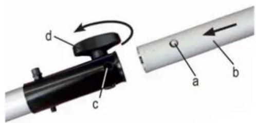
4.1. Shaft/bar assembly
- Push the lower part of the shaft (b) down until the stop pin (a) fits into the hole (c) in the shaft.
This is made easier if you slightly rotate the lower part of the shaft (b) in both directions.
The pin (a) will be in place when it is fully inserted into the hole.
- Finally, tighten the knob (d) securely.
4.2. Handlebar assembly
- Place the rubber cover of the left handle (3) on the shaft between the two arrow positioning labels, attach the upper handle (2) with the lower handle (4) to the tube with screws (1) and nuts (5) sufficiently tight.
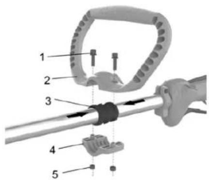
Caution
Do not tighten the screws until you have positioned the handlebars in the optimal working position. Always adjust the handlebar position with all accessories fully mounted.
4.3. Assembling the safe
natural_image
Three-panel black-and-white photo showing a mechanical assembly: a close-up of a mechanical component, a hand holding a tool, and a close-up of a mechanical clamp or bracket (no visible text or symbols)- Align the hole in the shield with the hole in the metal connector, insert the screw into the hole in the shield and the connector, and tighten it with the bolt.
Caution
Use only manufacturer-approved replacement parts and/or accessories. Failure to do so may result in malfunction, injury, and void the warranty. Never operate the machine without the guard installed.
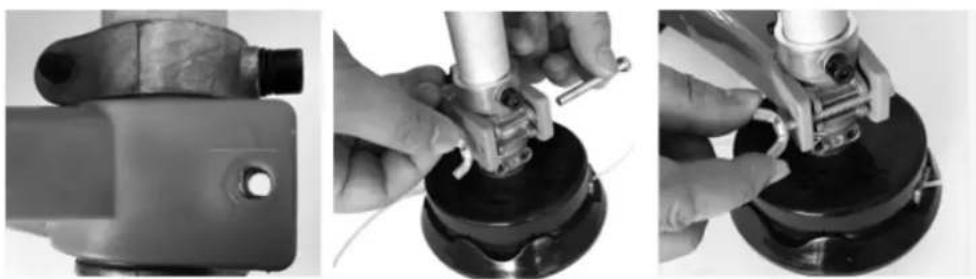
4.4. Disc protector assembly
- Insert the hex key into the hole to secure the connector, then place the nylon head onto the connector shaft and turn the nylon head clockwise until it is sufficiently tight.

natural_image
Mechanical component diagram showing a lever and base with motion arrows (no text or symbols)Warning
Ensure the cutting head is correctly mounted before use. The packaging is made from recycled materials. Dispose of the packaging in accordance with local regulations.
5. INSTRUCTIONS FOR USE
5.1. Before using
Always read the instruction manual carefully and check the machine before using it.
Make sure the handlebars and safety features are working properly. Never use a machine that is missing a part or has been modified outside of its specifications.
The casings must be correctly installed and in good condition before starting the machine.
Warning
Always wear safety gloves, leg and foot protection, and ear and eye protection. These must be CE marked and approved according to the PPE directive. Deficient equipment can reduce protection and lead to personal injury at work.
5.2. Fill the fuel tank
Warning
Fuel is dangerous. Turn off the engine and let it cool before refueling. You must observe all safety instructions regarding fuel handling.
The device is supplied without engine or gearbox oil. Before operating it, you must fill it with fuel.
Never use oil in 4-stroke engines or water-cooled 2-stroke engines. It could cause serious damage to the device.
Fuel mixtures that have remained unused for a month or more can clog the carburetor or cause engine malfunction. Store any remaining fuel in an approved container and keep it in a cool, dark place.
Mix regular grade gasoline (leaded or unleaded, alcohol-free) and a proven quality motor oil for air-cooled 2-stroke engines.
RECOMMENDED MIXING RATIO: GASOLINE 40: OIL 1
Warning
Monitor exhaust emissions. Always turn off the engine before refueling. Never refuel with the engine running or hot. Be careful of fire.
Never smoke while refueling and avoid inhaling gasoline fumes.
Carefully open the top of the tank, as pressure may have built up inside.
5.2.1. Before refueling
- Shake the fuel mixture container well.
- Place the machine on a flat, stable surface, with the fuel tank cap facing upwards.
- Clean the fuel tank cap and surrounding area to prevent dirt from entering the tank during filling.
- Carefully open the fuel tank cap to allow the internal pressure to gradually decrease.
- A funnel for filling and avoiding filling the tank to the brim.
- Unscrew the tank cap and remove it.
- Pour the fuel carefully, avoiding spills.
- Screw the tank cap firmly on by hand.
- Fill to the marked limit to avoid spilling fuel.

natural_image
Close-up of hands holding a black circular object with a 10x magnification device (no visible text or symbols)5.2.2. Fuel drain
- Place a container under the fuel drain screw.
- Unscrew the tank cap and remove it.
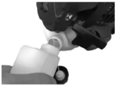
natural_image
Close-up of a mechanical device with a white plastic component inserted into a cylindrical port (no visible text or symbols)- Let the fuel run out completely.
- Screw the tank cap firmly on by hand.
Warning
Always close the fuel tank cap tightly. Immediately clean up any traces of fuel that may have fallen on the machine or the ground and do not start the engine until the gasoline fumes have dissipated.
5.3. Start-up
Do not start the unit until it is fully assembled. Before switching on the unit, always check the oil level and that all accessories are in place.
Warning
Risk of injury. Do not use the device unless you have detected any faults. If any part shows signs of wear or if the product has broken down, be sure to replace it before using the device again.
- Check the device for leaks.
- Check if the device has any visual defects.
- Check that all parts of the device are correctly installed.
- Check that all safety devices are in good working order.
Danger
Risk of injury. Before starting work, always check the floor and remove all objects.
Once the machine is set up correctly, start the motor as follows:
- Set the engine switch to the ON position, press throttle trigger B, throttle trigger A and the safety trigger until trigger A is half locked.

natural_image
Black handheld device with control panel and 'ON' label (no visible text or symbols on device body)Attention: The “O/I” switch will always remain in the “I” position, please change it to “O” manually if necessary.
EN
- Adjust the choke lever to the (off/ H).

natural_image
Close-up of a mechanical device with visible gears and buttons, no text or symbols present- Attention: When using and switching on the brushcutter for the first time, the end user is strongly recommended to operate the priming pump at least 10 times to obtain the best performance of the equipment also for future uses.
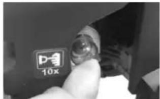
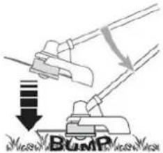
- Slowly pull the starter handle 10-15 cm until you feel some resistance, then pull it several times until you hear the engine turning, as shown in the image below.

natural_image
Close-up of hands using a screwdriver to adjust or install a mechanical component (no visible text or symbols)- Then adjust the choke lever to the (ON/III).

natural_image
Close-up of a mechanical device with visible gears and buttons, no text or symbols presentNote: Let the motor run for 1 minute to warm up before starting work.
- Pull the starter crank until the engine starts.

natural_image
Close-up of hands using a screwdriver to adjust or install a black mechanical component (no visible text or symbols)EN
-
Press the throttle triggers A and B, then the engine will idle, you can press trigger A to accelerate and operate.
-
If using a nylon cutter, before cutting, it is necessary to tap it against the feed line first.
- If you need to stop the cutting head from operating, release the throttle triggers A and B. If a problem occurs, press the motor switch; the machine will stop.

natural_image
Exterior view of a black handheld device with a labeled 'OFF' button (no other text or symbols visible)Warning
Do not use the machine for sweeping or tilt the cutting head. The engine's power could launch small objects and stones a great distance, causing injury or damage to people.

No person, except the operator, may enter the 15-meter radius danger zone. The operator must wear eye, hearing, face, foot, leg, and body protection.
People within the danger zone or at risk beyond it should wear eye protection against flying objects. The risk decreases with distance from the danger zone.
Attention
- Do not start the engine in long grass.
- When mowing the lawn, place the connection cable securely in pathways and in areas that have already been cut.
- When the engine has switched off, the nylon line will continue to run for several seconds, so do not approach the cutting head of the brushcutter until the nylon line has stopped completely.
6. MAINTENANCE AND CLEANING
Proper maintenance is essential for safe and efficient operation. It will also help reduce air pollution and extend the machine's lifespan.
The purpose of the maintenance and adjustment program is to keep the machine in the best operating condition.
EN
Turn off the engine before performing any maintenance. If it is necessary to run the engine, ensure the area is well ventilated. The exhaust contains carbon monoxide gas, which is harmful to your health.
Always select accessories recommended and approved by the manufacturer. Using other unapproved accessories and replacement parts may damage the machine. Remove safety devices after or during maintenance.
Before performing any maintenance or cleaning work, always turn off the engine.
- Do not spray the unit with water. Water ingress can damage the motor and electrical connection.
- Clean the unit with a cloth, hand brush, etc.
Attention
During maintenance operations:
- Remove the spark plug cap.
- Wait until the engine is cool enough.
- Never dispose of oils, fuel, or other polluting materials in unauthorized locations.
| Maintenance plan | |||
| 12 hours of use | 24 hours of use | 36 hours of use | |
| Air filter | Clean | Clean | Replace |
| Spark plug | Check | Clean | Replace |
Expert inspection is required:
a) If the brushcutter hits an object.
b) If the engine suddenly stops
c) If the nylon cutter is damaged.
d) If the nylon head connector is damaged.
At the end of the season, the nylon reel must be replaced and cleaned. It should always be cleaned or, if necessary, replaced with a new one. This cleaning or replacement service must always be performed by a customer service center.
6.1. Cleaning
- Keep your machine clean. The exterior of the machine can be wiped with a soft cloth dampened with mild detergent if necessary. Never use water to clean the machine, as it may damage the internal parts.
- Some maintenance products and solvents can damage plastic parts, so be careful.
- To reduce engine damage, periodically clean the slots with compressed air and clear the exhaust area to remove sawdust, twigs, leaves, or other debris.
- Take special care to keep the ventilation inlets/outlets free of obstructions. Cleaning with a soft brush followed by a blast of compressed air is usually sufficient to ensure acceptable internal cleanliness.
- Wear eye protection when cleaning.
Starter unit
To prevent overheating and engine damage, always keep the ventilation grilles clean and free of sawdust and debris. If you notice any signs of wear on the starter cable, contact your dealer for replacement.
Nuts and bolts
Periodically check that all nuts and bolts are tight and that the handles are securely attached.
6.2. Air filter
▲ Important
Cleaning the air filter is essential to ensure the machine's efficiency and longevity. Do not operate with a damaged or missing filter, as this could permanently damage the motor.
Clean the filter as follows:
- Loosen the knob, remove the cap and the filter.
- Clean the filter with soapy water. Do not use gasoline or other solvents.
- Leave the filter to dry in the open air.
- Replace the filter and lid, tightening the knob again.
Note: Never run the engine without the air filter installed.

natural_image
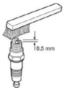
Close-up of a hand using a tool to adjust or install a mechanical component, showing no visible text or symbols.6.3. Spark plug
- Periodically, remove and clean the spark plug with a wire brush to remove any deposits.
- Check and adjust the correct distance between the electrodes.
- Replace the spark plug and tighten it securely using the supplied wrench.
- The spark plug must be replaced with one of the same characteristics whenever the electrodes have burned out or the insulation has worn out, and in any case every 100 hours of operation.
6.4. Sharpening the nylon cutting blade
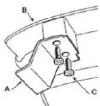
- Remove the blade (A) from the guard (B) by removing the screws (C).
- Secure the cutting blade in a vise and sharpen it with a flat file, taking care to maintain the original cutting angle.
- Reassemble the blade into the guard.
7. STORAGE
At the end of each work session, carefully clean the machine of dust and debris, and ensure that no parts are damaged; replace any defective parts. Store the machine in a dry place, protected from the elements, and with the cover properly in place.
Warning
When transporting the machine in a car, first completely empty the fuel tank to prevent leaks.
Store the machine, operating instructions, and any accessories in the original packaging. This way, you'll always have all the information and parts readily available.
Pack the product securely or use the original packaging to prevent damage during shipping. Wear protective gloves when handling cutting discs or accessories.
Keep the disk protection device activated, except when directly working on the disk.
Store the machine in a dry, well-ventilated place with an empty fuel tank. Do not store fuel near the machine.
7.1.1. Nylon replacement
Stop the engine and follow the sequence below.
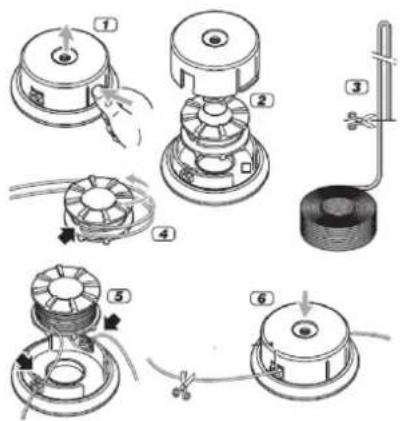
Warning
Never use cutting accessories not recommended by the manufacturer. Unapproved cutting accessories can cause serious injury during use.
8. TROUBLESHOOTING
Warning
Danger of injury if the motor starts suddenly. Protect yourself against injury. Before performing any work on this product:
- Turn off the engine.
- Remove the ignition key.
EN
- Wait until all moving parts have stopped and the engine has cooled completely.
-
Disconnect the spark plug connector from the engine to prevent the engine from starting suddenly.
-
The engine does not start or does not stay running.
-
Reassemble the nylon cutter.
- Check if there is no fuel or if it has run out.
- Incorrect start procedure: follow the instructions.
- Dirty spark plug or incorrect electrode gap: check the spark plug.
- Air filter clogged: clean or replace the filter.
-
Carburetor problems: contact your dealer
-
The engine starts but lacks power.
- Request a replacement of the nylon reel (customer service center)
- Air filter clogged: clean or replace the filter.
Carburetor problems: contact your dealer
-
The engine runs erratically and loses power when accelerating.
-
Dirty spark plug or incorrect gap between electrodes
- Check the spark plug
- Carburetor problems
-
Contact your distributor
-
The engine produces too much smoke.
-
Incorrect fuel mixture composition - Prepare the fuel mixture according to the instructions.
-
Carburetor problems: contact your dealer
-
The cutting device must not be moved when the engine is idling.
- Incorrect carburetor adjustment - Contact your dealer
- The machine begins to vibrate abnormally.
- Damaged or loose parts: Stop the machine and disconnect the spark plug wire. Inspect for damage. Check and tighten any loose parts. All servicing, repairs, and replacements must be carried out only by an authorized service center.
-
If the temperature of the machines is too high:
-
Make sure the machines rest at regular times.
- Faults that cannot be corrected with the help of this table can only be corrected by a specialized company (customer service center).
9. WARRANTY
If your product suffers any manufacturing defect during the established warranty period, please contact or go directly to your point of sale with the necessary documentation.
Your purchase receipt should be kept as proof of the purchase date. Your tool must be returned to your distributor in acceptable and clean condition, in its original molded case, if applicable, along with your corresponding proof of purchase.
9.1. Warranty period
The legal warranty period for the product begins on the original date of purchase by the first initial buyer and its duration will be that established by the Royal Decree-Law on the protection of consumers and users against situations of social and economic vulnerability of the year corresponding to the time of acquisition of the product.
Some countries do not have limitations on how long an implied warranty lasts or do not allow the exclusion or limitation of consequential or incidental damages, in which case the above limitation and exclusion may not apply to you. This warranty gives you specific legal rights, and you may also have other rights that vary from state to state or country to country.
9.2. Exclusions
This warranty does not cover product damage or performance problems caused by:
- Natural wear and tear from use.
- Misuse, negligence, careless operation, or lack of maintenance.
- Defects caused by improper use, damage caused by handling by personnel not authorized by Anova or use of non-original spare parts.
- Defects in normal wear parts, such as bearings, brushes, cables, plugs or accessories such as drills, drill bits, saw blades, etc.
- Damage or defects resulting from abuse, accidents, or alterations.
- Incorrect use and storage (explicit reference to the fact that the rules described in the operating instructions have not been followed).
- Wear and tear caused by the customer (e.g., broken saw blades, consumed carbon brushes, etc.).
- Wear and secondary damage due to lack of maintenance, repair, lubricants (e.g., overheating damage due to blocked cooling slots, bearing damage as a result of dirt, frost damage, etc.)
- Damage as an obvious result of overuse/overload.
- Damage caused by inappropriate supplies (e.g., incorrect fuel)
- Load-induced breakage of housing components or accessories due to abnormal stress
- Load-induced deformation of the housing components or accessories due to abnormal stress.
- Damage resulting from the operation of supplies that are overfilled or leak due to improper storage, improper cleaning agents, or other damaging chemical components.
- Damage due to improper exposure to extreme temperatures (e.g., frost cracking, thermal deformation of components, etc.)
- Damage from permanent exposure to ultraviolet radiation.
- Damage caused by inadequate maintenance.
- Any damage caused by failure to follow the instructions in the instruction manual
- Any product that has been repaired by an unqualified professional.
- Any product connected to an unsuitable power source (amps, voltage, frequency).
- Any damage caused by external influences (water, chemicals, physical, impacts) or foreign substances.
- Use of unsuitable accessories or parts.
- It does not cover defects in normal wear and tear parts, nor does it cover damage or defects resulting from abuse, accidents or alterations, nor transportation costs.
Furthermore, the warranty is voided if the product has been altered or modified, or if the trademark/serial number of the machine has been defaced or removed.
Routine maintenance, tuning, adjustments, or normal wear and tear are not covered under this warranty. This manual does not cover all possible warranty exclusions; for more information, please contact your nearest Anova dealer.
9.3. In case of incident
The warranty must be correctly completed with all the requested information and accompanied by the purchase invoice.
Anova reserves the right to refuse any claim where the purchase cannot be verified or where it is clear that the product was not properly maintained (maintenance, clean ventilation slots, lubrication, regularly maintained carbon brushes, cleaning, storage, etc.).
Private use is defined as personal domestic use by an end consumer. Commercial use, on the other hand, means all other uses, including uses for business purposes, income generation, or rental. Once the product has been used for commercial purposes, it will be considered a commercial product thereafter for the purposes of this warranty.
These are our standard warranty terms, but occasionally there may be additional warranty coverage not specified at the time of publication. For more information, please contact your nearest authorized Anova dealer or visit www.millasur.com.
Warranty service is only available through authorized Anova distributors. You can find your nearest distributor on our distributor map at www.anova.es.
10. ENVIRONMENT


It is essential to ensure that products and their components are disposed of responsibly to protect the environment. Below, you will find general guidelines for the proper disposal of various materials used in your machine.
Dispose of your machine in an environmentally friendly way. We shouldn't throw machines away with the regular household waste. Their plastic and metal components can be sorted according to their type and recycled.
When disposing of machinery or metal products, it's important to remember that their metal components, such as iron, steel, or aluminum, must be properly recycled at metal recycling facilities. This will contribute to their potential reuse in the manufacture of new products.
Oils and Fuels
Used oils and fuels, among other things, must be recycled properly. Do not pour these liquids down drains, into soil, rivers, lakes, or seas, as they can cause serious environmental damage. Take them to a recycling center or specialized collection point. This process helps prevent water and soil contamination and allows for the safe reuse of oils, if possible.
Plastics
Plastics should be separated and taken to designated recycling points. Do not throw them away with regular household waste. Plastics can be recycled, helping to reduce waste.
Cardboard
Packaging materials, such as cardboard, are recyclable. Be sure to separate clean, dry cardboard and place it in designated recycling containers or at an official waste collection point. Do not dispose of it with household waste.
Batteries
Batteries and other electronic components from machines must be disposed of at designated collection points to prevent the release of toxic substances into the environment. Do not throw them away with regular trash. Take them to appropriate recycling centers for safe and responsible handling.
By following these guidelines, you contribute to environmental protection and resource conservation. For more information on material disposal and recycling, please contact your local authorities and consult the necessary information.
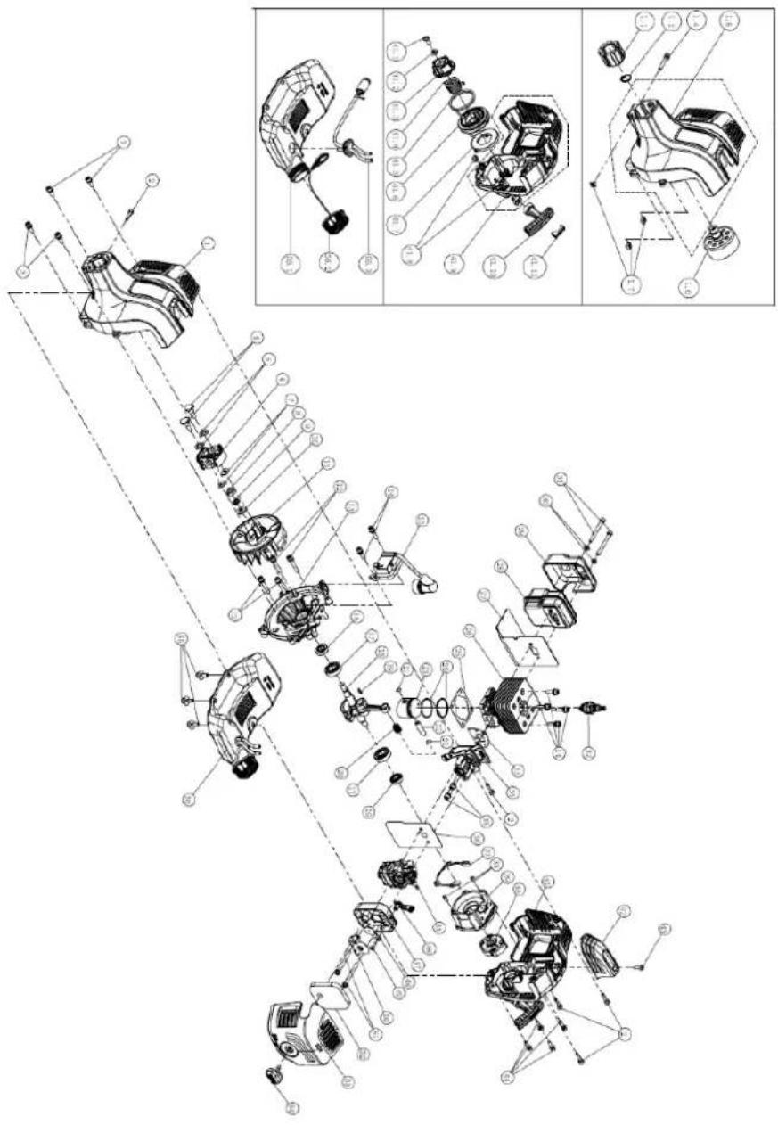
11. EXPLODED VIEW
12. CE CERTIFICATE
DISTRIBUTION COMPANY
MILLASUR, SL
CE DECLARATION OF CONFORMITY
In compliance with the various EC directives, this document confirms that, due to its design and construction, and as indicated by the CE marking affixed by the manufacturer, the machine identified herein meets the relevant and fundamental health and safety requirements of the aforementioned EC directives. This declaration authorizes the product to display the CE marking.
In the event that the machine is modified and this modification is not approved by the manufacturer and communicated to the distributor, this declaration will lose its value and validity.
Machine name: BRUSH CUTTER
Model: D525C
Recognized and approved standard to which it conforms:
Directive 2006/42/EC
2014/30/EU
Tested in accordance with regulations:
EN ISO 11806-1:2011
EN ISO 14982:2009
Company seal
MILLASUR, S.L.U.
Rúa Eduardo Pondal,23 - Pol.Emp..Sigüeiro
15688-Oroso-A Coruña
Tel.(+34) 981 69 64 65 · Fax (+34) 981 69 08 61
e-mail: millasur@millasur.com
CIF: B-15 749 922
20/10/2025
Freischneider
D525C
ANOVA®
natural_image
Black and white photo of a manual lawn brush tool with adjustable handle and head (no visible text or symbols)DE
ANOVA®
Vorsicht
natural_image
Three-panel black-and-white photo showing mechanical assembly steps: tool, hand holding component, and close-up of a black circular component (no visible text or symbols)natural_image
Mechanical component diagram showing a lever and base with motion arrow (no text or symbols)⚠ Warning
natural_image
Close-up of a hand holding a black circular object with a D-10x 10x label (no readable text or symbols beyond branding)natural_image
Close-up of a mechanical device with a white component and black components, no visible text or symbolsnatural_image
Black handheld device with a control panel and 'ON' label, no visible text or symbols on the device itself.natural_image
Close-up of a mechanical device with visible gears and housing (no text or symbols)natural_image
Close-up of a finger pressing a button labeled '10x' with a small icon, no readable text or symbols beyond the label.natural_image
Close-up of hands using a screwdriver to adjust or install a mechanical component (no visible text or symbols)natural_image
Close-up of a mechanical device with visible gears and buttons, no text or symbols presentnatural_image
Close-up of hands using a screwdriver to adjust or install a mechanical component (no visible text or symbols)natural_image
Black handheld device with a button labeled 'OFF' (no other text or symbols visible)⚠ Warning
natural_image
Close-up of a hand using a tool to adjust or install a mechanical component, shown from two different angles (no text or symbols visible)6.3. Zündkerze
⚠ Warning
12. CE-ZERTIFIKAT
natural_image
Black and white photo of a manual lawn brush tool with adjustable handle and head (no visible text or symbols)NL
ANOVA®
ANDERE WAARSCHUWINGEN:
3. PRODUCTBESCHRIJVING

- Bougie
- Luchtfilterdeksel
- Chokehendel
- Brandstoftankdop
- Opstarten
- Brandstoftank
-
Achterklep
-
Achterste handgreep
- Voorste handgreep
- As
- Beschermer
- Snijkop
- Asconnector
4. MONTAGE
⚠ Waarschuwing
4.2. Stuurmontage
⚠️ Voorzichtigheid
natural_image
Three-panel black-and-white photo showing a mechanical assembly: a tool on a component, hands adjusting a clamp or fixture, and a close-up of the clamping device (no visible text or symbols)natural_image
Mechanical component diagram showing a lever and base with motion arrows (no text or symbols)⚠ Waarschuwing
natural_image
Close-up of a hand holding a black cylindrical object with a D-gel (10x) label, no visible text or symbols on the object itself.5.2.2. Brandstofafvoer
natural_image
Close-up of a mechanical device with a white component and black components, no visible text or symbolsnatural_image
Black handheld device with control buttons and a 'ON' label (no visible text or symbols on the device itself)natural_image
Close-up of a mechanical device with no visible text or symbolsnatural_image
Close-up of a finger pressing a small glass lens on a dark surface, with a 10x label visible (no readable text beyond the label)natural_image
Close-up of hands using a screwdriver to adjust or install a mechanical component (no visible text or symbols)natural_image
Close-up of a mechanical device with visible gears and buttons, no text or symbols presentnatural_image
Close-up of hands using a screwdriver to adjust or install a black mechanical component (no visible text or symbols)natural_image
Black handheld device with a button labeled 'OFF' (no other text or symbols visible)⚠ Waarschuwing
natural_image
Close-up of hands holding a black plastic device with ventilation slots (no visible text or symbols)
natural_image
Close-up of a mechanical assembly with no visible text or symbols6.3. Bougie
⚠ Waarschuwing
8. PROBLEEMOPLOSSING
⚠ Waarschuwing
12. CE-CERTIFICAAT
DISTRIBUTIEBEDRIJF
MILLASUR, SL