EX650T - Excavator Anova - Free user manual and instructions
Find the device manual for free EX650T Anova in PDF.

| Product type | Excavator (mini excavator) |
| Brand | Anova |
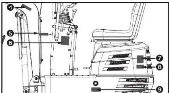
| Model | EX650T |
| Operating weight | 637 kg |
| Engine | Petrol, 306 cm³ |
| Standard bucket volume | 0.011 m³ |
| Digging force (bucket) | 8.8 kN |
| Rotation speed | 9.3 rpm |
| Travel speed | 1.7 km/h |
| Gradeability | 15° |
| Ground pressure | 26.5 kPa |
| Hydraulic pressure | 17.5 MPa |
| Hydraulic tank capacity | 12 L |
| Fuel tank capacity | 6 L |
| Tracks | Rubber tracks |
| Sound level (at operator station) | 82.5 dB (K=4 dB) |
| Vibration (arm) | 2.17 m/s² (K=0.5) |
| Vibration (body) | 7.65 m/s² (K=0.5) |
| Arm rotations | Left 70°, Right 70° |
| Main functions | Digging, lifting, grading, rotation, travel |
| Routine maintenance | Daily checks: levels, filters, lubrication; engine oil change every 50 h |
| Safety | Hydraulic brake, rotation lock, fire extinguisher recommended, PPE mandatory |
| Spare parts | Available from Anova authorized dealer; filters, spark plugs, belts, seals |
| Warranty | Complies with legislation; duration varies by country; exclusions for normal wear |
Frequently Asked Questions - EX650T Anova
User questions about EX650T Anova
0 question about this device. Answer the ones you know or ask your own.
Ask a new question about this device
Download the instructions for your Excavator in PDF format for free! Find your manual EX650T - Anova and take your electronic device back in hand. On this page are published all the documents necessary for the use of your device. EX650T by Anova.
USER MANUAL EX650T Anova
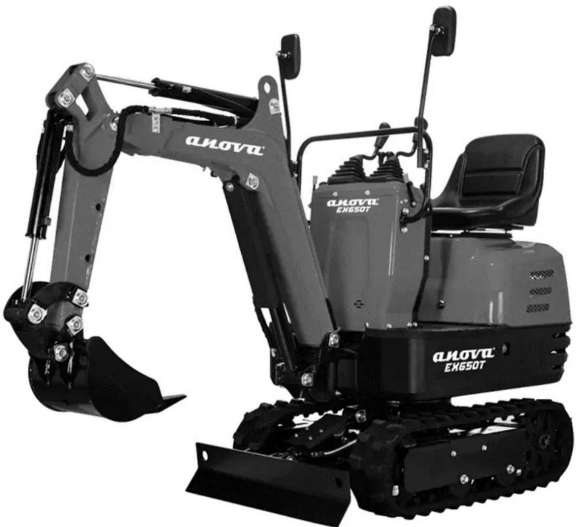
natural_image
Exterior view of a black and gray DNOVA EK650T excavator with tracked tracks (no visible text or symbols on the device body)ES
ANOVA®
natural_image
Two identical diagrams showing mechanical components with no visible text, numbers, or symbols.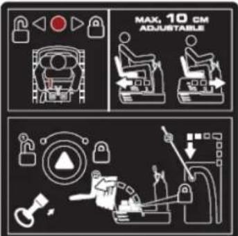
natural_image
Illustration of a hand holding a smartphone with magnifying glass examining a device (no text or symbols)Tubo manual
flowchart
graph TD
    A["1: Robot Arm"] --> B["2: Robot Arm"]
    B --> C["3: Control Panel"]
    C --> D["4: Robot Arm"]
    D --> E["5: Robot Arm"]
    E --> F["6: Robot Arm"]
    F --> G["7: Robot Arm"]
    G --> H["8: Robot Arm"]
    H --> I["9: Robot Arm"]
    I --> J["10: Robot Arm"]
    J --> K["11: Robot Arm"]
    K --> L["12: Robot Arm"]
    L --> M["13: Robot Arm"]
    M --> N["14: Robot Arm"]
    N --> O["15: Robot Arm"]
    O --> P["16: Robot Arm"]
    P --> Q["17: Robot Arm"]
    Q --> R["18: Robot Arm"]
    R --> S["19: Robot Arm"]
    S --> T["20: Robot Arm"]
natural_image
Line drawing of an excavator on a utility pole, no text or symbols presentnatural_image
Technical line drawing of an excavator on a construction site (no text or symbols)natural_image
Technical line drawing of a vehicle chassis with labeled sections A and B (no text or symbols on the diagram itself)A. Parte delantera
B. Parte trasera
natural_image
Technical line drawing of an excavator with tracked arm and base mount (no text or symbols)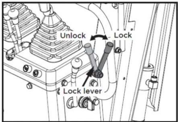
1

2

3

4
5

6

7

8
9


10

flowchart
graph TD
    A["Robot Arm"] --> B["Control Unit"]
    C["Engine Mount"] --> D["Control Unit"]
    E["Drain Arm"] --> F["Control Unit"]
    G["Hybrid Mechanism"] --> H["Control Unit"]
    I["Hybrid Mechanism"] --> J["Control Unit"]
    K["Hybrid Mechanism"] --> L["Control Unit"]
    M["Hybrid Mechanism"] --> N["Control Unit"]
    O["Hybrid Mechanism"] --> P["Control Unit"]
    Q["Hybrid Mechanism"] --> R["Control Unit"]
    S["Hybrid Mechanism"] --> T["Control Unit"]
    U["Hybrid Mechanism"] --> V["Control Unit"]
    W["Hybrid Mechanism"] --> X["Control Unit"]
    Y["Hybrid Mechanism"] --> Z["Control Unit"]
11


12

13
17

flowchart
graph TD
    A["Robot"] --> B["Lock"]
    C["Robot"] --> D["Lock"]
    E["Robot"] --> F["Lock"]
    G["Robot"] --> H["Lock"]
    I["Robot"] --> J["Lock"]
    K["Robot"] --> L["Lock"]
    M["Robot"] --> N["Lock"]
    O["Robot"] --> P["Lock"]
    Q["Robot"] --> R["Lock"]
    S["Robot"] --> T["Lock"]
    U["Robot"] --> V["Lock"]
    W["Robot"] --> X["Lock"]
    Y["Robot"] --> Z["Lock"]
    AA["Robot"] --> AB["Lock"]
    AC["Robot"] --> AD["Lock"]
    AE["Robot"] --> AF["Lock"]
    AG["Robot"] --> AH["Lock"]
    AI["Robot"] --> AJ["Lock"]
    AK["Robot"] --> AL["Lock"]
    AM["Robot"] --> AN["Lock"]
    AO["Robot"] --> AP["Lock"]
    AQ["Robot"] --> AR["Lock"]
    AS["Robot"] --> AT["Lock"]
    AU["Robot"] --> AV["Lock"]
    AW["Robot"] --> AX["Lock"]
    AY["Robot"] --> AZ["Lock"]
    BA["Robot"] --> BB["Lock"]
    BC["Robot"] --> BD["Lock"]
    BE["Robot"] --> BF["Lock"]
    BG["Robot"] --> BH["Lock"]
    BI["Robot"] --> BJ["Lock"]
    BK["Robot"] --> BL["Lock"]
    BM["Robot"] --> BN["Lock"]
    BO["Robot"] --> BP["Lock"]
    BQ["Robot"] --> BR["Lock"]
    BS["Robot"] --> BT["Lock"]
    BU["Robot"] --> BV["Lock"]
    BW["Robot"] --> BX["Lock"]
    BY["Robot"] --> BZ["Lock"]
    CA["Robot"] --> CB["Lock"]
    CC["Robot"] --> CD["Lock"]
    CE["Robot"] --> CF["Lock"]
    CG["Robot"] --> CH["Lock"]
    CI["Robot"] --> CJ["Lock"]
14
18
15

16

4.2. Montaje
natural_image
Technical line drawing of a vehicle's seat assembly and maintenance mechanism (no text or symbols)natural_image
Technical line drawing of a mechanical device with labeled component A (no text or symbols beyond label)A: Interruptor de bocina
▲Importante
natural_image
Technical line drawing of a mechanical device with labeled components and an arrow pointing to component A (no text or symbols beyond basic labels)natural_image
Technical line drawing of a mechanical device with labeled component A (no text or symbols beyond label)natural_image
Technical line drawing of a mechanical assembly with no visible text or symbolsnatural_image
Technical diagram of a piping system with valve and valve components (no text or labels)
natural_image
Technical line drawing of an excavator assembly with no visible text or symbols▲ Importantante
natural_image
Technical diagram of a mechanical or electrical component with pipe connections and a highlighted section showing a downward arrow (no text or symbols present)
natural_image
Technical line drawing of an excavator and tracked vehicle (no text or symbols)natural_image
Technical diagram of a piping system with valves and valves, showing internal components and directional arrows (no text or labels)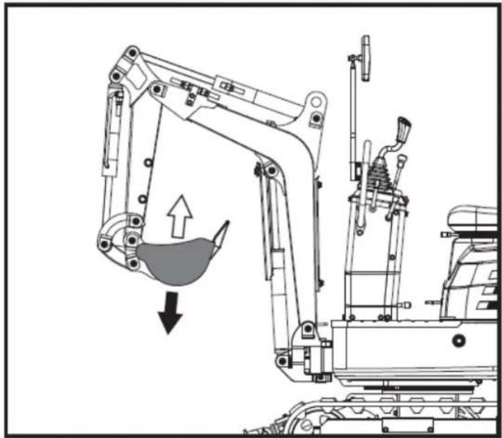
natural_image
Technical line drawing of an excavator with a downward load arrow, showing mechanical components without any text or symbols.natural_image
Technical diagram of a mechanical or electrical component with pipes and a central fan-like structure, no visible text or symbols.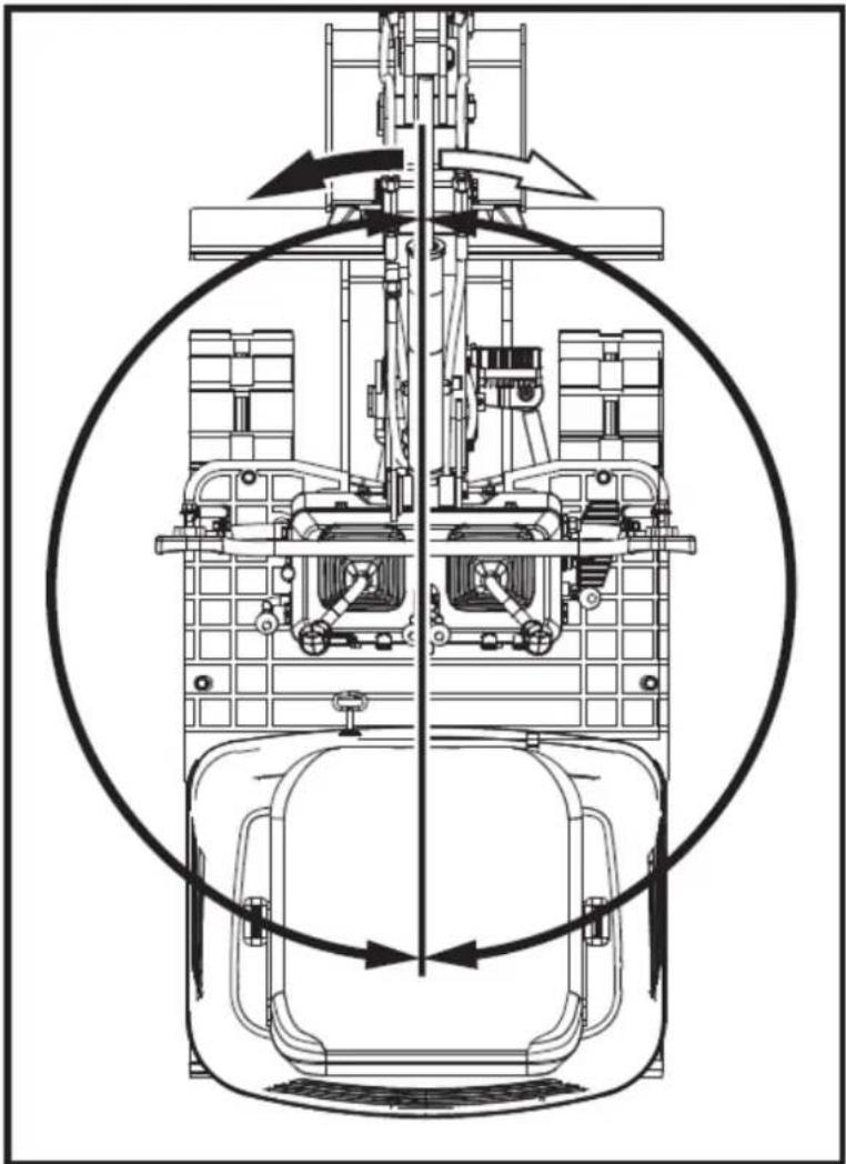
natural_image
Technical line drawing of a mechanical assembly with internal components and directional arrows (no text or symbols)natural_image
Technical line drawing of a mechanical device with no visible text or symbols
natural_image
Technical diagram of a mechanical assembly with directional arrows indicating motion (no text or symbols)natural_image
Technical line drawing of a robotic excavator with labeled component A, showing mechanical assembly and ground-level reference (no text or symbols beyond label)natural_image
Technical line drawing of two excavators on a construction ground, showing different mechanical configurations (no text or symbols present)▲ Importantante
natural_image
Line drawing of a bulldozer with a cross symbol crossed out, no text or symbols present5.5.2. Giros
▲ Importante
natural_image
Technical diagram showing a mechanical assembly with an arrow indicating rotational motion (no text or symbols present)natural_image
Line drawing of an excavator on a construction ground (no text or symbols)natural_image
Technical line drawing of an excavator on a slope, showing mechanical components and no text or symbolsA. Cuña
natural_image
Line drawing of a construction vehicle with an excavator on an inclined plane (no text or symbols)Peligro
natural_image
Illustration of a truck with a worker kneeling beside it, showing structural damage or damage (no text or symbols)natural_image
Line drawing of an excavator on a flatbed truck, no text or symbols presentnatural_image
Cartoon illustration of a front-end loader dumping material into a pile of waste (no text or symbols)natural_image
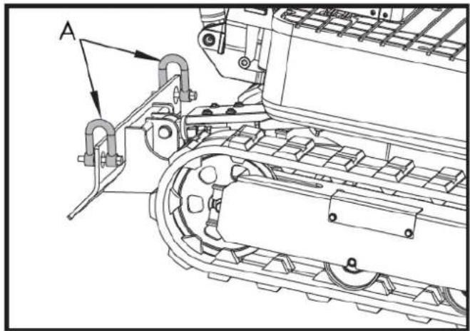
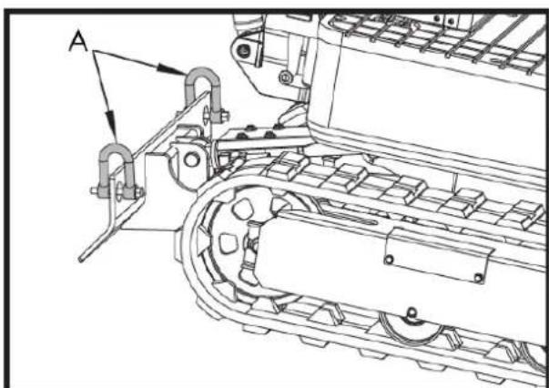
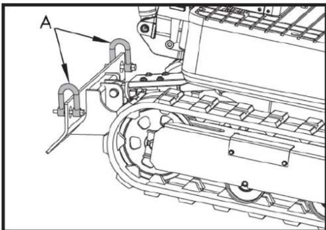
Technical line drawing of a tracked excavator with labeled component A (no text or symbols beyond label)A. Grillete
natural_image
Technical line drawing of a tracked vehicle with conveyor belt and mechanical components (no text or symbols)A. Grillete

6. MANTENIMIENTO
natural_image
Technical line drawing of a mechanical assembly with labeled component A (no text or symbols beyond label)natural_image
Technical line drawing of a mechanical assembly with labeled component A (no readable text or symbols)natural_image
Technical line drawing of an electric motor assembly with labeled components (no text or symbols present)natural_image
Technical line drawing of a tank interior showing engine, chassis, and structural components (no text or labels)natural_image
Technical line drawing of a tracked vehicle with visible tracks and structural components (no text or symbols)
natural_image
Technical line drawing of a mechanical assembly with labeled component A (no text or symbols beyond label)natural_image
Technical line drawing of a tracked vehicle with labeled component A (no text or symbols beyond label)natural_image
Silhouette of a human head with an eyepatch and motion arrows indicating speed or effort (no text or symbols)natural_image
Illustration of a hand using a tool to mark a grid on a rectangular object (no text or symbols)▲ Importante
natural_image
Technical line drawing of a vehicle engine bay with labeled component 'A' (no text or symbols beyond label)natural_image
Technical line drawing of a tracked vehicle with labeled component A (no text or symbols beyond label)A. Engrasador
natural_image
Technical line drawing of a tracked vehicle with labeled component A (no text or symbols beyond label)natural_image
Technical line drawing of a tracked vehicle with labeled component A (no text or symbols beyond label)A. Tapón de drenaje
A. Tornillo M20x120
B. Tuerca M20
C. Llave inglesa de 30 mm
natural_image
Technical line drawing of an excavator with attached boom and tracked vehicle (no text or symbols)
A. Unión
Importante
natural_image
Technical line drawing of a mechanical assembly with labeled components (A and B), no readable text or symbols present.A. Fusible

B. Caja de fusibles
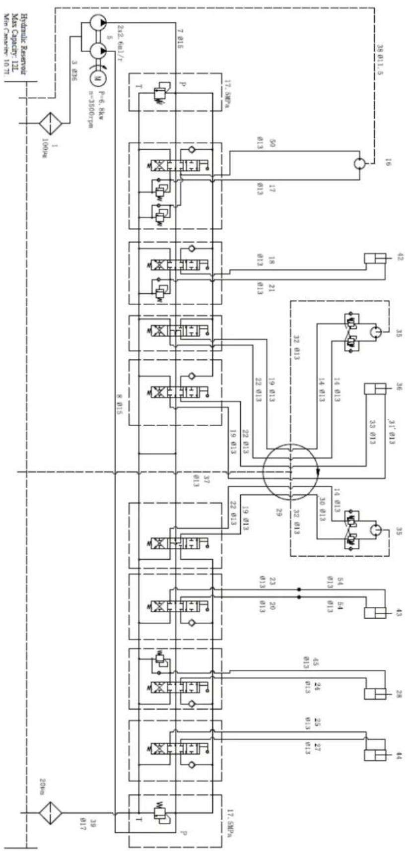
Diagrama sistema hidráulico

flowchart
graph TD
    A["100Pc"] --> B["3.836"]
    B --> C["2x2.6x1/T"]
    C --> D["7.015"]
    C --> E["17.5xPc"]
    C --> F["17.5xPm"]
    C --> G["17.5xPm"]
    C --> H["17.5xPm"]
    C --> I["17.5xPm"]
    C --> J["17.5xPm"]
    C --> K["17.5xPm"]
    C --> L["17.5xPm"]
    C --> M["17.5xPm"]
    C --> N["17.5xPm"]
    C --> O["17.5xPm"]
    C --> P["17.5xPm"]
    C --> Q["17.5xPm"]
    C --> R["17.5xPm"]
    C --> S["17.5xPm"]
    C --> T["17.5xPm"]
    C --> U["17.5xPm"]
    C --> V["17.5xPm"]
    C --> W["17.5xPm"]
    C --> X["17.5xPm"]
    C --> Y["17.5xPm"]
    C --> Z["17.5xPm"]
    C --> AA["17.5xPm"]
    C --> AB["17.5xPm"]
    C --> AC["17.5xPm"]
    C --> AD["17.5xPm"]
    C --> AE["17.5xPm"]
    C --> AF["17.5xPm"]
    C --> AG["17.5xPm"]
    C --> AH["17.5xPm"]
    C --> AI["17.5xPm"]
    C --> AJ["17.5xPm"]
    C --> AK["17.5xPm"]
    C --> AL["17.5xPm"]
    C --> AM["17.5xPm"]
    C --> AN["17.5xPm"]
    C --> AO["17.5xPm"]
    C --> AP["17.5xPm"]
    C --> AQ["17.5xPm"]
    C --> AR["17.5xPm"]
    C --> AS["17.5xPm"]
    C --> AT["17.5xPm"]
    C --> AU["17.5xPm"]
    C --> AV["17.5xPm"]
    C --> AW["17.5xPm"]
    C --> AX["17.5xPm"]
    C --> AY["17.5xPm"]
    C --> AZ["17.5xPm"]
    C --> BA["17.5xPm"]
    C --> BB["17.5xPm"]
    C --> BC["17.5xPm"]
    C --> BD["17.5xPm"]
    C --> BE["17.5xPm"]
    C --> BF["17.5xPm"]
    C --> BG["17.5xPm"]
    C --> BH["17.5xPm"]
    C --> BI["17.5xPm"]
    C --> BJ["17.5xPm"]
    C --> BK["17.5xPm"]
    C --> BL["17.5xPm"]
    C --> BM["17.5xPm"]
    C --> BN["17.5xPm"]
    C --> BO["17.5xPm"]
    C --> BP["17.5xPm"]
    C --> BQ["17.5xPm"]
    C --> BR["17.5xPm"]
    C --> BS["17.5xPm"]
    C --> BT["17.5xPm"]
    C --> BU["17.5xPm"]
    C --> BV["17.5xPm"]
    C --> BW["17.5xPm"]
    C --> BX["17.5xPm"]
    C --> BY["17.5xPm"]
    C --> BZ["17.5xPm"]
    C --> CA["17.5xPm"]
    C --> CB["17.5xPm"]
    C --> CC["17.5xPm"]
    C --> CD["17.5xPm"]
    C --> CE["17.5xPm"]
    C --> CF["17.5xPm"]
    C --> CG["17.5xPm"]
    C --> CH["17.5xPm"]
    C --> CI["17.5xPm"]

7. ACCESORIOS OPCIONALES
natural_image
Line drawing of an excavator with levers and bucket (no text or symbols)7.2. Rastrillo
natural_image
Technical line drawing of an excavator with tracked blade and bucket (no text or symbols)7.2.1. Instalación rastrillo
natural_image
Technical line drawing of an excavator and tracked vehicle (no text or symbols)natural_image
Line drawing of an excavator with tracked base and attached levers (no text or symbols)7.4. Garra
natural_image
Line drawing of an excavator with tracked base and mechanical components (no text or symbols)natural_image
Line drawing of an excavator with attached mechanical components (no text or symbols)natural_image
Technical line drawing of an excavator assembly (no text or symbols present)natural_image
Line drawing of an excavator with tracked track and blade assembly (no text or symbols)natural_image
Technical line drawing of an excavator with tracked base and bucket, no text or symbols present7.6. Cubierta
natural_image
Technical line drawing of an excavator with tracked base and attached boom (no text or symbols)natural_image
Line drawing of an excavator with tracked track and mechanical components (no text or symbols)natural_image
Technical line drawing of an excavator with tracked base and attached levers (no text or symbols)ES

12. CERTIFICADO CE
natural_image
Exterior view of a black and gray DNOVA EX6SOT excavator with tracked tracks (no visible text or symbols on the device body)PT
ANOVA®
natural_image
Three identical diagrams showing mechanical components with no visible text or symbols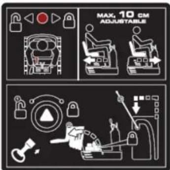
natural_image
Illustration of a hand holding a smartphone with magnifying glass examining a device (no text or symbols)Tubo manual

flowchart
graph TD
    A["1: Robot Arm"] --> B["2: Robot Arm"]
    B --> C["3: Control Panel"]
    C --> D["4: Robot Arm"]
    D --> E["5: Robot Arm"]
    E --> F["6: Robot Arm"]
    F --> G["7: Robot Arm"]
    G --> H["8: Robot Arm"]
    H --> I["9: Robot Arm"]
    I --> J["10: Robot Arm"]
    J --> K["11: Robot Arm"]
    K --> L["12: Robot Arm"]
    L --> M["13: Robot Arm"]
    M --> N["14: Robot Arm"]
    N --> O["15: Robot Arm"]
    O --> P["16: Robot Arm"]
    P --> Q["17: Robot Arm"]
    Q --> R["18: Robot Arm"]
    R --> S["19: Robot Arm"]
    S --> T["20: Robot Arm"]
natural_image
Line drawing of an excavator on a utility pole with power lines and a crane (no text or symbols)natural_image
Technical line drawing of an excavator on a construction site (no text or symbols)natural_image
Technical line drawing of a vehicle chassis with labeled sections A and B (no text or symbols on the diagram itself)A. Frente B. Traseira
natural_image
Technical line drawing of an excavator with tracked arm and base mount (no text or symbols)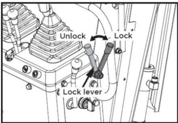

natural_image
Line drawing of a dump truck with an excavator on its side, no text or symbols present1

2
3

4

5

6
7

8

9

10

flowchart
graph TD
    A["Robot Arm"] --> B["Control Unit"]
    C["Engine Mount"] --> D["Control Unit"]
    E["Drain Arm"] --> F["Control Unit"]
    G["Hybrid Mechanism"] --> H["Control Unit"]
    I["Hybrid Mechanism"] --> J["Control Unit"]
    K["Hybrid Mechanism"] --> L["Control Unit"]
    M["Hybrid Mechanism"] --> N["Control Unit"]
    O["Hybrid Mechanism"] --> P["Control Unit"]
    Q["Hybrid Mechanism"] --> R["Control Unit"]
    S["Hybrid Mechanism"] --> T["Control Unit"]
    U["Hybrid Mechanism"] --> V["Control Unit"]
    W["Hybrid Mechanism"] --> X["Control Unit"]
    Y["Hybrid Mechanism"] --> Z["Control Unit"]
11
12

13

17

flowchart
graph TD
    A["Robot"] --> B["Lock"]
    C["Robot"] --> D["Lock"]
    E["Robot"] --> F["Lock"]
    G["Robot"] --> H["Lock"]
    I["Robot"] --> J["Lock"]
    K["Robot"] --> L["Lock"]
    M["Robot"] --> N["Lock"]
    O["Robot"] --> P["Lock"]
    Q["Robot"] --> R["Lock"]
    S["Robot"] --> T["Lock"]
    U["Robot"] --> V["Lock"]
    W["Robot"] --> X["Lock"]
    Y["Robot"] --> Z["Lock"]
    AA["Robot"] --> AB["Lock"]
    AC["Robot"] --> AD["Lock"]
    AE["Robot"] --> AF["Lock"]
    AG["Robot"] --> AH["Lock"]
    AI["Robot"] --> AJ["Lock"]
    AK["Robot"] --> AL["Lock"]
    AM["Robot"] --> AN["Lock"]
    AO["Robot"] --> AP["Lock"]
    AQ["Robot"] --> AR["Lock"]
    AS["Robot"] --> AT["Lock"]
    AU["Robot"] --> AV["Lock"]
    AW["Robot"] --> AX["Lock"]
    AY["Robot"] --> AZ["Lock"]
    BA["Robot"] --> BB["Lock"]
    BC["Robot"] --> BD["Lock"]
    BE["Robot"] --> BF["Lock"]
    BG["Robot"] --> BH["Lock"]
    BI["Robot"] --> BJ["Lock"]
    BK["Robot"] --> BL["Lock"]
    BM["Robot"] --> BN["Lock"]
    BO["Robot"] --> BP["Lock"]
    BQ["Robot"] --> BR["Lock"]
    BS["Robot"] --> BT["Lock"]
    BU["Robot"] --> BV["Lock"]
    BW["Robot"] --> BX["Lock"]
    BY["Robot"] --> BZ["Lock"]
    CA["Robot"] --> CB["Lock"]
    CC["Robot"] --> CD["Lock"]
    CE["Robot"] --> CF["Lock"]
    CG["Robot"] --> CH["Lock"]
    CI["Robot"] --> CJ["Lock"]
14

18

15

16

4.2. Montagem
natural_image
Technical line drawing of a vehicle's seat assembly and maintenance components (no text or symbols)natural_image
Technical line drawing of a mechanical device with labeled component A (no text or symbols beyond label)A: Interruptor da buzina
▲Importante
natural_image
Technical line drawing of a mechanical device with labeled components (no readable text or symbols)natural_image
Technical line drawing of a mechanical device with labeled component A (no text or symbols beyond label)A. Horímetro
natural_image
Technical line drawing of a mechanical assembly with no visible text or symbolsnatural_image
Technical diagram of a mechanical piping system with a valve and valve assembly (no text or labels)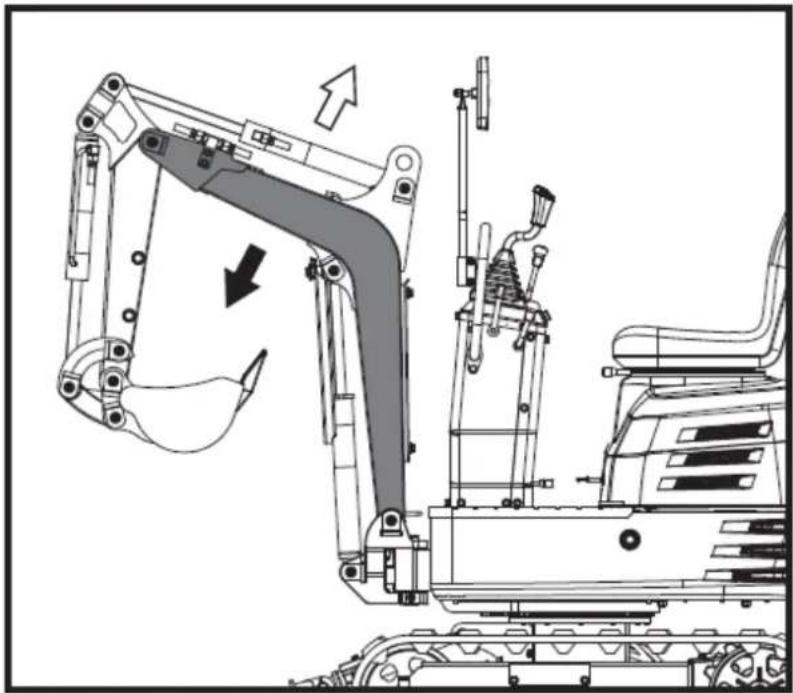
natural_image
Technical line drawing of an excavator assembly with directional arrows indicating motion (no text or symbols)▲ Importantante
natural_image
Technical diagram of a mechanical or electrical component with no visible text, numbers, or symbols.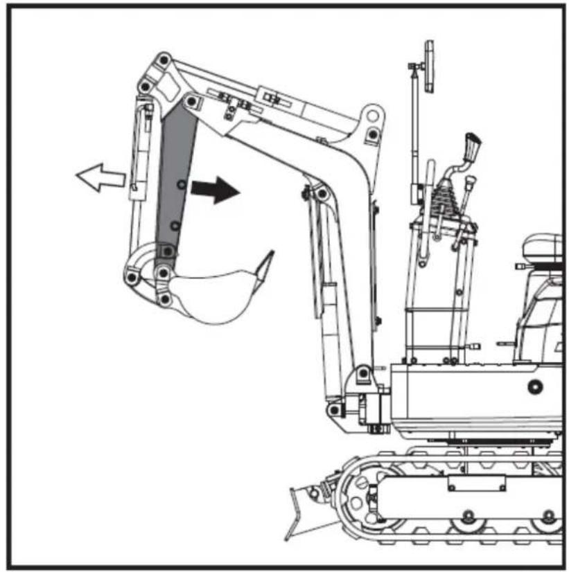
natural_image
Technical line drawing of an excavator and tracked vehicle (no text or symbols)5.4.8. Como funciona a concha
natural_image
Technical diagram of a piping system with valves and a valve mechanism (no text or labels)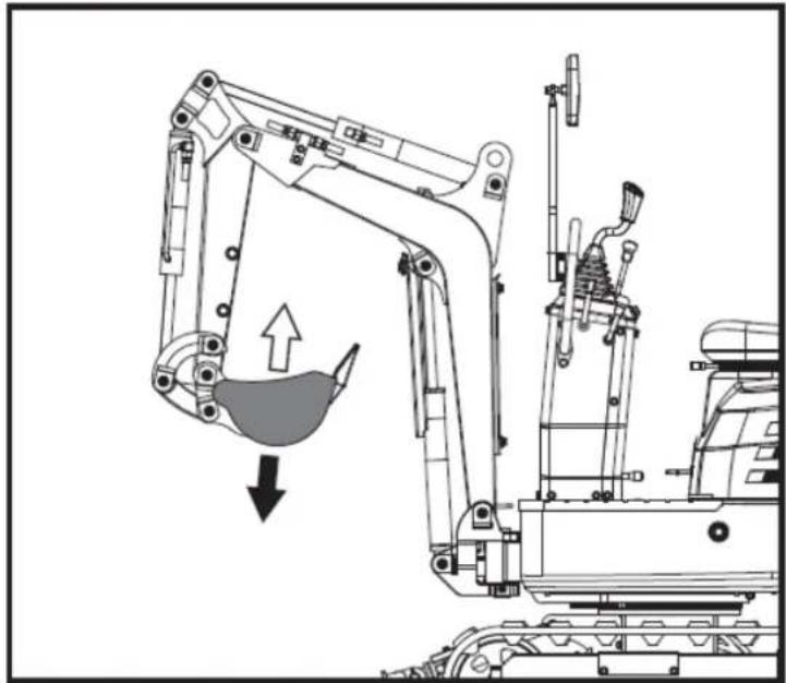
natural_image
Technical line drawing of an excavator with a downward load arrow, showing mechanical components and structural details (no text or symbols)natural_image
Technical diagram of a mechanical or industrial system with pipes and a central component, no visible text or symbols
natural_image
Technical line drawing of a mechanical assembly with internal components and directional arrows (no text or labels)natural_image
Technical line drawing of a mechanical device with no visible text or symbols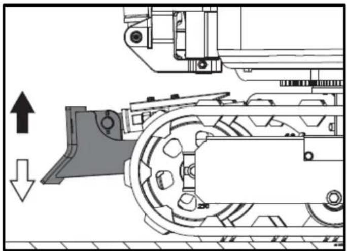
natural_image
Mechanical assembly diagram showing a conveyor belt system with directional arrows indicating motion (no text or labels)natural_image
Technical line drawing of a robotic excavator with labeled component A, showing mechanical assembly and ground-level reference (no text or symbols beyond label)natural_image
Technical line drawing of two excavators with directional arrows indicating movement (no text or symbols)▲ Importantante
natural_image
Line drawing of a bulldozer with a cross symbol crossed out, no text or symbols present5.5.2. Viradas
▲ Importante
natural_image
Technical diagram showing a mechanical assembly with an upward arrow and a side-view view of a tracked vehicle (no text or symbols present)A. Virar à esquerda B. Virar à esquerda

natural_image
Line drawing of an excavator on a construction ground (no text or symbols)natural_image
Technical line drawing of an excavator on a slope, showing mechanical components and a labeled section A (no text or symbols present)A. Cunha
natural_image
Line drawing of an excavator on a dump truck, no text or symbols presentPerigo
natural_image
Illustration of a truck with a worker kneeling beside it, showing structural damage or damage (no text or symbols)natural_image
Line drawing of a construction truck with an excavator on an inclined ramp (no text or symbols)natural_image
Cartoon illustration of a front-end loader dumping material into a pile of waste (no text or symbols)- Prender as correntes/correias.
natural_image
Technical line drawing of an excavator with labeled component A (no text or symbols beyond label)A. Algema
natural_image
Technical line drawing of a tracked vehicle with labeled component A (no text or symbols beyond label)A. Algema
PT

6. MANUTENÇÃO
natural_image
Technical line drawing of a mechanical assembly with labeled component A (no text or symbols beyond label)natural_image
Technical line drawing of a mechanical assembly with labeled component A (no text or symbols beyond label)A. Saída de ar
natural_image
Technical line drawing of an electric motor assembly with labeled components (no text or symbols present)natural_image
Technical line drawing of a tank interior showing engine, chassis, and structural components (no text or labels)natural_image
Technical line drawing of a mechanical assembly with labeled parts A and B (no readable text or symbols)natural_image
Technical line drawing of a tracked vehicle with visible tracks and structural components (no text or symbols)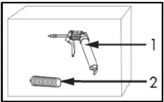
natural_image
Technical line drawing of a mechanical assembly with labeled component A (no text or symbols beyond label)A. Interruptor do fio de terra negativo (DESLIGADO)
natural_image
Technical line drawing of a tracked vehicle with labeled component 'A' (no text or symbols beyond label)natural_image
Silhouette of a human head with an eyepatch and motion arrows indicating speed or effort (no text or symbols)natural_image
Illustration of a hand holding a pen over a striped rectangular object (no text or symbols)▲ Importantante
natural_image
Technical line drawing of a vehicle engine bay with labeled component 'A' (no text or symbols beyond label)natural_image
Technical line drawing of a tracked vehicle with labeled components (no text or symbols present)natural_image
Technical line drawing of a tracked vehicle with labeled component A (no text or symbols beyond label)A. Filtro de retorno
B. Bocal de enchimento de óleo hidráulico
natural_image
Technical line drawing of a tracked vehicle with labeled component A (no text or symbols beyond label)A. Parafuso M20x120
Porca B. M20
natural_image
Technical line drawing of an excavator with tracked arm and base mount (no text or symbols)
A. União
Importante
natural_image
Technical line drawing of an automotive engine assembly with labeled components (A and B), showing internal components and wiring (no text or symbols beyond labels)
Esquema do sistema hidráulico
flowchart
graph TD
    A["100kV"] --> B["3.836"]
    B --> C["2x2.6mL/T"]
    C --> D["7.015"]
    C --> E["17.5MPa"]
    C --> F["17.5MPa"]
    C --> G["17.5MPa"]
    C --> H["17.5MPa"]
    C --> I["17.5MPa"]
    C --> J["17.5MPa"]
    C --> K["17.5MPa"]
    C --> L["17.5MPa"]
    C --> M["17.5MPa"]
    C --> N["17.5MPa"]
    C --> O["17.5MPa"]
    C --> P["17.5MPa"]
    C --> Q["17.5MPa"]
    C --> R["17.5MPa"]
    C --> S["17.5MPa"]
    C --> T["17.5MPa"]
    C --> U["17.5MPa"]
    C --> V["17.5MPa"]
    C --> W["17.5MPa"]
    C --> X["17.5MPa"]
    C --> Y["17.5MPa"]
    C --> Z["17.5MPa"]
    C --> AA["17.5MPa"]
    C --> AB["17.5MPa"]
    C --> AC["17.5MPa"]
    C --> AD["17.5MPa"]
    C --> AE["17.5MPa"]
    C --> AF["17.5MPa"]
    C --> AG["17.5MPa"]
    C --> AH["17.5MPa"]
    C --> AI["17.5MPa"]
    C --> AJ["17.5MPa"]
    C --> AK["17.5MPa"]
    C --> AL["17.5MPa"]
    C --> AM["17.5MPa"]
    C --> AN["17.5MPa"]
    C --> AO["17.5MPa"]
    C --> AP["17.5MPa"]
    C --> AQ["17.5MPa"]
    C --> AR["17.5MPa"]
    C --> AS["17.5MPa"]
    C --> AT["17.5MPa"]
    C --> AU["17.5MPa"]
    C --> AV["17.5MPa"]
    C --> AW["17.5MPa"]
    C --> AX["17.5MPa"]
    C --> AY["17.5MPa"]
    C --> AZ["17.5MPa"]
    C --> BA["17.5MPa"]
    C --> BB["17.5MPa"]
    C --> BC["17.5MPa"]
    C --> BD["17.5MPa"]
    C --> BE["17.5MPa"]
    C --> BF["17.5MPa"]
    C --> BG["17.5MPa"]
    C --> BH["17.5MPa"]
    C --> BI["17.5MPa"]
    C --> BJ["17.5MPa"]
    C --> BK["17.5MPa"]
    C --> BL["17.5MPa"]
    C --> BM["17.5MPa"]
    C --> BN["17.5MPa"]
    C --> BO["17.5MPa"]
    C --> BP["17.5MPa"]
    C --> BQ["17.5MPa"]
    C --> BR["17.5MPa"]
    C --> BS["17.5MPa"]
    C --> BT["17.5MPa"]
    C --> BU["17.5MPa"]
    C --> BV["17.5MPa"]
    C --> BW["17.5MPa"]
    C --> BX["17.5MPa"]
    C --> BY["17.5MPa"]
    C --> BZ["17.5MPa"]
    C --> CA["17.5MPa"]
    C --> CB["17.5MPa"]
    C --> CC["17.5MPa"]
    C --> CD["17.5MPa"]
    C --> CE["17.5MPa"]
    C --> CF["17.5MPa"]
    C --> CG["17.5MPa"]
    C --> CH["17.5MPa"]
    C --> CI["17.5MPa"]
    C --> CJ["17.5MPa"]
    C --> CK["17.5MPa"]
    C --> CR["17.5MPa"]
    C --> CS["17.5MPa"]
    C --> CT["17.5MPa"]
    C --> CU["17.5MPa"]
    C --> CV["17.5MPa"]
    C --> CW["17.5MPa"]
    C --> CX["17.5MPa"]
    C --> CY["17.5MPa"]
    C --> CZ["17.5MPa"]

7. ACESSÓRIOS OPCIONAIS
natural_image
Line drawing of an excavator with levers and bucket (no text or symbols)7.2. Ancinho
natural_image
Technical line drawing of an excavator with tracked blade and bucket (no text or symbols)natural_image
Technical line drawing of an excavator and tracked vehicle (no text or symbols)natural_image
Line drawing of an excavator with tracked base and bucket (no text or symbols)7.4. Garra
natural_image
Line drawing of an excavator with tracked base and mechanical components (no text or symbols)natural_image
Technical line drawing of an excavator with attached mechanical components (no text or symbols)natural_image
Technical line drawing of an excavator assembly (no text or symbols present)7.5. pá niveladora
natural_image
Line drawing of an excavator with tracked base and blade assembly (no text or symbols)natural_image
Technical line drawing of an excavator with levers and tracked components (no text or symbols)7.6. Deck
natural_image
Technical line drawing of an excavator with attached tracks and structural components (no text or symbols)natural_image
Line drawing of an excavator with tracked track and mechanical components (no text or symbols)natural_image
Technical line drawing of an excavator with tracked base and attached levers (no text or symbols)PT

12. CERTIFICADO CE
natural_image
Exterior view of a black and gray DNOVA EX6SOT excavator with tracked tracks (no visible text or symbols on the device body)FR
ANOVA®


flowchart
graph TD
    A["Camera"] --> B["Sensor"]
    B --> C["Lock Function"]
    C --> D["5 keyhole locked"]
    D --> E["Switch"]
    E --> F["Monitor"]
    F --> G["Switch"]
    G --> H["Switch"]
    H --> I["Switch"]
    I --> J["Switch"]
    J --> K["Switch"]
    K --> L["Switch"]
    L --> M["Switch"]
    M --> N["Switch"]
    N --> O["Switch"]
    O --> P["Switch"]
    P --> Q["Switch"]
    Q --> R["Switch"]
    R --> S["Switch"]
    S --> T["Switch"]
    T --> U["Switch"]
    U --> V["Switch"]
    V --> W["Switch"]
    W --> X["Switch"]
    X --> Y["Switch"]
    Y --> Z["Switch"]
natural_image
Three identical diagrams showing mechanical or electrical components with no visible text, numbers, or symbols.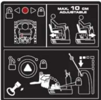
natural_image
Illustration of a magnifying glass examining a document with a hand holding it, symbolizing search or review (no text present)Tube manuel
flowchart
graph TD
    A["1: Control Panel"] --> B["2: Robot Arm"]
    B --> C["3: Control Panel"]
    C --> D["4: Robot Arm"]
    D --> E["5: Control Panel"]
    E --> F["6: Robot Arm"]
    F --> G["7: Control Panel"]
    G --> H["8: Robot Arm"]
    H --> I["9: Control Panel"]
    I --> J["10: Robot Arm"]
    J --> K["11: Control Panel"]
    K --> L["12: Robot Arm"]
    L --> M["13: Control Panel"]
    M --> N["14: Robot Arm"]
    N --> O["15: Control Panel"]
    O --> P["16: Robot Arm"]
    P --> Q["17: Control Panel"]
    Q --> R["18: Robot Arm"]
    R --> S["19: Control Panel"]
    S --> T["20: Robot Arm"]
natural_image
Line drawing of an excavator performing maintenance on power lines (no text or symbols)natural_image
Technical line drawing of an excavator on a construction site (no text or symbols)natural_image
Technical line drawing of a vehicle chassis with labeled sections A and B (no text or symbols on the diagram itself)natural_image
Technical line drawing of an excavator with attached equipment, shown in side profile (no text or symbols)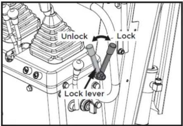
FR
natural_image
Line drawing of a construction truck with an excavator and bucket, parked near clouds (no text or symbols)1
2

3
4
5
6
7
8
9


10

flowchart
graph TD
    A["Robot"] --> B["Control Unit"]
    C["Robot"] --> D["Control Unit"]
    E["Robot"] --> F["Control Unit"]
    G["Robot"] --> H["Control Unit"]
    I["Robot"] --> J["Control Unit"]
    K["Robot"] --> L["Control Unit"]
    M["Robot"] --> N["Control Unit"]
    O["Robot"] --> P["Control Unit"]
    Q["Robot"] --> R["Control Unit"]
    S["Robot"] --> T["Control Unit"]
    U["Robot"] --> V["Control Unit"]
    W["Robot"] --> X["Control Unit"]
    Y["Robot"] --> Z["Control Unit"]
    AA["Robot"] --> AB["Control Unit"]
    AC["Robot"] --> AD["Control Unit"]
    AE["Robot"] --> AF["Control Unit"]
    AG["Robot"] --> AH["Control Unit"]
    AI["Robot"] --> AJ["Control Unit"]
    AK["Robot"] --> AL["Control Unit"]
    AM["Robot"] --> AN["Control Unit"]
    AO["Robot"] --> AP["Control Unit"]
    AQ["Robot"] --> AR["Control Unit"]
    AS["Robot"] --> AT["Control Unit"]
    AU["Robot"] --> AV["Control Unit"]
    AW["Robot"] --> AX["Control Unit"]
    AY["Robot"] --> AZ["Control Unit"]
    BA["Robot"] --> BB["Control Unit"]
    BC["Robot"] --> BD["Control Unit"]
    BE["Robot"] --> BF["Control Unit"]
    BG["Robot"] --> BH["Control Unit"]
    BI["Robot"] --> BJ["Control Unit"]
    BK["Robot"] --> BL["Control Unit"]
    BM["Robot"] --> BN["Control Unit"]
    BO["Robot"] --> BP["Control Unit"]
    BQ["Robot"] --> BR["Control Unit"]
    BS["Robot"] --> BT["Control Unit"]
    BU["Robot"] --> BV["Control Unit"]
    BW["Robot"] --> BX["Control Unit"]
    BY["Robot"] --> BZ["Control Unit"]
    CA["Robot"] --> CB["Control Unit"]
    CC["Robot"] --> CD["Control Unit"]
    CE["Robot"] --> CF["Control Unit"]
    DG["Robot"] --> DH["Control Unit"]
    DI["Robot"] --> DJ["Control Unit"]
    DK["Robot"] --> DL["Control Unit"]
    DM["Robot"] --> DE["Control Unit"]
    DF["Robot"] --> DG
    DG --> DG
    DG --> DG
    DG --> DG
    DG --> DG
    DG --> DG
    DG --> DG
    DG --> DG
    DG --> DG
    DG --> DG
    DG --> DG
    DG --> DG
    DG --> DG
    DG --> DG
    DG --> DG
    DG --> DG
    DG --> DG
    DG --> DG
    DG --> DG
    DG --> DG
    DG --> DG
    DN["Robot"] --> DN
    DN --> DN
    DN --> DN
    DN --> DN
    DN --> DN
    DN --> DN
    DN --> DN
    DN --> DN
    DN --> DN
    DN --> DN
    DN --> DN
    DN --> DN
    DN --> DN
    DN --> DN
    DN --> DN
    DN --> DN
    DN --> DN
    DN --> DN
    DN --> DN
    DN --> DN
    DN --> DN
    BN["Robot"] --> BO
    BN --> BC
    BN --> DA
    BN --> DW
    BN --> PX
    BN --> DY
    BN --> DY
    BN --> DY
    BN --> DY
    BN --> DY
    BN --> DY
    BN --> DY
    BN --> DY
    BN --> DY
    BN --> DY
    BN --> DY
    BN --> DY
    BN --> DY
    BN --> DY
    BN --> DY
    BN --> DY
    BN --> DY
11


12
13

17

14

18

natural_image
Three identical diagrams showing a spacecraft and a ground vehicle with red warning symbols, no text or labels present.15
16

4.2. Montage
natural_image
Technical line drawing of a vehicle seat assembly with an L-shaped chair and internal components (no text or symbols)5. INSTRUCTIONS D'UTILISATION
natural_image
Technical line drawing of a mechanical device with labeled component A (no text or symbols beyond label)natural_image
Technical line drawing of a mechanical device with labeled components (no readable text or symbols)natural_image
Technical line drawing of a mechanical device with labeled component A (no text or symbols beyond label)A. Compteur horaire
natural_image
Technical line drawing of a mechanical assembly with no visible text or symbolsnatural_image
Technical diagram of a piping system with valve and valve components (no text or labels)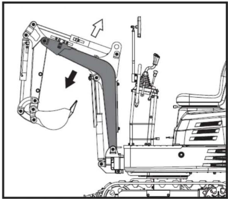
natural_image
Technical line drawing of an excavator assembly with no visible text or symbols▲ Important
natural_image
Technical diagram of a mechanical or electrical component with pipe connections and a highlighted section showing a downward arrow (no text or symbols present)
natural_image
Technical line drawing of an excavator and tracked vehicle (no text or symbols)natural_image
Technical diagram of a piping system with valves and valves, showing directional flow arrows (no text or labels)
natural_image
Technical line drawing of an excavator with load and component assembly (no text or symbols)natural_image
Technical diagram of a mechanical or industrial system with pipes and a central component, no visible text or symbols
natural_image
Technical line drawing of a mechanical assembly with no visible text or symbolsnatural_image
Technical line drawing of a mechanical device with no visible text or symbols
natural_image
Technical diagram of a mechanical assembly with directional arrows indicating motion (no text or symbols)natural_image
Technical line drawing of a tracked excavator with labeled component A, showing mechanical assembly and movement (no text or symbols beyond label)natural_image
Technical line drawing of two excavators with directional arrows indicating movement (no text or symbols)▲ Important
natural_image
Line drawing of a bulldozer with a cross symbol crossed out, no text or symbols present5.5.2. Tours
▲ Important
natural_image
Technical diagram showing a mechanical assembly with an arrow indicating rotational motion (no text or symbols present)FR
natural_image
Line drawing of an excavator on a construction ground (no text or symbols)5.5.5. Parking en pente
Avertissement
natural_image
Technical line drawing of an excavator on a sloped terrain, labeled with point A (no text or symbols beyond label)A. Coin
natural_image
Line drawing of an excavator on a dump truck, no text or symbols presentDanger
natural_image
Illustration of a worker pushing a dump truck with an upward arrow indicating load or damage (no text or symbols)FR
natural_image
Line drawing of a construction vehicle with an excavator on a sloped terrain (no text or symbols)natural_image
Cartoon illustration of a front-end loader dumping material into a pile, with no text or symbols present.natural_image
Technical line drawing of an excavator with labeled component A (no text or symbols beyond label)A. Manille
natural_image
Technical line drawing of a tracked vehicle with labeled component A (no text or symbols beyond label)A. Manille
FR

6. ENTRETIEN
natural_image
Technical line drawing of a mechanical assembly with labeled component A (no text or symbols beyond label)natural_image
Technical line drawing of a mechanical assembly with labeled component A (no text or symbols beyond label)A. Orifice de ventilation
natural_image
Technical line drawing of an electric motor assembly with labeled components (no text or symbols present)natural_image
Technical line drawing of a tank interior showing engine, chassis, and structural components (no text or labels)natural_image
Technical line drawing of a tracked vehicle with visible tracks and structural components (no text or symbols)
natural_image
Technical line drawing of a mechanical assembly with labeled component A (no text or symbols beyond label)natural_image
Technical line drawing of a tracked vehicle with labeled component 'A' (no text or symbols beyond label)natural_image
Silhouette of a human head with an eyepatch and motion arrows indicating sound or motion (no text or symbols)natural_image
Illustration of a hand using a tool to mark a grating or surface treatment (no text or symbols present)▲ Important
natural_image
Technical line drawing of a vehicle engine bay with labeled component 'A' (no text or symbols beyond label)natural_image
Technical line drawing of a tracked vehicle with labeled component 'A' (no text or symbols beyond label)natural_image
Technical line drawing of a tracked vehicle with labeled component A (no text or symbols beyond label)natural_image
Technical line drawing of a tracked vehicle with labeled component A (no text or symbols beyond label)A. Bouchon de vidange
A. Vis M20x120
Écrou B. M20
natural_image
Technical line drawing of an excavator with tracked arm and base mount (no text or symbols)
A. Union
▲ Important
natural_image
Technical line drawing of a vehicle engine compartment with labeled components (A and B), showing internal wiring and structural details without any readable text or symbols.
natural_image
Line drawing of a tracked excavator with levers and bucket (no text or symbols)7.2. Râteau
natural_image
Line drawing of an excavator with tracked blade and bucket (no text or symbols)natural_image
Technical line drawing of an excavator and tracked vehicle (no text or symbols)natural_image
Line drawing of an excavator with tracked base and mechanical arms (no text or symbols)7.4. Griffe
natural_image
Line drawing of an excavator with tracked base and mechanical components (no text or symbols)7.4.1. Installation de griffes
natural_image
Technical line drawing of an excavator with tracked base and control panel (no text or symbols)natural_image
Technical line drawing of an excavator assembly (no text or symbols present)natural_image
Line drawing of an excavator with tracked base and bucket (no text or symbols)natural_image
Technical line drawing of an excavator with tracked base and bucket, no text or symbols present7.6. Pont
natural_image
Technical line drawing of an excavator with tracked base and attached bucket (no text or symbols)natural_image
Line drawing of an excavator with tracked base and control panel (no text or symbols)natural_image
Technical line drawing of an excavator with tracked base and attached levers (no text or symbols)8. DÉPANNAGE
Avertissement
FR

SOCIÉTÉ DE DISTRIBUTION
MILLASUR, SLU
DÉCLARATION DE CONFORMITÉ CE
Directive 2006/42/CE
2000/14/CE
2005/88/CE
natural_image
Exterior view of a black and gray ANOVA EHX50T excavator (no signage or text on body)IT
ANOVA®
flowchart
graph TD
    A["Hand with lock"] --> B["Lock Icon"]
    B --> C["Lock Padlock Icon"]
    C --> D["Lock Icon"]
    D --> E["Lock Padlock Icon"]

natural_image
Three identical diagrams of robotic arm systems with no text or symbols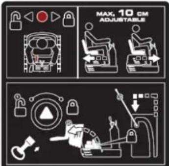
natural_image
Illustration of a hand holding a smartphone with magnifying glass examining a device (no text or symbols)Tubo manuale

flowchart
graph TD
    A["1: Robot Arm"] --> B["2: Robot Arm"]
    B --> C["3: Control Panel"]
    C --> D["4: Robot Arm"]
    D --> E["5: Control Panel"]
    E --> F["6: Robot Arm"]
    F --> G["7: Control Panel"]
    G --> H["8: Robot Arm"]
    H --> I["9: Control Panel"]
    I --> J["10: Robot Arm"]
    J --> K["11: Control Panel"]
    K --> L["12: Robot Arm"]
    L --> M["13: Control Panel"]
    M --> N["14: Robot Arm"]
    N --> O["15: Control Panel"]
    O --> P["16: Robot Arm"]
    P --> Q["17: Control Panel"]
    Q --> R["18: Robot Arm"]
    R --> S["19: Control Panel"]
    S --> T["20: Robot Arm"]
natural_image
Line drawing of an excavator on a utility pole, no text or symbols presentnatural_image
Technical line drawing of an excavator on a construction site (no text or symbols)natural_image
Technical line drawing of a vehicle chassis with labeled sections A and B (no text or symbols beyond labels)A. Fronte B. Posteriore
natural_image
Technical line drawing of an excavator with attached equipment (no text or symbols)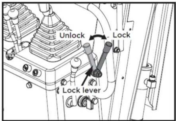
natural_image
Line drawing of a construction vehicle with an excavator and pile debris (no text or symbols)1

2
3


4

5

6

7

8

9


10
flowchart
graph TD
    A["Robot Arm"] --> B["Control Unit"]
    C["Engine Mount"] --> D["Control Unit"]
    E["Drain Arm"] --> F["Control Unit"]
    G["Tool Mount"] --> H["Control Unit"]
    I["Pressure Gauge"] --> J["Control Unit"]
    K["Sensor"] --> L["Control Unit"]
    M["Sensor"] --> N["Control Unit"]
    O["Sensor"] --> P["Control Unit"]
    Q["Sensor"] --> R["Control Unit"]
    S["Sensor"] --> T["Control Unit"]
    U["Sensor"] --> V["Control Unit"]
    W["Sensor"] --> X["Control Unit"]
    Y["Sensor"] --> Z["Control Unit"]
IT
11
12
13
17
flowchart
graph TD
    A["Robot Arm"] --> B["Control Unit"]
    C["Robot Arm"] --> D["Control Unit"]
    E["Lock"] --> F["Lock"]
    G["Lock"] --> H["Lock"]
    I["5 joystick locked"] --> J["Control Unit"]
    K["5 joystick locked"] --> L["Control Unit"]
14

18
15
16

4.2. Montaggio
natural_image
Technical line drawing of a vehicle's seat assembly and maintenance components (no text or symbols)5. ISTRUZIONI PER L'USO
natural_image
Technical line drawing of a mechanical device with labeled component A (no text or symbols beyond label)natural_image
Technical line drawing of a mechanical device with labeled components (no readable text or symbols)natural_image
Technical line drawing of a mechanical device with labeled component A (no text or symbols beyond label)A. Contaore
natural_image
Technical line drawing of a mechanical assembly with no visible text or symbolsnatural_image
Technical diagram of a piping system with valve and valve components (no text or labels)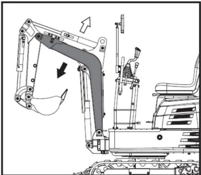
natural_image
Technical line drawing of an excavator assembly with no visible text or symbols▲Importante
natural_image
Technical diagram of a mechanical or electrical component with pipe connections and a highlighted section showing a downward arrow (no text or symbols present)
natural_image
Technical line drawing of a tracked excavator with attached mechanical components (no text or symbols)natural_image
Technical diagram of a piping system with valves and valves, showing internal components and directional arrows (no text or labels)
natural_image
Technical line drawing of an excavator with a downward load arrow, showing mechanical components without any text or symbols.natural_image
Technical diagram of a mechanical or industrial system with pipes and a central component, no visible text or symbols
natural_image
Technical line drawing of a mechanical assembly with no visible text or symbolsnatural_image
Technical line drawing of a mechanical device with no visible text or symbols
natural_image
Technical diagram of a mechanical assembly with directional arrows indicating motion (no text or symbols)natural_image
Technical line drawing of a robotic excavator with labeled component A, showing mechanical assembly and ground-level reference (no text or symbols beyond label)natural_image
Technical line drawing of two excavators on a construction ground, showing different mechanical configurations (no text or symbols present)▲ Importantante
natural_image
Line drawing of a bulldozer with a cross symbol crossed out, no text or symbols present5.5.2. giri
▲ Importantante
natural_image
Technical diagram showing a mechanical assembly with an upward arrow and a side-view view of a tracked vehicle (no text or symbols present)natural_image
Line drawing of an excavator on a construction ground (no text or symbols)natural_image
Technical line drawing of an excavator on a slope, labeled with point A (no text or symbols beyond label)A. Cuneo
natural_image
Line drawing of a construction vehicle with an excavator on an inclined plane (no text or symbols)Pericolo
natural_image
Illustration of a truck with a worker kneeling beside it, showing a pile of sand or material on the ground (no text or symbols)natural_image
Line drawing of a flatbed dump truck with an excavator on an inclined ramp (no text or symbols)natural_image
Cartoon illustration of a front-end loader dumping material into a pile, with no text or symbols present.natural_image
Technical line drawing of an excavator with labeled component A (no text or symbols beyond label)A. Catena
natural_image
Technical line drawing of a tracked vehicle with conveyor belt and mechanical components (no text or symbols)A. Catena
IT
6. MANUTENZIONE
natural_image
Technical line drawing of a mechanical assembly with labeled component A (no text or symbols beyond label)natural_image
Technical line drawing of a mechanical assembly with labeled component A (no text or symbols beyond label)A. Presa d'aria
natural_image
Technical line drawing of an electric motor assembly with labeled components (no text or symbols present)natural_image
Technical line drawing of a tank interior showing engine, chassis, and structural components (no text or labels)natural_image
Technical line drawing of a tracked vehicle with visible tracks and structural components (no text or symbols)
natural_image
Technical line drawing of a mechanical assembly with labeled component A (no text or symbols beyond label)natural_image
Technical line drawing of a tracked vehicle with labeled component A (no text or symbols beyond label)natural_image
Silhouette of a human head with an eyepatch and motion arrows indicating speed or pressure (no text or symbols)natural_image
Line drawing of a hand holding a pen above a rectangular object with diagonal stripes (no text or symbols)▲ Importantante
natural_image
Technical line drawing of a vehicle engine bay with labeled components (no text or symbols beyond label)natural_image
Technical line drawing of a tracked vehicle with labeled component A (no text or symbols beyond label)natural_image
Technical line drawing of a tracked robotic vehicle with labeled component A (no text or symbols beyond label)natural_image
Technical line drawing of a tracked vehicle chassis with labeled component A (no text or symbols beyond label)A. Tappo di scarico
natural_image
Technical line drawing of an excavator with attached platform and base (no text or symbols)
A. Unione
▲ Importantante
natural_image
Technical line drawing of a mechanical assembly with labeled components (A and B), no readable text or symbols present.
natural_image
Technical line drawing of a tracked excavator with levers and bucket (no text or symbols)7.2. Rastrello
natural_image
Technical line drawing of an excavator with tracked blade and bucket (no text or symbols)natural_image
Technical line drawing of an excavator and tracked vehicle (no text or symbols)natural_image
Line drawing of an excavator with tracked base and bucket assembly (no text or symbols)7.4. Artiglio
natural_image
Line drawing of an excavator with tracked base and mechanical components (no text or symbols)natural_image
Line drawing of an excavator with attached mechanical components (no text or symbols)natural_image
Technical line drawing of an excavator assembly (no text or symbols present)7.5. Paletta livellatrice
natural_image
Line drawing of an excavator with tracked track and blade assembly (no text or symbols)natural_image
Technical line drawing of an excavator with tracked base and bucket, no text or symbols present7.6. Ponte
natural_image
Technical line drawing of an excavator with attached tracks and levers (no text or symbols)natural_image
Line drawing of an excavator with tracked track and mechanical components (no text or symbols)natural_image
Technical line drawing of an excavator with tracked base and attached levers (no text or symbols)8. RISOLUZIONE DEI PROBLEMI
Avvertimento
IT
Instructions and user manual
natural_image
Exterior view of a black and gray ANOVA EHX50T excavator (no signage or text on body)EN
ANOVA®
Anova We would like to congratulate you on choosing one of our products and guarantee the assistance and cooperation that has always distinguished our brand over time.
This machine is designed to last for many years and to be of great use if used according to the instructions in the user manual. We therefore recommend that you carefully read this instruction manual and follow all our recommendations.
For more information or questions, you can contact us through our web support at www.anova.es.
INFORMATION ABOUT THIS MANUAL
Pay attention to the information provided in this manual and on the appliance for your safety and the safety of others.
- This manual contains instructions for use and maintenance.
- Take this manual with you when you go to work with the machine.
- The content is correct at the time of printing.
- We reserve the right to make changes at any time without affecting our legal responsibilities.
- This manual is considered an integral part of the product and must remain with it in case of loan or resale.
- Request a new manual from your distributor if it is lost or damaged.
READ THIS MANUAL CAREFULLY BEFORE USING THE MACHINE

To ensure your machine delivers the best results, carefully read the usage and safety guidelines before using it.
OTHER WARNINGS:
Improper use could cause damage to the machine or other objects.
Adapting the machine to new technical requirements could cause differences between the content of this manual and the product purchased.
Read and follow all instructions in this manual. Failure to follow these instructions could result in serious personal injury.
INDEX
1. SAFETY INSTRUCTIONS
2. PRODUCT DESCRIPTION
2.1. Machine parts
2.2. Instrument panel and control elements
23. Main dimensions
3. TECHNICAL SPECIFICATIONS
4. TECHNICAL ASSEMBLY INSTRUCTIONS
4.1. Unpacking
4.2. Mounting
5. OPERATING INSTRUCTIONS
5.1. Before operation
5.2. Engine operation
5.3. Engine stop
5.4. Operating instructions
5.5. Driving
5.6. Important information about the operation of the excavator
5.7. Transporting the excavator on a truck
5.8. Excavator lift
6. MAINTENANCE
6.1. Opening and closing of pieces
6.2. Daily checks
6.3. Periodic inspections and maintenance work
6.4. Other adjustments and replacements
6.5. Long-term storage
6.6. Periodic replacement of important components
6.7. Recommended oils
6.8. Lifting capacity
7. OPTIONAL ACCESSORIES
8. TROUBLESHOOTING
9. WARRANTY
10.ENVIRONMENT
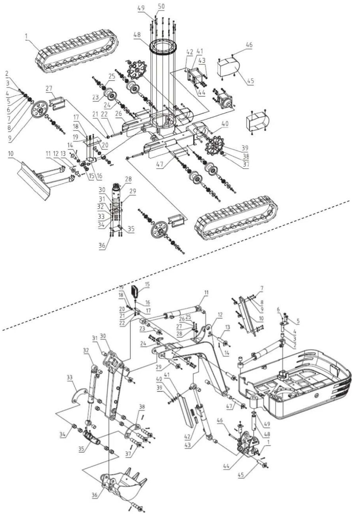
11. PARTS BREAKDOWN
12.CE CERTIFICATE
1. SAFETY INSTRUCTIONS
1.1. Safety instructions
▲ Important
Before operating this product, please read and follow the instructions below. To prevent injury to yourself and others, you should also follow local safety regulations.
Keep these instructions for future reference. This manual contains safety information to inform you about the hazards and risks associated with the product and how to prevent them. It also contains important instructions that must be followed during product setup, operation, and maintenance.
It is important that you read and understand these instructions before attempting to start or operate this equipment. Make sure you are fully familiar with the controls and the correct use of the product. Know how to quickly stop the unit and turn off the controls.
Throughout this manual, you will find notices that provide safety instructions and information about hazards that could cause personal injury and/or property damage. These include a warning icon to indicate the likelihood and potential severity of injury.
- Danger/Warning: Indicates a hazard that, if not avoided, could result in serious injury.
- Important/Caution: Indicates a hazard which, if not avoided, could result in minor or moderate injury.
- Note/Notice: Indicates information considered important but not related to hazards.
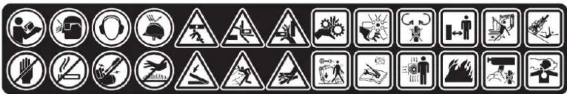
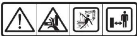
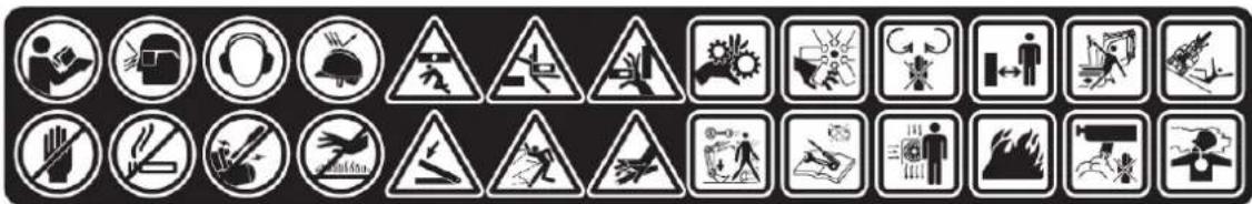
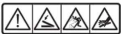
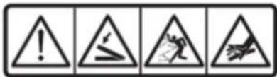
1.2. Safety symbols
The following safety symbols are crucial for using this product. Before using it, learn their meaning.
Caution
If the safety stickers on the machine become worn or damaged and illegible, they must be replaced. It is the user's/operator's responsibility to keep these stickers in good condition.
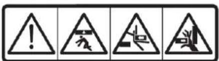
 | This is the safety alert symbol. When you see this symbol on your machine or in this manual, be alert to the possibility of personal injury. Follow the precautions and safe operating practices highlighted by this symbol. |
 | Read these instructions carefully. |
 | Use eye protection. |
 | Use hearing protection. |
 | Wear a safety helmet. |
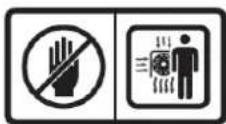
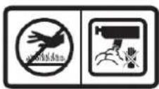
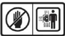
 | Do not touch |
 | No smoking, it may cause sparks or flames. |
 | Do not start the engine if the engine is not in good condition. |
 | Do not touch parts that are hot from operation. You could suffer serious burns. |
 | Stay away from this area to avoid serious injury or death. |
 | |
 | |
 | Be careful with your hands. |
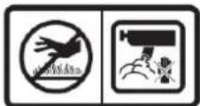
 | Please note that objects may be thrown during use. |
 | Do not use your hands to check for leaks. |
 | Keep away from rotating parts. |
 | Stay away from the fan. |
 | Keep your hands away from moving parts. Moving parts can crush or cut you. |
 | Keep people away from you. |
 | Pay attention to safety when working in front of the machine. |
 | Danger of rollover. |
 | When leaving the excavator, place the shovel close to the ground and remove the key. |
 | Turn off the engine, disconnect the spark plug wire, and ensure all moving parts have stopped before cleaning, repairing, or inspecting the unit. |
 | Be careful with overheating of ventilation systems |
 | Gasoline and its vapors are extremely flammable and explosive. |


Do not touch hot parts, such as the exhaust, etc.
Exhaust fumes are dangerous because they contain carbon monoxide. Remaining in that environment can cause serious or fatal injuries.
3-point lift
"Battery charging" alarm indicator
Ground wire disconnect switch (negative switch)
Secure the excavator
Fat
Hydraulic oil
Cooling fans
Lights
Horn button
Horn position
Hours
Power indicator
flowchart
graph TD
    A["Lock Icon"] --> B["Lock Icon"]
    B --> C["Lock Icon"]
    C --> D["Lock Icon"]
    D --> E["Lock Icon"]
    E --> F["Lock Icon"]
    style A fill:#f9f,stroke:#333
    style B fill:#ccf,stroke:#333
    style C fill:#cfc,stroke:#333
    style D fill:#fcc,stroke:#333
    style E fill:#cff,stroke:#333

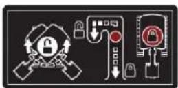
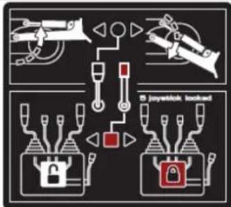
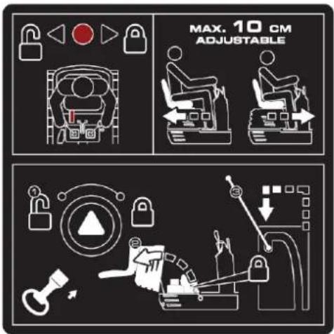
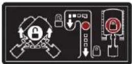
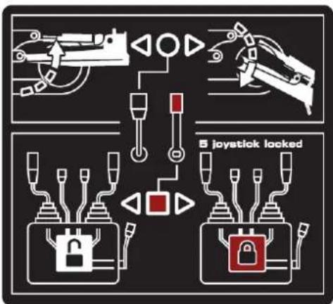
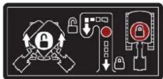
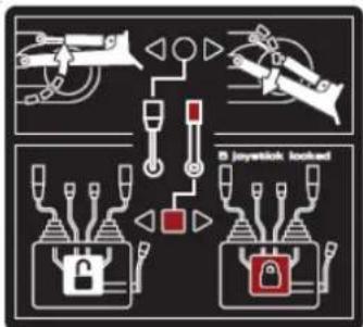
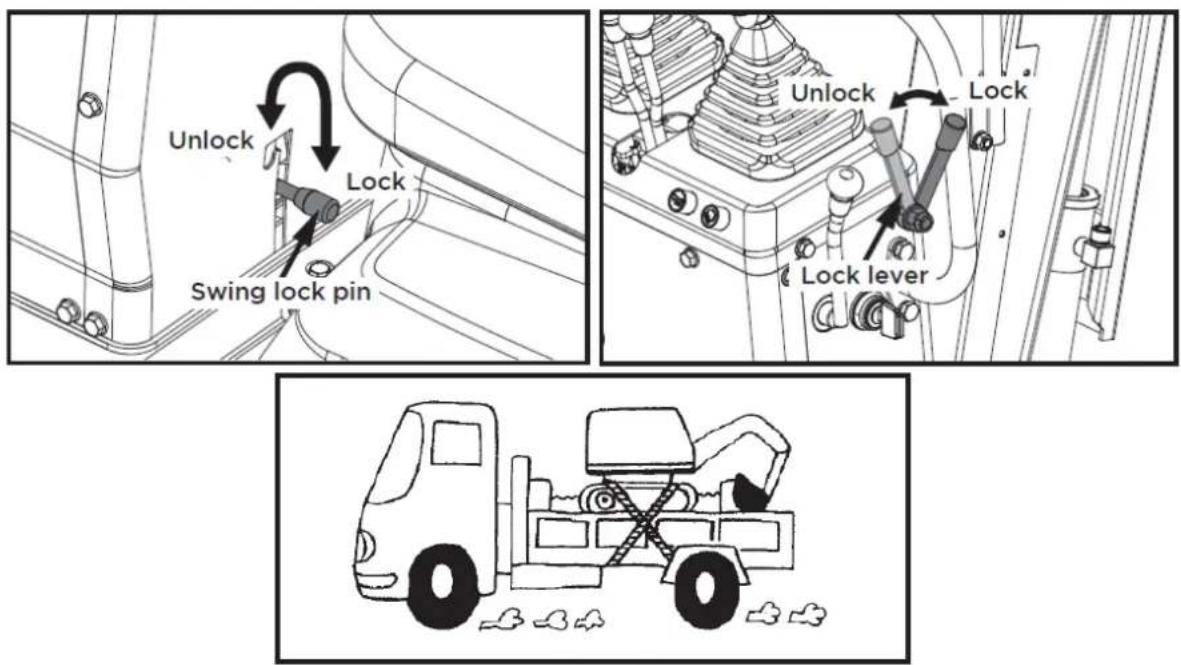
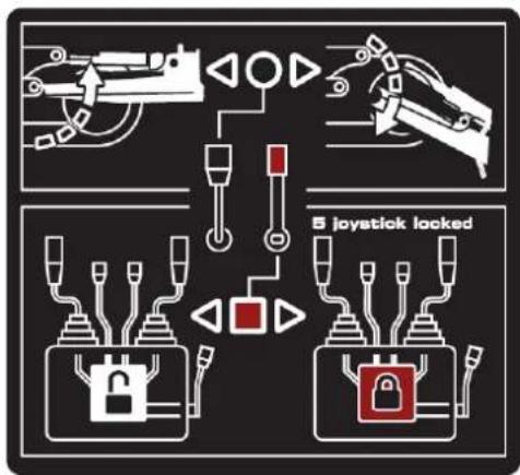
Instruct the user to lock or unlock the swing frame using the swing lock pin.
Always check the hydraulic oil level before using the machine.


flowchart
graph TD
    A["Lock"] --> B["Switch"]
    C["Lock"] --> D["Switch"]
    E["Gear"] --> F["Load"]
    G["Jet"] --> H["Load"]
    I["Jet"] --> J["Load"]
    K["Jet"] --> L["Load"]
    M["Jet"] --> N["Load"]
    O["Jet"] --> P["Load"]
    Q["Jet"] --> R["Load"]
    S["Jet"] --> T["Load"]
    U["Jet"] --> V["Load"]
    W["Jet"] --> X["Load"]
    Y["Jet"] --> Z["Load"]
    AA["Jet"] --> AB["Load"]
    AC["Jet"] --> AD["Load"]
    AE["Jet"] --> AF["Load"]
    AG["Jet"] --> AH["Load"]
    AI["Jet"] --> AJ["Load"]
    AK["Jet"] --> AL["Load"]
    AM["Jet"] --> AN["Load"]
    AO["Jet"] --> AP["Load"]
    AQ["Jet"] --> AR["Load"]
    AS["Jet"] --> AT["Load"]
    AU["Jet"] --> AV["Load"]
    AW["Jet"] --> AX["Load"]
    AY["Lock"] --> Z
    AZ["Lock"] --> AA
    BA["Lock"] --> AB
    BB["Lock"] --> AC
    BC["Lock"] --> AD
    BD["Lock"] --> AE
    BF["Lock"] --> AG
    BG["Lock"] --> AH
    BH["Lock"] --> AI
    BI["Lock"] --> AJ
    BJ["Lock"] --> AK
    BK["Lock"] --> AA
    BL["Lock"] --> AB
    BM["Lock"] --> AC
    BN["Lock"] --> AD
    BO["Lock"] --> AE
    BP["Lock"] --> AA
    BQ["Lock"] --> AB
    CA["Lock"] --> AC
    CB["Lock"] --> AD
    CC["Lock"] --> AE
    CD["Lock"] --> AF
    CE["Lock"] --> AG
    CF["Lock"] --> AH
    CG["Lock"] --> AI
    CH["Lock"] --> AJ
    CI["Lock"] --> AK
    CJ["Lock"] --> AL
    CK["Lock"] --> AL
natural_image
Three identical diagrams showing mechanical or robotic components with no visible text, numbers, or symbols.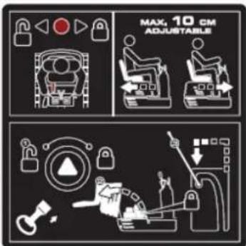
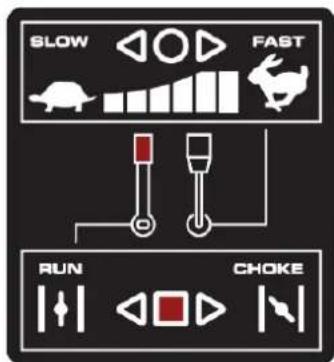
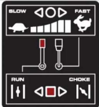
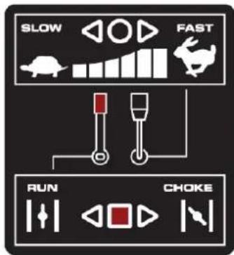
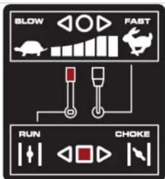
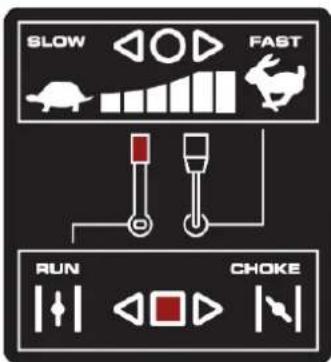
Throttle control The throttle control regulates the engine speed. The throttle control moves between the slow and fast positions.
12V, 15A power outlet
MOTOR ON/OFF/START SWITCH
The engine switch has three positions. OFF: the engine does not start or run. ON: the engine runs. Start: the engine starts.
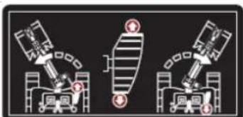
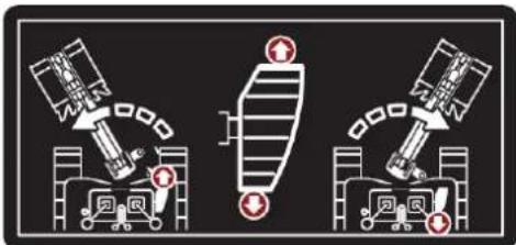
Pull back the black control lever to raise the blade. Push the lever forward to lower the blade.
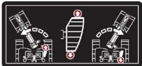
Press the front of the pedal to rotate the arm to the left. Press the back of the pedal to rotate the arm to the right.
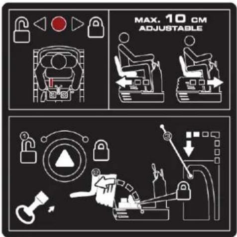
Hold the lever to the right to unlock the seat, and then make the adjustment.

natural_image
Illustration of a magnifying glass examining a document with a hand holding it, symbolizing search or review (no text present)
Manual tube
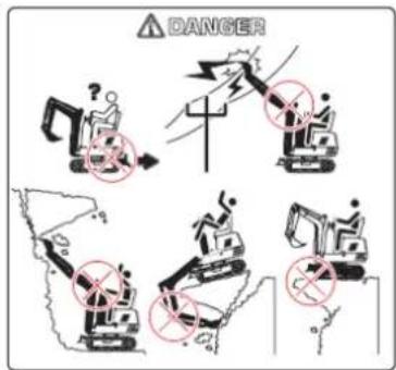
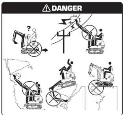
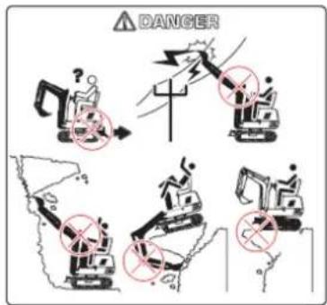
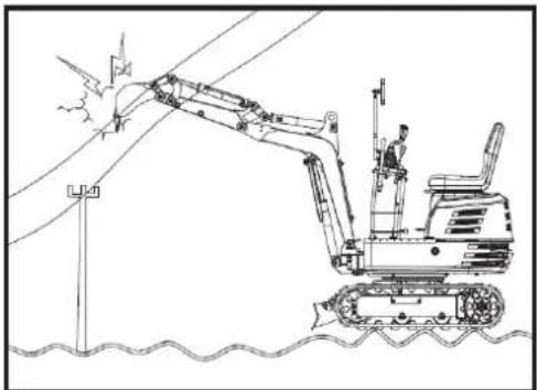
Avoid workplace hazards. Avoid contact with gas lines, underground cables, and water pipes. Call utility line locating services to identify all underground utilities before excavating. Properly prepare the work area. Avoid working near structures or objects that could fall on the machine. Remove debris that could move unexpectedly if stepped on. Avoid contact of the boom or arm with overhead obstacles or power lines. Never bring any part of the machine or load closer than 3 m (10 ft) plus twice the length of the line insulation to overhead wires.
Keep bystanders clear at all times. Keep bystanders away from raised booms, attachments, and unsupported loads. Avoid swinging or raising booms, attachments, or loads above or near personnel. Use barricades or a signal person to keep vehicles and pedestrians clear. Use a signal person if moving the machine in congested areas or where visibility is limited. Keep the signal person in sight at all times. Coordinate hand signals before starting the machine. Operate only on a solid base strong enough to support the machine. When working near an excavation, position travel motors away from the hole. Reduce machine speed when using the tool on or near the ground where hidden obstacles may be present (e.g., during snow removal or clearing mud, dirt, etc.).
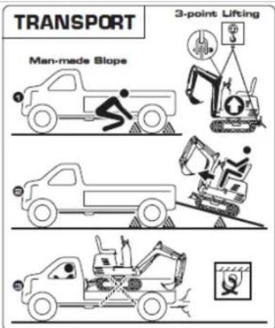
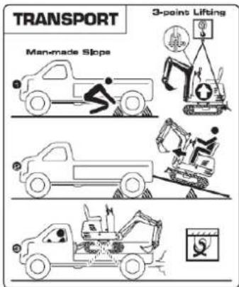
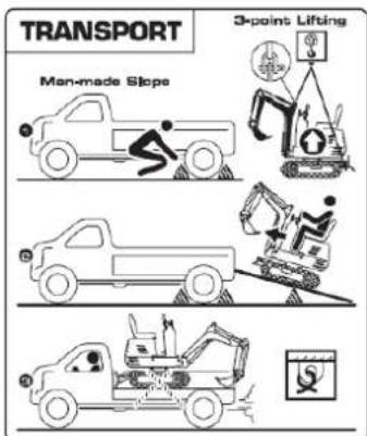
Use a 3-point lift system or ramp to load or unload the excavator.
Warning
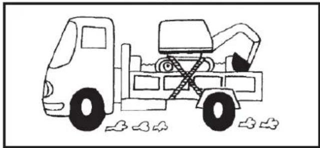
- Apply the truck's parking brakes and block the drive wheels on both sides.
- Use blocks or struts under the ramps and truck bed.
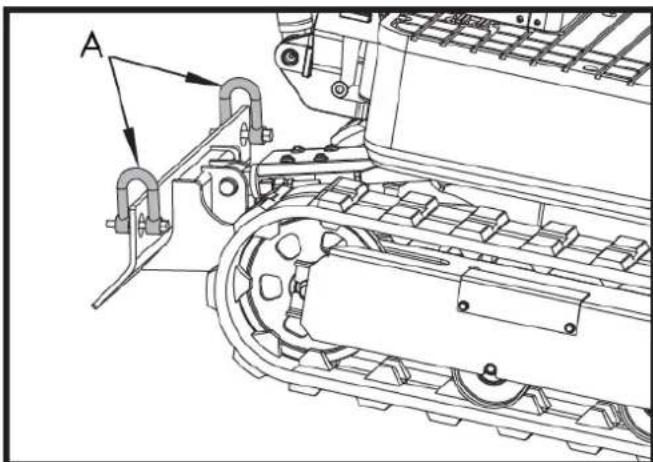
- Lock the tracks and tie down the excavator.
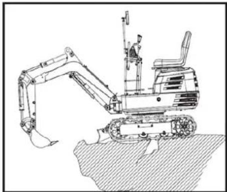
- To prevent personal injury or death: After loading the machine onto the truck, turn the upper body towards the rear of the truck and lock the rotating frame with the rotating locking pin.
Lower the bucket and shovel onto the truck bed, then lock the boom with the lever before getting out. Operating the machine while on the ground is prohibited.
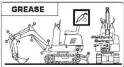
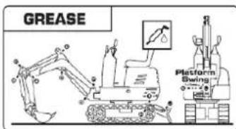
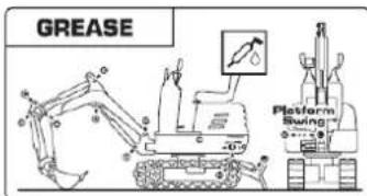
Grease the excavator periodically.
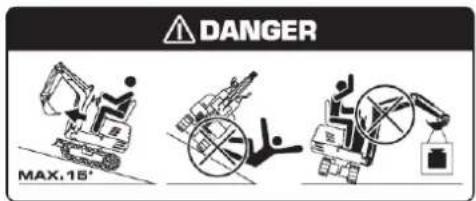
DANGER
Prevent the machine from tipping over
- Do not jump if the machine tips over. It is unlikely you will be able to jump in time and the machine could crush you.
- Load and unload trucks or trailers carefully. Ensure the truck is wide enough and on a firm, level surface. Use loading ramps and secure them properly to the truck bed. Avoid trucks with steel platforms, as tracks slip more easily on steel.
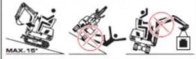
- Use caution on slopes. Exercise extreme caution on soft, rocky, or icy terrain. The machine may slip sideways in these conditions. When going up or down slopes, keep the bucket on the uphill side and just above ground level.
- Be careful with heavy loads. Using oversized buckets or lifting heavy objects reduces the machine's stability. Spreading a heavy load or balancing it on the side of the chassis can cause the machine to tip over.
- Make sure you have a solid base. Be very careful when operating near slopes or excavations that could collapse and cause the machine to tip over or fall.
flowchart
graph TD
    A["1: Control Panel"] --> B["2: Robot Arm"]
    B --> C["3: Control Panel"]
    C --> D["4: Robot Arm"]
    D --> E["5: Control Panel"]
    E --> F["6: Robot Arm"]
    F --> G["7: Control Panel"]
    G --> H["8: Robot Arm"]
    H --> I["9: Control Panel"]
    I --> J["10: Robot Arm"]
    J --> K["11: Control Panel"]
    K --> L["12: Robot Arm"]
    L --> M["13: Control Panel"]
    M --> N["14: Robot Arm"]
    N --> O["15: Control Panel"]
    O --> P["16: Robot Arm"]
    P --> Q["17: Control Panel"]
    Q --> R["18: Robot Arm"]
    R --> S["19: Control Panel"]
    S --> T["20: Robot Arm"]
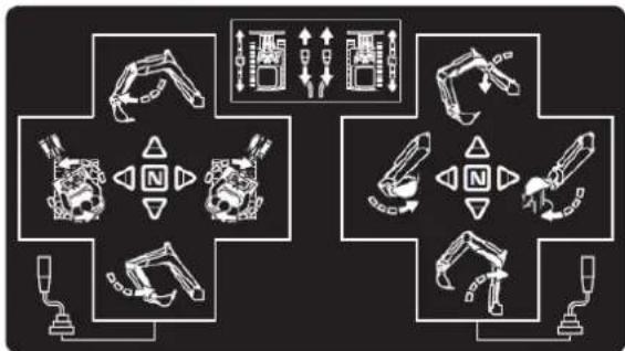
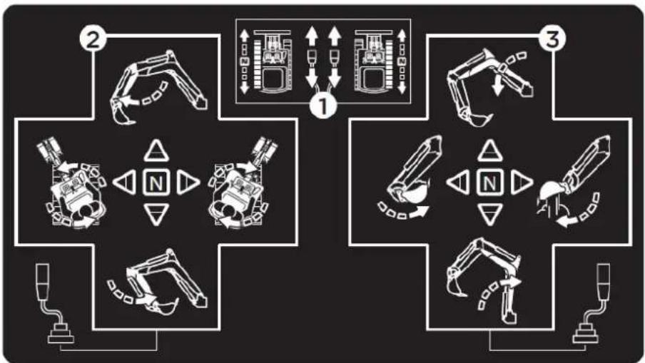
- Pushing both drive levers forward moves the excavator forward, and vice versa. The front of the excavator is the direction the bucket is facing. Operate only one side drive lever to change direction when the excavator is stationary or moving; operate the left and right drive levers in opposite directions to turn left and right.
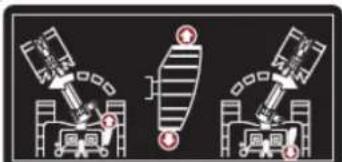
- Operation of the arm and rotation of the unit.
- How the pen and spoon work.
1.3. Safety instructions
Warning
Read and follow all safety rules and instructions in this manual before attempting to use this machine. Failure to follow these instructions may result in personal injury.
The best insurance against accidents is to comply with safety regulations.
All users, regardless of experience, must carefully read and understand this section and the sections on implements and accessories before operating the excavator. The owner is obligated to fully inform operators about these instructions. Keep this manual in the toolbox.
1.3.1. Before the operation
-
Familiarize yourself with the excavator and know its limitations. Carefully read this operator's manual before starting the excavator.
-
Respect the machine's hazard, warning, and caution labels.
-
Track gauge: 690mm. Operate on the correct track.
-
Do not operate the excavator under the influence of alcohol, medication, or other substances. Fatigue is also dangerous.
-
Carefully check the surroundings before using the excavator or when attaching accessories.
a. The excavator is not designed for use in contaminated environments.
b. Neither the excavator as a whole nor its internal components are designed for use in potentially explosive atmospheres.
c. Pay attention to the overhead clearance from electrical cables.
natural_image
Line drawing of an excavator machining a power line with a worker on the lift (no text or symbols)d. Check for buried pipes and cables.
e. Check for hidden holes, obstacles, soft ground, and protrusions.
natural_image
Technical line drawing of an excavator on a construction site (no text or symbols)f. During the use of the excavator, do not allow people inside the work area.
-
Do not allow other people to use the machine without first informing them about the exact operation and working instructions, and make sure that they have read and understood the operator's manual.
-
Do not wear loose, torn, or oversized clothing when operating an excavator. Clothing can become caught in rotating parts or control elements, which can lead to accidents or injuries. Wear appropriate safety clothing, such as a hard hat, safety shoes, eye protection, hearing protection, work gloves, etc., as required and as prescribed by laws or regulations.
-
Do not allow passengers to climb onto any part of the excavator seat while it is in operation.
-
Check that the mechanical parts are properly adjusted and show no signs of wear. Replace any worn or damaged parts immediately. Regularly check that the nuts and bolts are tight.
-
Keep the excavator clean. Dirt, grease, dust, and grass can ignite and cause accidents or injuries.
- Use only authorized accessories.
- Before starting the excavator, make sure it has been refueled, lubricated, greased and all other maintenance tasks have been carried out.
- Do not modify the excavator, as this could lead to unforeseen safety problems.
1.3.2. Excavator start-up
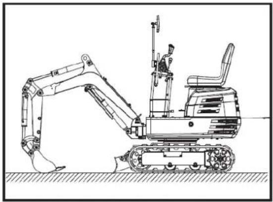
- Get on and off the machine safely. Always face the machine. Always use the available handrails and steps and maintain your balance. Do not hold any of the control levers or switches. Do not jump on or off the machine, whether it is stationary or moving.
- Start and operate the excavator only from the operator's seat. The operator must not lean out of the seat when the engine is running.
- Before starting the engine, make sure all control levers are in the neutral position.
- Do not start the engine by bypassing the starter motor connections. Do not attempt to circumvent the use of the starter switch, as the engine could start suddenly and the excavator could move.
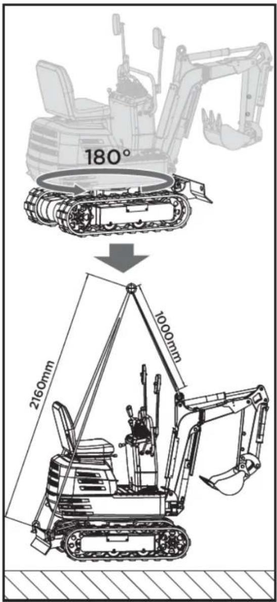
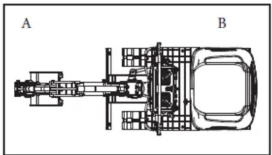
- Make sure the bucket is at the front (the bucket must be raised). If the swing frame has been rotated 180^ , meaning the bucket is, from the operator's perspective, "behind," then the direction of travel is opposite to the direction of the levers' movement (when the lever is moved forward, the excavator, from the operator's perspective, will move backward).
natural_image
Technical line drawing of a vehicle chassis with labeled sections A and B (no text or symbols on the diagram itself)A. Front B. Rear
- Do not start the engine in enclosed or poorly ventilated rooms. Carbon monoxide is colorless, odorless, and deadly.
- Keep all safety equipment and covers in place. Replace any damaged or missing safety devices.
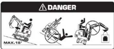
- Rollover precautions. To ensure safe operation, stay clear of steep slopes and embankments. Do not swing the bucket downwards. Lower the bucket during digging. Keep the bucket as low as possible while driving uphill. Turn slowly on slopes. Do not keep the excavator near the edges of trenches and embankments, as the ground may shift due to the excavator's weight.
- Pay attention at all times to the direction the excavator is moving. Be alert for obstacles.
- Maintain a safe distance from the edges of ditches and slopes.
Note: Child safety. If the operator is not attentive to the presence of children, a tragedy could occur. Children often enjoy machines and the work they perform.
- Never assume that children will stay where you last saw them.
- Keep children out of the work area and under the watchful eye of another responsible adult.
EN
- Be alert and turn off the machine if children enter the work area.
- Never take children on your machine. There is no safe place for them to ride. They could fall off and be run over or interfere with the machine's control.
- Never allow children to operate the machine, even under adult supervision.
- Never allow children to play on the machine or implement.
- Take extra precautions when reversing, look behind you and down, and make sure the area is clear before moving.
- When parking your machine, if possible, do so on a firm, flat, and level surface. Lower the implements to the ground, remove the key from the ignition, and chock the tracks.
1.3.3. After the operation
Before leaving the machine:
- Move the excavator to firm, level ground.
- Lower the implements and the bulldozer blade to the ground.
- Turn off the engine.
- Lock all control levers.
- Remove the key.
natural_image
Technical line drawing of an excavator with attached equipment, shown in side profile (no text or symbols)
1.3.4. Safety instructions for loading and transporting the excavator
- Comply with all regulations regarding the transport of excavators on public roads.
- Use ramps that are long and sturdy enough to load the machine onto a truck. You can also lift the machine to load it onto the truck.
- Do not change direction of travel and, to avoid rollovers, do not attempt to turn the implement across the loading ramps.
- After loading the excavator onto a truck, rotate the top towards the rear of the truck and engage the swing lock pin.
Lower the implement onto the loading platform, release the hydraulic system pressure, and lock the boom with the lever.
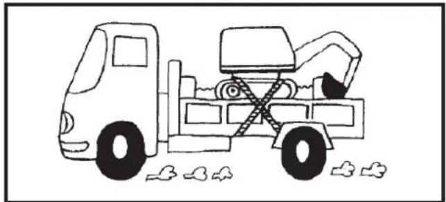
Block the tracks with blocks and tie down the excavator.
After loading the excavator onto a truck, tie the excavator's undercarriage to the truck with a heavy-duty steel cable.
- Do not brake suddenly with a loaded excavator. Fatal accidents could occur.
1.3.5. Maintenance
Before performing any maintenance on the excavator, position the machine on firm, level ground, lower the attachments, stop the engine, and release the cylinder pressure by operating the levers. When removing hydraulic components, ensure the hydraulic oil has cooled sufficiently to prevent burns.
Begin maintenance work carefully, for example, loosen screws slowly so that oil does not splash.
-
Before performing work on the engine, exhaust system, heat shield, and hydraulic system, allow the excavator to cool down sufficiently.
-
Always turn off the engine when refueling. Avoid spilling or overfilling the fuel tank.
-
Smoking is prohibited while refueling and handling the battery! Keep sparks and flames away from the fuel tank and battery. The battery emits flammable gases.
-
When the battery is discharged, it can be started by pulling the recoil starter.
-
To avoid short circuits in the battery, always remove the ground cable first and connect the positive cable first.
-
Always keep a first aid kit and a fire extinguisher handy.
-
The spilled hydraulic fluid has enough pressure to penetrate the skin and cause serious injury. Leaks from small holes can be completely invisible. Do not use your bare hands to check for leaks. Always use a piece of wood or cardboard. Wearing a mask or eye protection is strongly recommended.
If injuries occur due to hydraulic fluid leaks, seek medical attention immediately. This fluid can cause gangrene or severe allergic reactions.
-
To prevent leaks of battery acid, which contains heavy metals, do not throw away the battery.
-
Respect all laws and regulations regarding the disposal of used oils, coolants, solvents, hydraulic fluids, battery acids and batteries.
EN
- To prevent fires, do not heat hydraulic components (tanks, pipes, hoses, cylinders) before they have been emptied and washed.
- Use a face mask or eye protection to protect your eyes and respiratory system from dust and other foreign particles.

- Do not go under the excavator if it is only supported on its boom and arm or bucket. The excavator may tip over or lower due to a loss of hydraulic pressure. Always use safety struts or other suitable supports.
- Do not use asbestos-lined parts. Do not use these types of parts, even if they can be installed.
- Fire prevention:
The excavator and some attachments have components that reach high temperatures under normal operating conditions. The main source of high temperatures is the engine and exhaust system. The electrical system, if damaged or improperly maintained, can be a source of electrical arcing or sparks.
The following fire prevention guidelines will help you keep your equipment running efficiently and minimize the risk of fire.
Other fundamental aspects
- Remove all accumulated debris near hot engine exhaust components, such as the cylinder head and exhaust manifold, as well as the exhaust pipes and muffler, more frequently when working under severe conditions.
- Clean all accumulated flammable debris, such as leaves, straw, pine needles, twigs, bark, small wood chips and any other combustible material from inside the lower guards of the machine or from the lower unit structures, as well as from the area near the engine.
- Inspect all fuel lines and hydraulic hoses for wear or deterioration. Replace them immediately if they begin to leak.
- Frequently inspect electrical wiring and connectors for damage. Repair any loose or frayed wires before starting the machine. Clean all electrical connections and tighten them as needed. Inspect the exhaust system daily for leaks. Check for broken pipes and mufflers, as well as loose or missing bolts, nuts, and clamps. If exhaust leaks or broken parts are found, make the necessary repairs before starting the machine.
- Always keep a multipurpose fire extinguisher on or near the machine. Familiarize yourself with how to use the extinguisher.
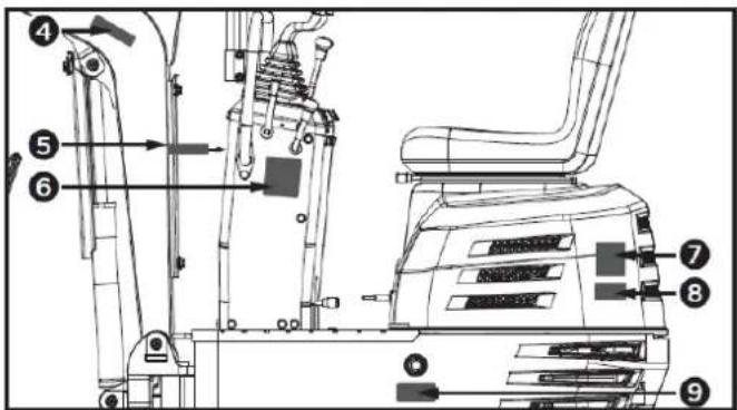
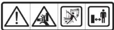
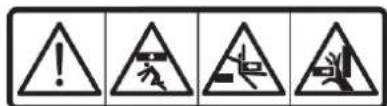
1.3.6. Hazard, warning, and precaution labels
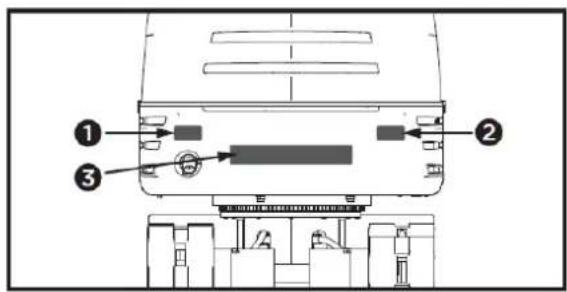
1
2

3


4

5
6
7
8

9


10

flowchart
graph TD
    A["Robot Arm"] --> B["Control Unit"]
    C["Engine Component"] --> D["Control Unit"]
    E["Drain"] --> F["Control Unit"]
    G["Hybrid Mechanism"] --> H["Control Unit"]
    I["Hybrid Mechanism"] --> J["Control Unit"]
    K["Hybrid Mechanism"] --> L["Control Unit"]
    M["Hybrid Mechanism"] --> N["Control Unit"]
    O["Hybrid Mechanism"] --> P["Control Unit"]
    Q["Hybrid Mechanism"] --> R["Control Unit"]
    S["Hybrid Mechanism"] --> T["Control Unit"]
    U["Hybrid Mechanism"] --> V["Control Unit"]
    W["Hybrid Mechanism"] --> X["Control Unit"]
    Y["Hybrid Mechanism"] --> Z["Control Unit"]
11


12

13

17
flowchart
graph TD
    A["Robot"] --> B["Lock"]
    C["Robot"] --> D["Lock"]
    E["Robot"] --> F["Lock"]
    G["Robot"] --> H["Lock"]
    I["Robot"] --> J["Lock"]
    K["Robot"] --> L["Lock"]
    M["Robot"] --> N["Lock"]
    O["Robot"] --> P["Lock"]
    Q["Robot"] --> R["Lock"]
    S["Robot"] --> T["Lock"]
    U["Robot"] --> V["Lock"]
    W["Robot"] --> X["Lock"]
    Y["Robot"] --> Z["Lock"]
    AA["Robot"] --> AB["Lock"]
    AC["Robot"] --> AD["Lock"]
    AE["Robot"] --> AF["Lock"]
    AG["Robot"] --> AH["Lock"]
    AI["Robot"] --> AJ["Lock"]
    AK["Robot"] --> AL["Lock"]
    AM["Robot"] --> AN["Lock"]
    AO["Robot"] --> AP["Lock"]
    AQ["Robot"] --> AR["Lock"]
    AS["Robot"] --> AT["Lock"]
    AU["Robot"] --> AV["Lock"]
    AW["Robot"] --> AX["Lock"]
    AY["Robot"] --> AZ["Lock"]
    BA["Robot"] --> BB["Lock"]
    BC["Robot"] --> BD["Lock"]
    BE["Robot"] --> BF["Lock"]
    BG["Robot"] --> BH["Lock"]
    BI["Robot"] --> BJ["Lock"]
    BK["Robot"] --> BL["Lock"]
    BM["Robot"] --> BN["Lock"]
    BO["Robot"] --> BP["Lock"]
    BQ["Robot"] --> BR["Lock"]
    BS["Robot"] --> BT["Lock"]
    BU["Robot"] --> BV["Lock"]
    BW["Robot"] --> BX["Lock"]
    BY["Robot"] --> BZ["Lock"]
    CA["Robot"] --> CB["Lock"]
    CC["Robot"] --> CD["Lock"]
    CE["Robot"] --> CF["Lock"]
    CG["Robot"] --> CH["Lock"]
    CI["Robot"] --> CJ["Lock"]
14

18

15
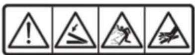
16

Pay attention to hazard, warning, and precaution labels.
- Keep hazard, warning, and caution labels clean and free of obstructing materials.
- Clean the hazard, warning, and caution labels with soap and water, and dry them with a soft cloth.
- Replace damaged or missing hazard, warning, and caution labels with new labels from your distributor.
- If a component with hazard, warning, and caution labels attached is replaced with a new part, make sure the new labels are placed in the same location as those on the replaced component.
EN
- Place the new hazard, warning, and caution labels on a clean, dry surface, pressing any bubbles toward the outer edge.
1.4. Residual risks
▲ Important
Even if it complies with the relevant product safety regulations, residual risks may exist given the characteristics of the equipment and the work for which it has been designed.
Residual risks can be minimized by following safety instructions.
- You will reduce the risk of personal injury and damage to equipment if you follow these instructions and are careful.
- Failure to comply with these safety instructions may result in injury to the operator or damage to property.
- Lack of care, improper use, or failure to comply with safety regulations can result in injuries to the hands and fingers when the wedge is in motion.
- There is a risk of hearing loss when working with the machine without protection for long periods.
Note: Even if you take preventive measures, there may be residual, non-obvious risks.
2. PRODUCT DESCRIPTION
2.1. Machine parts
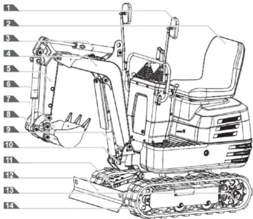
- Rearview mirror
- Operator's seat
- Arm cylinder
- Pen
- Arm
- Cylinder ladle
- Ladle
- Bucket joint
- Pen cylinder
- Rotating stand
- Shovel cylinder
- Shovel
- Caterpillars
- Front wheel
2.2. Instrument panel and control elements
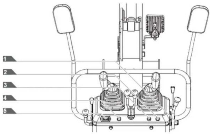
- Starter switch
- Work light switch
- Horn switch
- Power indicator
- Hour counter
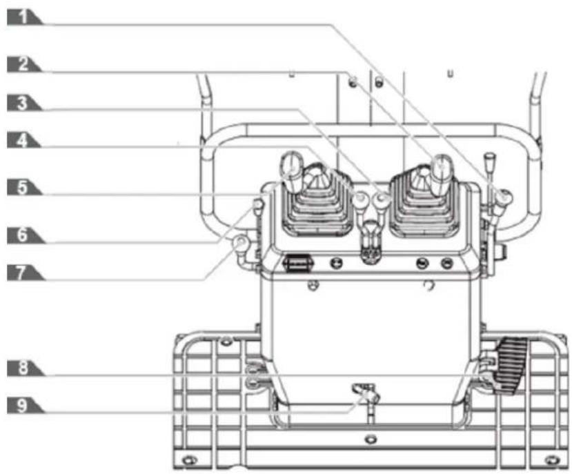
- Bucket control lever
- Control lever for the front implement (right)
- Right drive lever
- Left drive lever
- Control lever for the front implement (left)
- Gasoline engine choke control lever
- Accelerator lever
- Boom rotation pedal
- Locking lever
2.3. Main dimensions
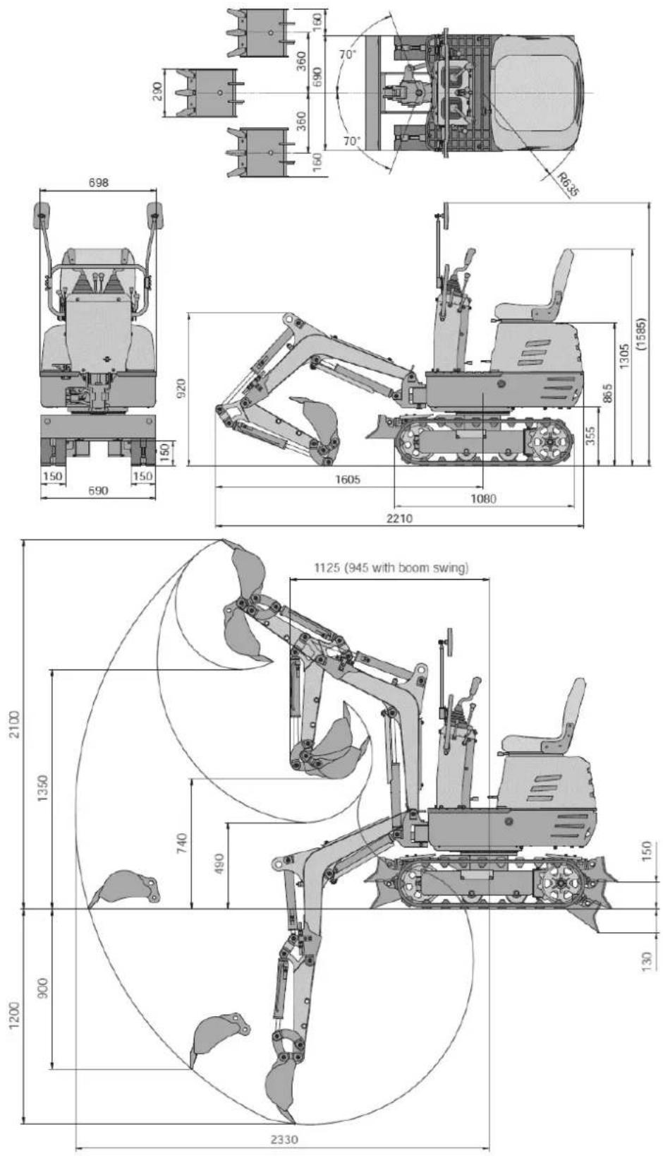
3. TECHNICAL SPECIFICATIONS
| Characteristics | ||
| Standard spoon | Volume 0.011 m3 | |
| Broad 290 mm | ||
| Digging force (bucket) | 8.8 kN | |
| Engine 306 cc | ||
| Start | Key-type start/stop switch | |
| Rotation speed 9.3 rpm | ||
| Travel speed 1.7 km/h | ||
| Slope capacity 15° | ||
| Pressure on the ground | 26.5 kPa | |
| Arm rotation/oscillation | Left 70° (L) | |
| Right 70° (R) | ||
| Type of caterpillar | Rubber tracks | |
| Pump capacity 8.3x2 L/min | ||
| Hydraulic reservoir | 12 L | |
| Fuel tank capacity | 6 L | |
| Hydraulic pressure | 17.5 MPa | |
| Parking brake | Hydraulic lock type | |
| Sound pressure level at the operator's station (LpA) | 82.5dB, K=4dB | |
| Vibration value | Arm | 2.17 m/s2, K=0.5 |
| Body | 7.65 m/s2, K=0.5 | |
| Operating weight | 637 kg | |
Note: Due to design improvements and/or changes in specifications, this manual may be modified without prior notice and without needing to change the document.
4. TECHNICAL ASSEMBLY INSTRUCTIONS
4.1. Unpacking
Remove the M8 fixing bolts securing the iron frame and remove the iron frame. Loosen the M12 fixing bolt to release the bucket and remove the straps securing the machine. Lower the machine.
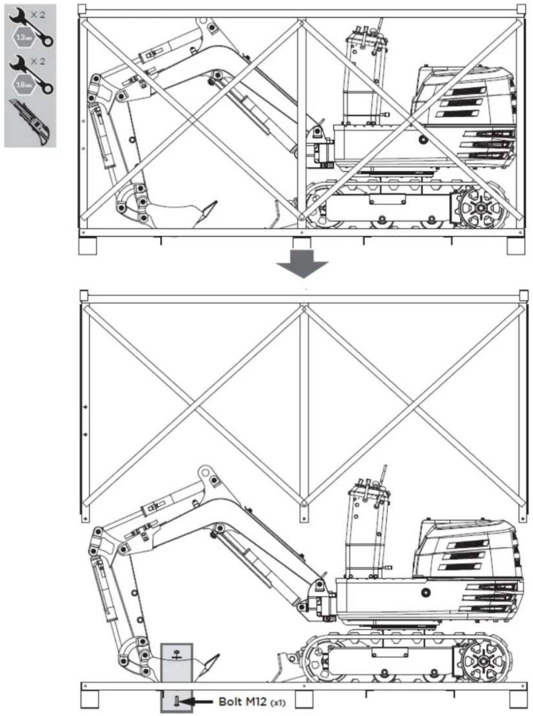
EN
The mini excavator comes partially assembled and is shipped in a carefully packaged box. Once all the parts have been removed from the box, you will need:
- Main body
- Operator's seat
- Front accessory control levers
- Transmission lever knobs
- Rearview mirror
- Handlebar
- Funnel
- Grease gun
- Fat
- Operator's Manual and Engine Manual
- Tools for spark plug installation
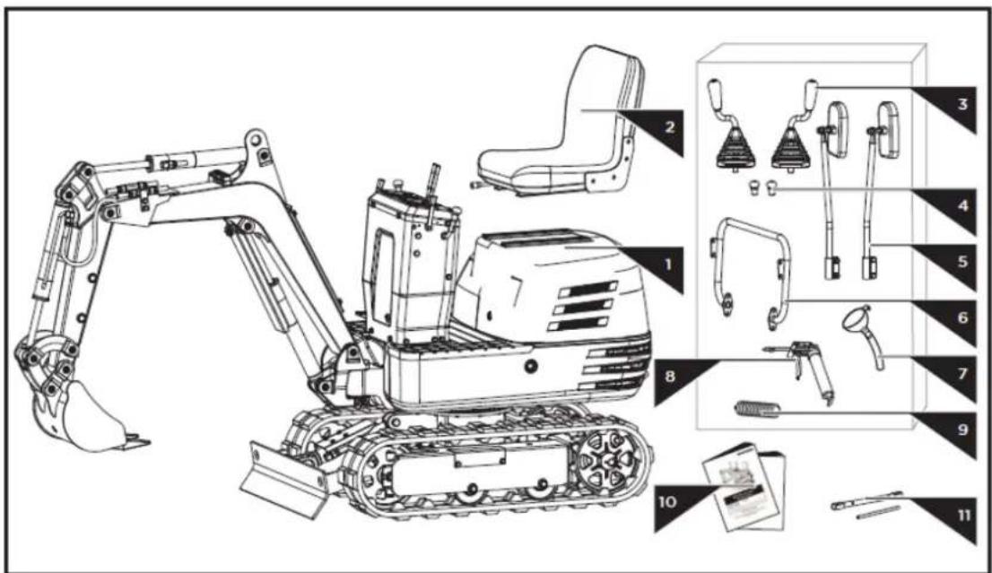
4.2. Mounting
By following the assembly instructions below, you will assemble the machine in just a few minutes.
4.2.1. Mounting the control levers
- Remove the M16 fine nut from the control lever and loosen the M8x25 fixing screw and nut on the fixing hole side.
Slide the control lever through the rubber sleeve and the M16 nut into the mounting hole on the control cabinet. Rotate it to a suitable operating angle and lock the M16 nut in place. Tighten the M8x25 fixing screw and nut from the side. Repeat these steps to mount the other lever. - Screw the knobs onto the drive levers.
EN
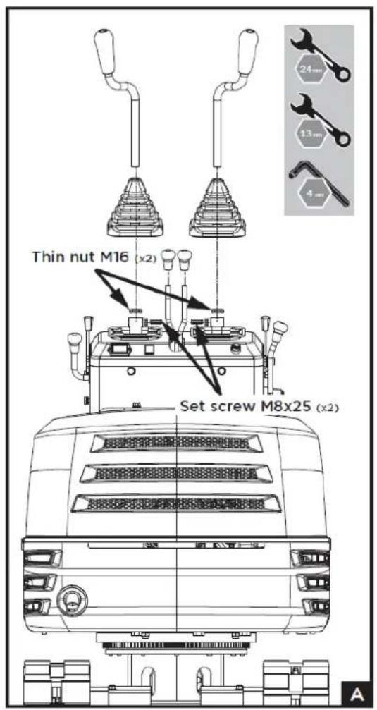
4.2.2. Handlebar assembly
- Unscrew the M10x20 bolts, flat washers, and spring washers from the control cabinet.
- Attach the handlebar to the sides of the control cabinet.
- Align the holes and secure the connection with the bolts and washers.
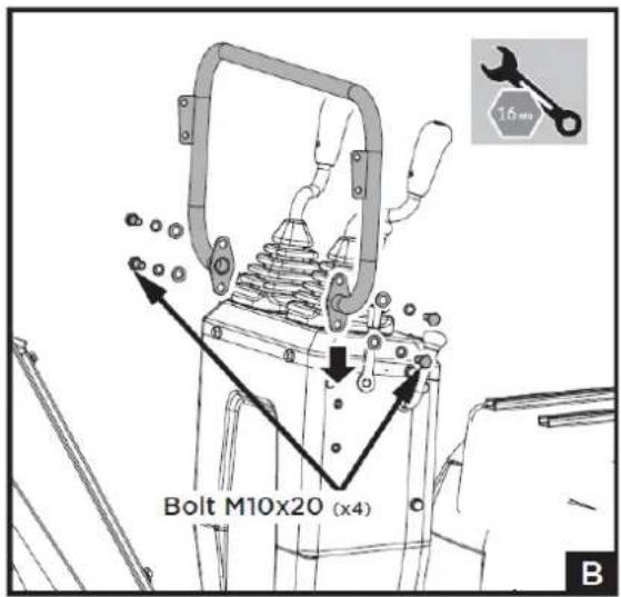
4.2.3. Rearview mirror assembly
- Unscrew the M8x30 bolts, washers, and nuts from the mirror connectors.
- Attach the connector to the handlebar mounts with the bolts, washers, and nuts, making sure the mirrors are facing backwards, as shown in figure c.
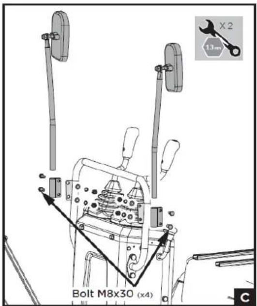
4.2.4. Operator seat assembly
- Open the hood and install the seat from front to back.
- Adjust it to a suitable position by sliding it forwards and backwards.
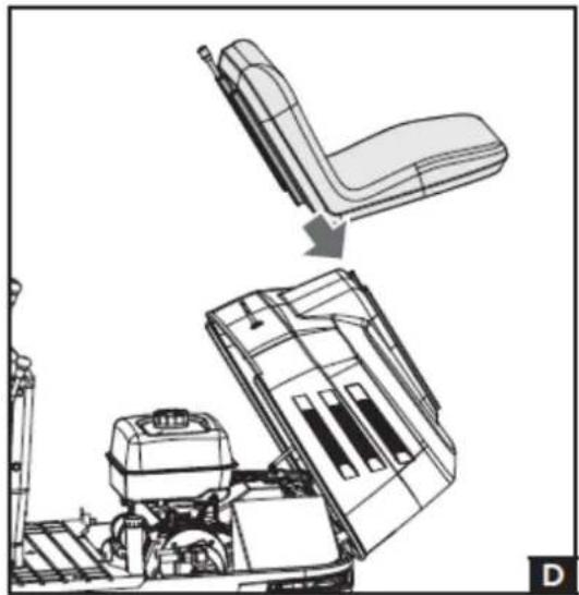
natural_image
Technical line drawing of a vehicle seat assembly showing front and side views (no text or symbols)5. OPERATING INSTRUCTIONS
5.1. Before operation
5.1.1. Handling security devices
Control lever lock
Caution: When the excavator is not in use or left unattended, be sure to lower the bucket to the ground and lock the control levers. The front attachment could fall, which is dangerous. Also remove the key.
The accessory control lever lock is located on the right side.
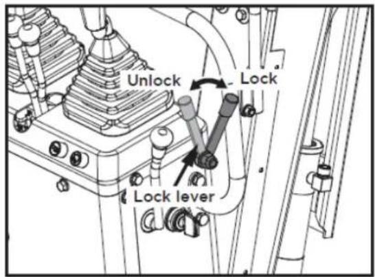
Swivel locking pin
This pin is used to lock the swivel frame. Place the locking pin in the "Lock" position and the swivel frame will be locked to the track frame.
Important: Before locking the locking pin, make sure the swivel frame and track frame are parallel to each other.
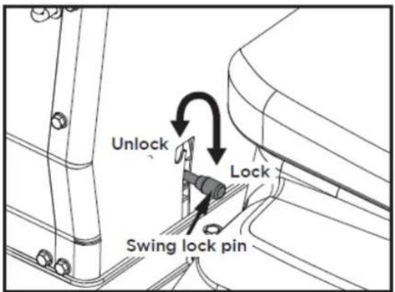
5.1.2. Daily checks
To avoid damage, it is important to check the condition of the excavator before starting it up.
EN
Caution: Perform excavator maintenance work only on level ground, with the engine off and the safety devices in the "Lock" position.
Checks
- Walk around the excavator and check for any visible damage and wear.
- Check the fuel level.
- Check the engine oil level.
- Check the hydraulic fluid level.
- Check if the air filter is clogged.
- Check the hour meter.
- Check the lighting system.
- Check the condition of the hazard, warning, and caution labels.
5.2. Engine operation
Caution
Read the "SAFE OPERATION" section at the beginning of this operator's manual.
Respect the excavator's hazard, warning, and caution labels.
Exhaust fumes are toxic. Do not leave the engine running in enclosed spaces without adequate ventilation.
Always start the engine from the operator's seat. Do not start the engine while standing next to the excavator. Before starting the engine, sound the horn to alert anyone nearby.
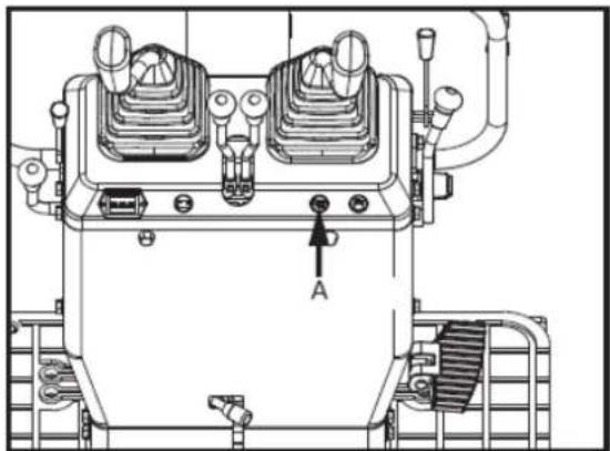
natural_image
Technical line drawing of a mechanical device with labeled component A (no text or symbols beyond label)A: Horn switch
▲ Important
Do not use starting aid sprays or similar liquids. To avoid overloading the battery and starter motor, avoid starting the engine for more than 10 seconds.
If the engine does not start within 10 seconds, adjust the interval to 20 seconds or more and try again.
5.2.1. Engine start
Caution
The operator must always perform routine checks.
EN
Note: The engine fuel valve is set to the "Open" position before leaving the factory. It is not necessary to move the fuel valve lever when starting the engine. Only if the engine fails to start, open the hood and check that the fuel valve is in the "Open" position.
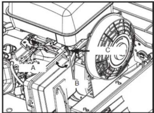
A. Closed B. Open C. Fuel
5.2.2. Start the engine as follows
- Before starting the engine, make sure all control levers are in the neutral position.
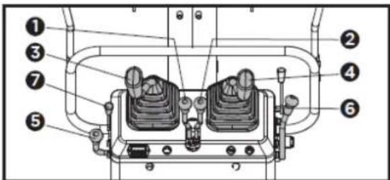
- Left drive lever
- Right drive lever
- Accessory control lever (left)
- Accessory control lever (right)
- Accelerator lever
- Bucket control lever
-
Gasoline engine choke control lever
-
To start a cold engine, move the choke control lever to the CHOKE position. To restart a hot engine, leave the choke lever in the RUN position.
- Move the throttle lever away from the SLOW position, approximately 1/3 of the way towards the FAST position.
- Activate the ignition switch by turning it fully clockwise to "START". Release the key as soon as the engine starts; it will automatically return to the "ON" position. Do not hold the key in the ignition for more than 5 to 10 seconds at a time.
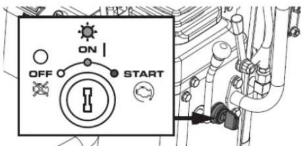
- If the choke lever has been moved to the closed position to start the engine, gradually move it to the running position as the engine warms up.
- Check if the power indicator has turned off. If the power indicator does not turn off, stop the engine and check the cause.
EN
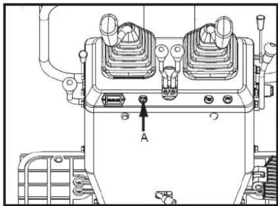
natural_image
Technical line drawing of a mechanical device with labeled components (no readable text or symbols)A. Power indicator
When the power indicator light is off, first check if the fuse is blown. If the system works normally after replacing the fuse, the battery is depleted and needs recharging. If the fuse remains blown after replacement, a professional service technician must repair the circuit.
Hour meter
The hour meter displays the total operating hours of the excavator.
Meter reading
The counter increments by 1 for each hour of operation. The electric counter continues counting even if the motor stops, but the key is in the "ON" position.
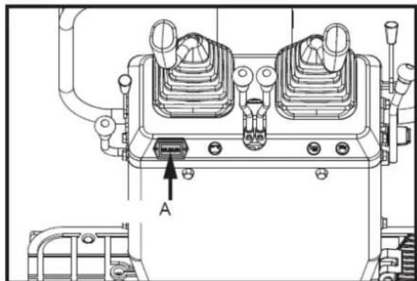
natural_image
Technical line drawing of a mechanical device with labeled component A (no text or symbols beyond label)A. Hour meter
5.2.3. Checkpoints after starting the engine
After starting the engine, but before you begin using it, check the following points:
- Set the throttle lever to the "LOW" position and let the engine idle for approximately 5 minutes. This allows the engine lubricant to warm up and penetrate all engine parts.
- Once the engine has warmed up, check the following:
a. The "Battery Charging" warning light turns off when the engine is accelerated.
b. The color of the exhaust gases is normal and no abnormal noises or vibrations are heard or felt.
c. There are no liquid leaks in the tubes or hoses.
If any of the following conditions occur, stop the engine immediately.
d. The engine revolutions increase or decrease suddenly.
e. Sudden abnormal noises.
EN
f. The exhaust gases are black.
▲ Important
In these cases, the excavator should be inspected and serviced according to the dealer's instructions.
Warning
- Let the engine warm up after starting.
- Allow the engine to warm up after starting for approximately 10 minutes without a load. If the hydraulic fluid temperature is too low, operation will be affected.
- Do not operate the excavator at full load before the engine has warmed up sufficiently.
5.3. Engine stop
Warning
Do not hold the scoop or shovel in an elevated position, as someone could accidentally touch the levers and cause serious accidents.
Lower all work tools to the ground, otherwise accidents could occur.
Let the engine idle for approximately 5 minutes to cool down.
- Place the throttle lever in the idle position.
- Carefully lower the work accessories to the ground by operating the levers.
- To stop the engine, turn the key to the "OFF" position and remove it.
5.3.1. Turn off the fuel valve
Caution
In case of emergency, or if the engine continues to run with the engine idling and the key in the off position, proceed as follows. If the engine does not stop with the key, contact your dealer.
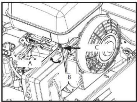
A. Closed
B. Open
C. Fuel key
Open the hood of the engine, push the stop lever back and hold it down until the engine stops.
5.4. Operating instructions
5.4.1. Control observations during operation
Stop the engine immediately if:
EN
- After starting the engine, but before starting to drive, check the following points:
There is a sudden increase or decrease in engine revolutions.
o Sudden, abnormal noises occur.
- The exhaust gases suddenly become very dark.
- Perform the following control observations during operation to ensure that everything is functioning normally.
Warning
When the engine stops suddenly, push forward the right handrail to drop the bucket, in order to prevent a malfunction that could cause injury due to the bucket falling.
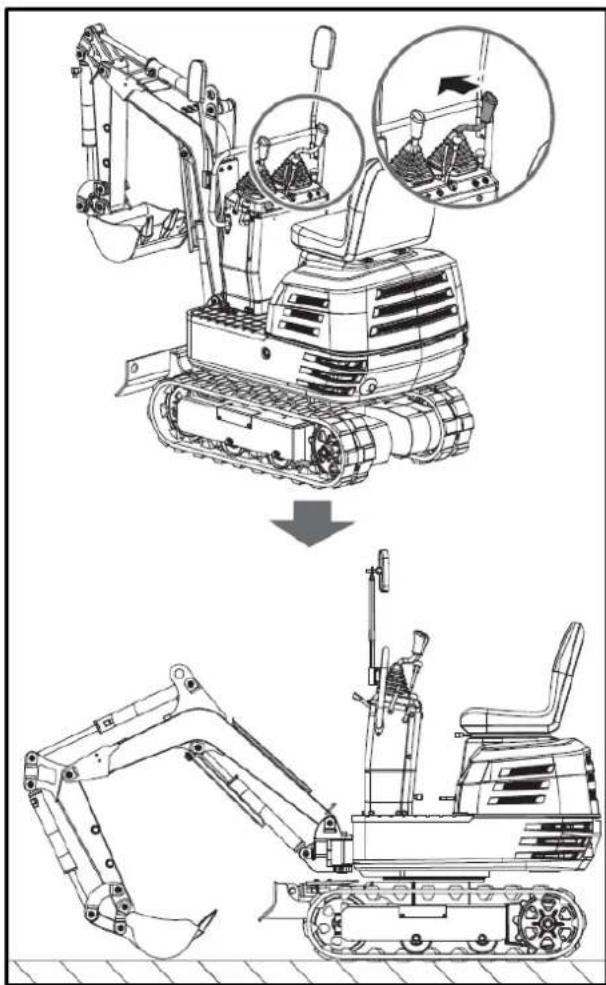
5.4.2. How the new excavator works
The operation and care of your new excavator affect its lifespan. Your new excavator has been carefully inspected and tested before leaving the factory. Nevertheless, all moving parts must be broken in during the first 50 hours of operation. Do not operate at full power or with full loads during this period. Proper break-in is crucial for achieving maximum performance and longevity. The following points must be observed at all times during the break-in period.
Do not operate at full speed or with full loads during the first 50 hours of operation.
- Let the engine warm up sufficiently in the cold station.
- Do not let the engine accelerate more than necessary.
Oil change during the break-in phase.
Lubricating oil plays a particularly important role during the break-in phase of an excavator. The numerous moving parts are still being broken in, so many fine metal particles can be generated, causing damage or shortening the lifespan of many components. Pay attention to the oil change intervals and perform them as soon as necessary.
5.4.3. Machine start-up
Caution
Only people familiar with the excavator should operate it. Do not allow anyone other than the operator to ride on the excavator.
1. Adjusting the operator's seat
Caution
Before adjusting the operator's seat, make sure that no one has their hands on the engine hood located behind the seat.
After adjusting the seat, make sure the seat adjuster has clicked into position.
Forward and backward: While holding the forward and backward adjustment lever, change the seat position forward and backward.
- Place the locking lever in the "unlocked" position.
Caution: Check the safety aspects around the excavator.
Place the locking lever in the "unlocked" position and lift the bottom of the scoop off the ground between 20 and 40 cm.
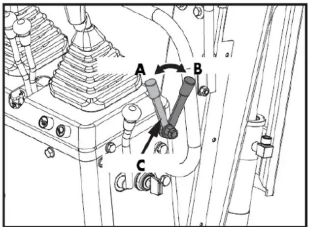
A. Unlock
B. Block
C. Locking lever
5.4.4. Work light switch
If the key is in the "ON" position, the lights will turn on when the switch is tilted.
Note: The ambient lighting of the machine must be greater than 500 lux.
EN
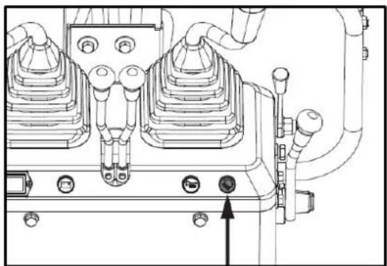
natural_image
Technical line drawing of a mechanical assembly with no visible text or symbolsWork light switch
Nighttime operation
Caution
Visibility is reduced in the dark, so work lights alone are not sufficient. Prepare additional lighting, and observe all safety rules and regulations for night work.
5.4.5. Actuating lever
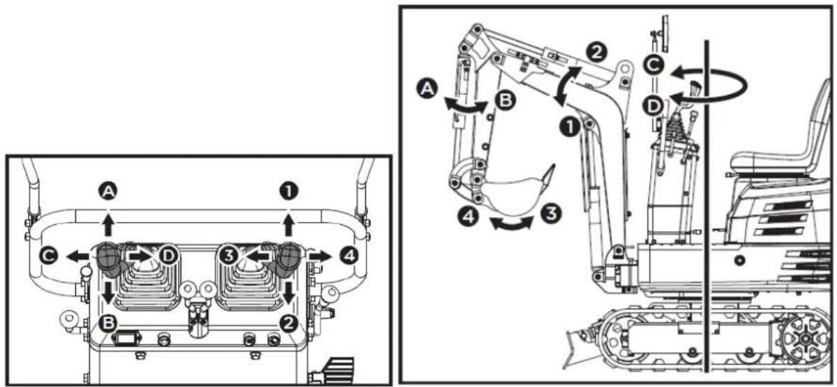
| Lever position | Motion | |
| Left front accessory control lever | TO | Arm outwards |
| B | Arm inwards | |
| C | Turn left | |
| D | Turn right | |
| Right front accessory control lever | 1 | Pump down |
| 2 | Pump up | |
| 3 | Bucket (excavating action) | |
| 4 | Ladle (tipping action) | |
5.4.6. How the pen works
- To raise the boom, pull back the implement control lever.
EN
- The boom is equipped with a shock-absorbing cylinder that prevents the excavated material from falling into the bucket.
- When the hydraulic oil temperature is low (for example, just after starting the engine), the damping function will only activate after a certain delay (approximately 3 to 5 seconds).
This condition is due to the viscosity of the hydraulic oil and is not a sign of malfunction.
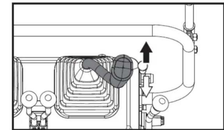
natural_image
Technical diagram of a piping system with directional arrows indicating flow or movement (no text or labels)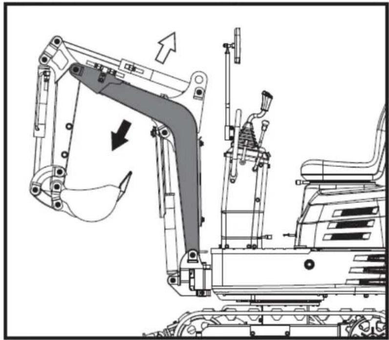
natural_image
Technical line drawing of an excavator assembly with no visible text or symbols▲ Important
When lowering the boom, make sure it does not hit the bulldozer and that the bucket teeth do not touch the bulldozer.
5.4.7. Arm operation
Pull back the left accessory control lever and the arm will retract. To extend the arm, push the control lever forward.
When retracting the arm, the movement may briefly stop when the arm is in a vertical position.
EN
This is because in this position the maximum load of the arm and bucket is reached, and the hydraulic pressure in the cylinder is not high enough.
This is a characteristic of the hydraulic system and is not a sign of malfunction.
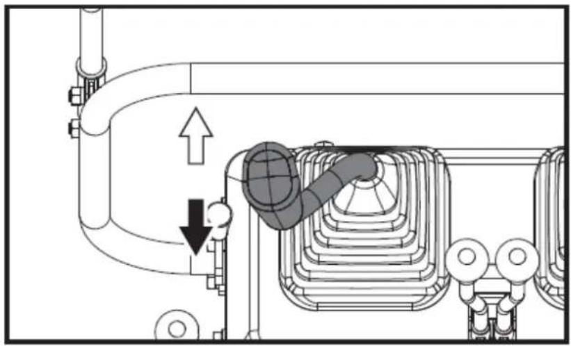
natural_image
Technical diagram of a mechanical or electrical component with pipe connections and a highlighted section showing a downward arrow (no text or symbols present)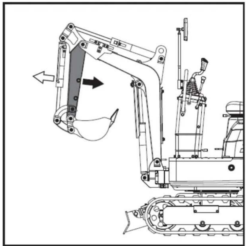
natural_image
Technical line drawing of a tracked excavator with attached mechanical components (no text or symbols)5.4.8. How the ladle works
To dig with the bucket, move the right implement control lever from the neutral position to the left. Moving the control lever to the right extends the bucket and empties its contents.
EN
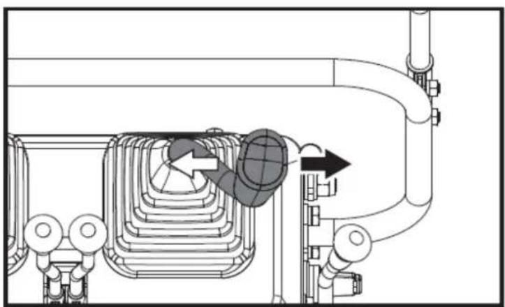
natural_image
Technical diagram of a piping system with valves and a valve mechanism (no text or labels)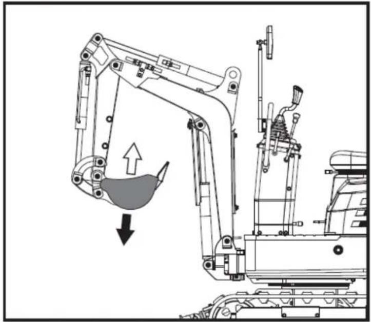
natural_image
Technical line drawing of an excavator with a downward load and component assembly (no text or symbols)5.4.9. Rotary operation (of the unit)
Caution
When working in a group, always inform others of what you are going to do before you do it. Stay clear of the work area.
▲ Important
Do not abruptly move the left implement control lever from right to left (or vice versa).
Due to the law of inertia, this causes an impact load on the swing gear and swing motor. Furthermore, it will shorten the excavator's lifespan.
Unlock the twist lock pin before performing twisting operations.
- Tilt the control lever to the left and the upper structure will rotate to the left.
- Tilt the control lever to the right and the upper structure will rotate to the right.
EN
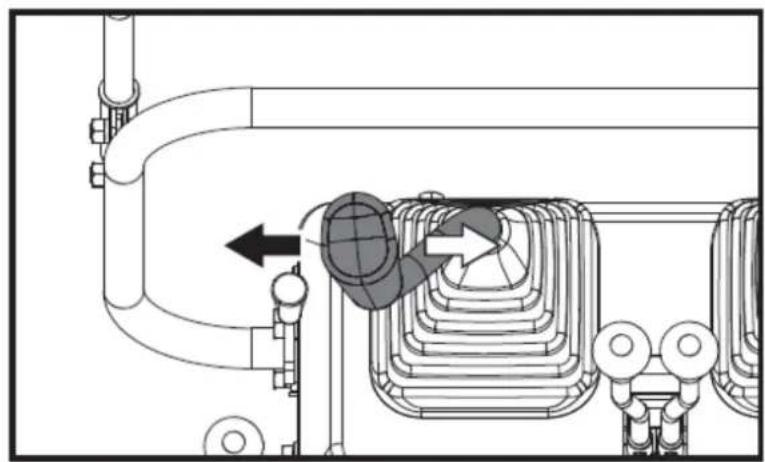
natural_image
Technical diagram of a mechanical or industrial system with pipes and a central component, no visible text or symbols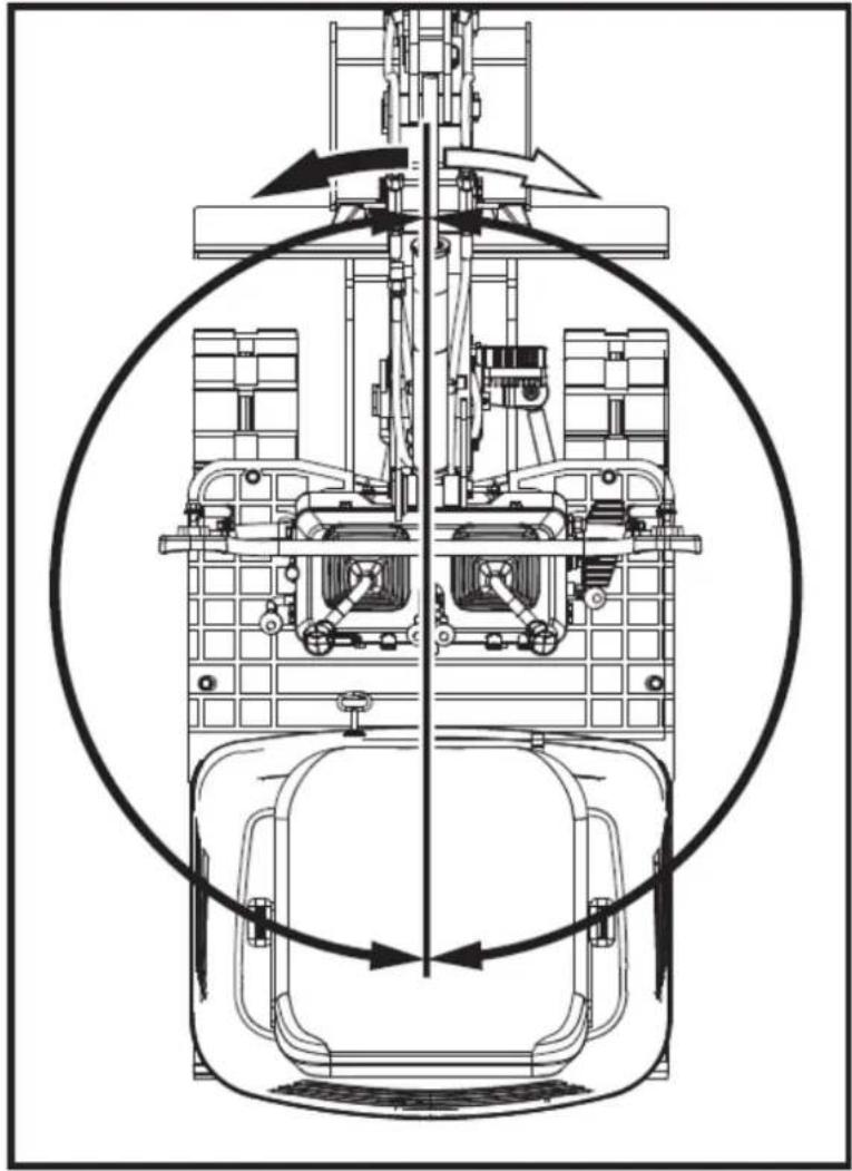
natural_image
Technical line drawing of a mechanical assembly with no visible text or symbols5.4.10. Boom rotation operation
- Step on the front of the pedal to turn the boom to the left.
- Step on the rear of the pedal to turn the boom to the right.
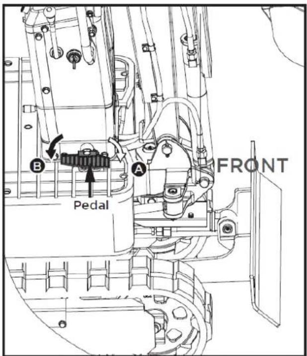
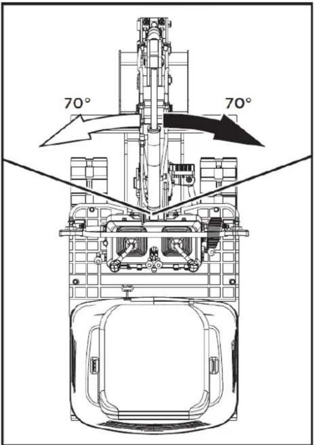
5.4.11. Boom rotation pedal
Warning
Always keep your toes inside the edge of the stirrup; otherwise, there is a possibility that your toes will become trapped between the swing frame and the boom or boom cylinder.
When the boom rotation function is not in use, fold the boom rotation pedal forward to lock it in place and prevent unexpected movements.
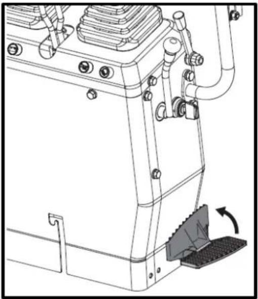
natural_image
Technical line drawing of a mechanical device with no visible text or symbols5.4.12. How the shovel works
- To raise the blade, pull back the blade control lever. Push the control lever forward to lower the blade.
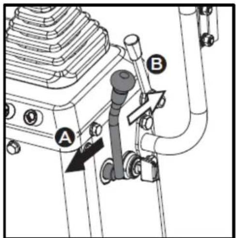
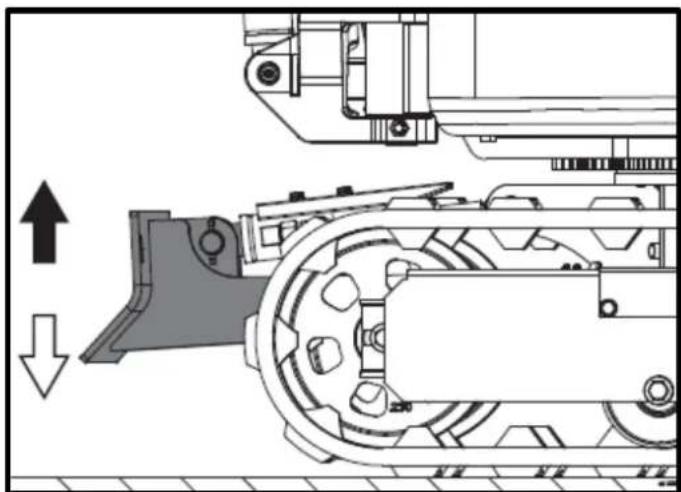
natural_image
Technical diagram of a mechanical assembly with directional arrows indicating motion (no text or symbols)- While performing earthmoving work, control both drive levers with your left hand and the shovel control lever with your right hand.
5.5. Driving
Warning
Before starting the engine, make sure there are no other people in the vicinity of the excavator.
Before starting the excavator, check the track direction. (Idler wheel and dozer blade at the front of the excavator).
Avoid traveling on a slope or working on the side of a slope.
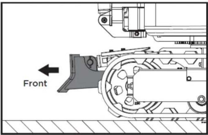
- Adjust the engine speed from idle to an intermediate speed.
- Raise the excavator and hold the shovel about 20-40 cm off the ground.
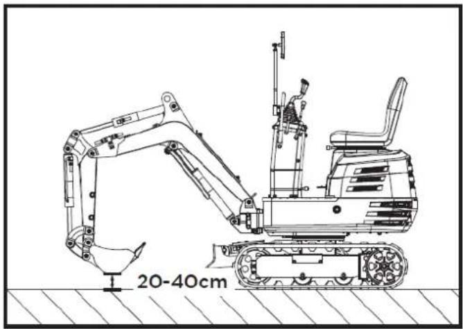
5.5.1. Driving levers (right, left)
Warning
If the rotating frame has been turned 180^ , that is, if the excavator is, from the operator's point of view, "behind", the direction of travel is opposite to the direction of driving of the levers (by activating the driving lever forward, the excavator, from the operator's point of view, will move backward).
EN
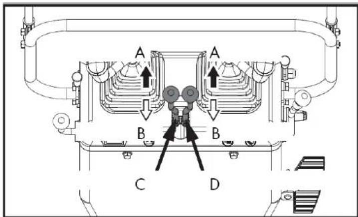
A. Go ahead
B. Back
C. Left drive lever
D. Right drive lever
By pushing both forward control levers simultaneously, the excavator moves forward.
Similarly, by pulling both reverse gear control levers simultaneously, the excavator reverses.
The front of the excavator is the direction in which the shovel is located.
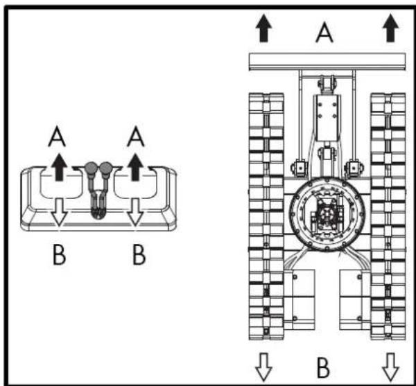
If the track gets stuck in sand or gravel while working in soft ground, lift one track with the help of the boom, arm and bucket and let the track rotate to shake off the sand and gravel.
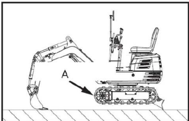
A. Turn to shake out the sand and gravel.
▲ Important
When driving over muddy terrain, if the excavator gets stuck in the mud and cannot move, it should be lifted to a safe area using the lifting strap, as shown in the following drawing.
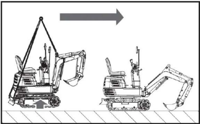
natural_image
Technical line drawing of two excavators with directional arrows indicating movement (no text or symbols)▲ Important
The excavator cannot travel on muddy roads with the rotating platform perpendicular to the tracks, to prevent them from getting stuck in the mud.
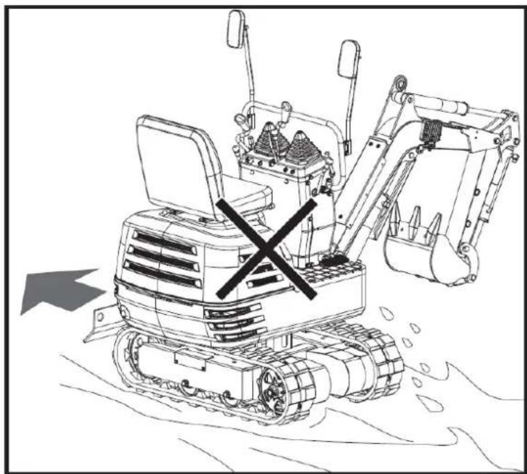
natural_image
Line drawing of a bulldozer with a cross symbol crossed out, no text or symbols present5.5.2. Turns
▲ Important
Do not change direction on steep slopes, as the excavator could tip over.
Before changing direction, pay attention to people in the work area.
pivoting motion
When the excavator is facing backwards, the direction of rotation is reversed.
EN
(For example, push the left (right) drive lever forward; the right (left) track, as seen by the operator, will move backward from the operator's position.)
Note: The illustrated movement shows a turn with the excavator facing forward.
Changing direction while stationary
- Push the left drive lever forward; the excavator will turn to the right.
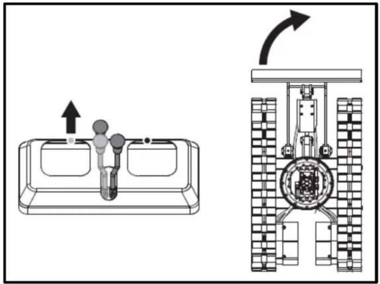
natural_image
Technical diagram showing a mechanical assembly with an upward arrow and a side-view view of a tracked vehicle (no text or symbols present)- Pull the left drive lever back; the rear of the excavator will turn to the right.
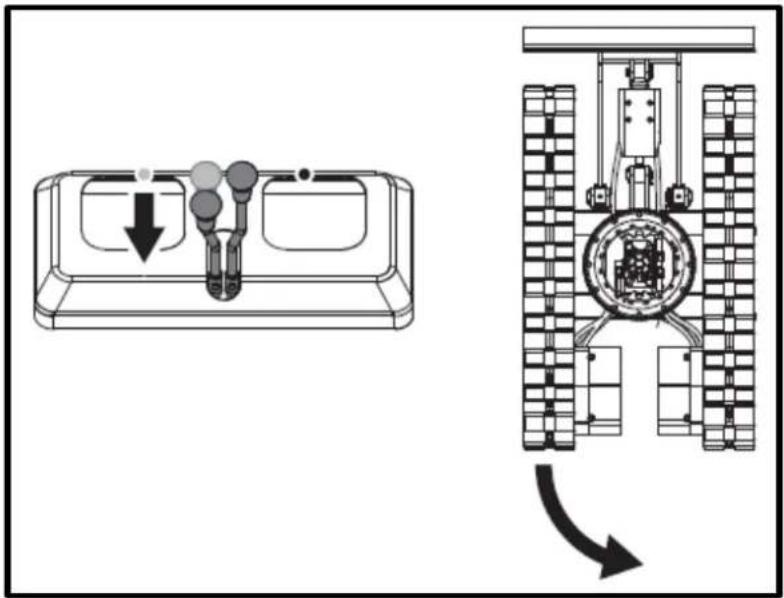
EN
Change of direction while moving
- While moving forward, pull the left drive lever back to the neutral position and continue pushing the right lever into the forward position; the excavator will turn to the left.
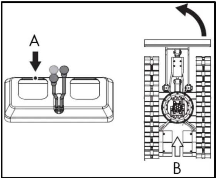
A. Neutral position B. Driving Forward
- While moving in reverse, push the left drive lever back to the neutral position and hold the right lever in the reverse position; the rear of the excavator will turn to the right.
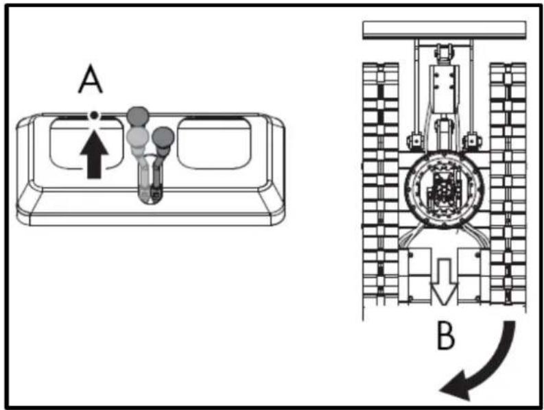
TO. Neutral position
B. Reverse
5.5.3. Turn
When both drive levers are activated in opposite directions, both tracks will rotate at the same speed, but in opposite directions, and the excavator will rotate on its own axis.
The center of rotation is the center of the excavator.
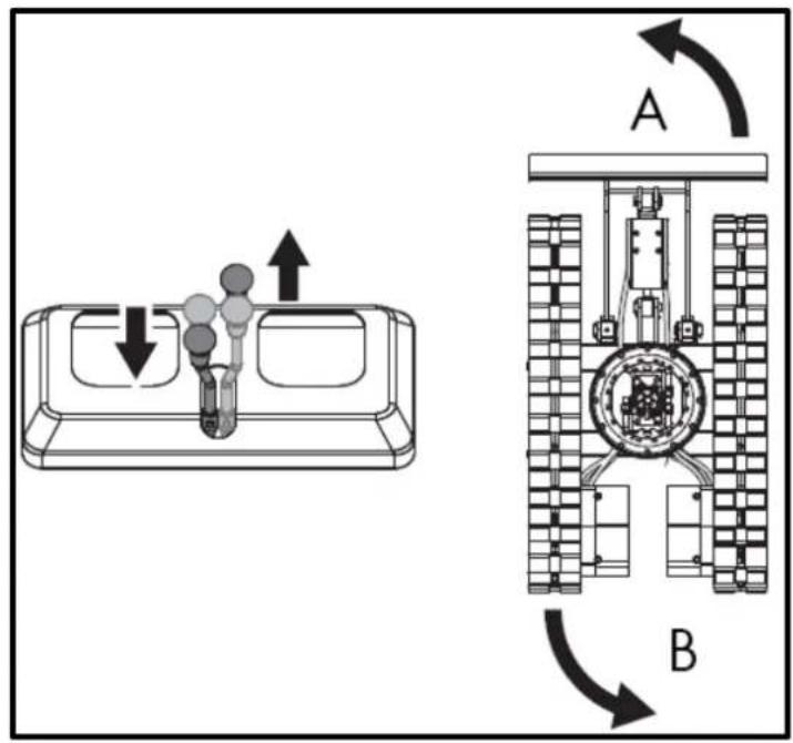
A. Left turn
B. Left turn
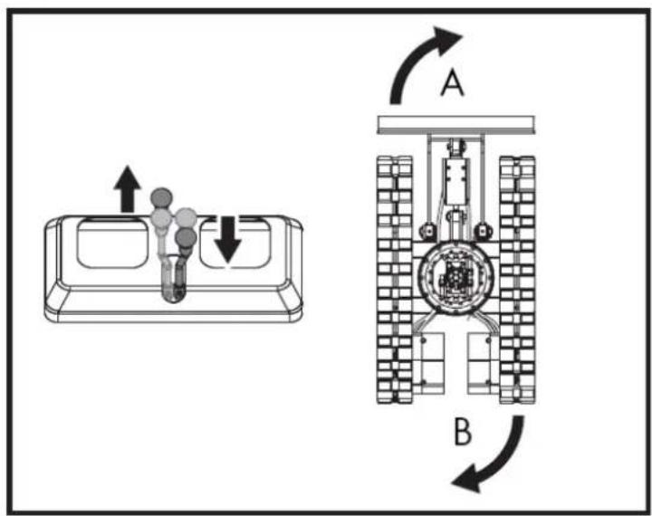
A. Turn right
B. Turn right
5.5.4. Uphill and downhill travel
When moving uphill, keep the bottom edge of the bucket about 20-40 cm above the ground. Although the excavator doesn't slip easily thanks to its tracks, it's safer to let the bucket glide along the ground when moving downhill. Always choose a slow speed when moving uphill and downhill.
Uphill travel
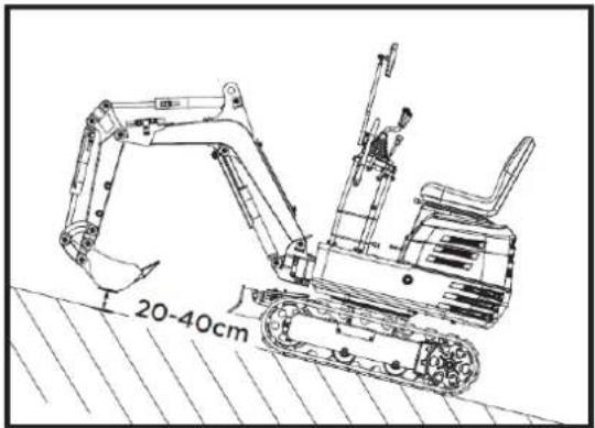
Downhill trip
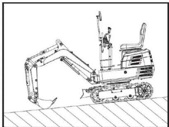
natural_image
Line drawing of an excavator on a construction ground (no text or symbols)5.5.5. Sloping parking
Warning
When parking or leaving the excavator unattended on a slope, make sure to place the bucket on the ground and all control levers in the neutral position, and then chock the tracks with wheel chocks.
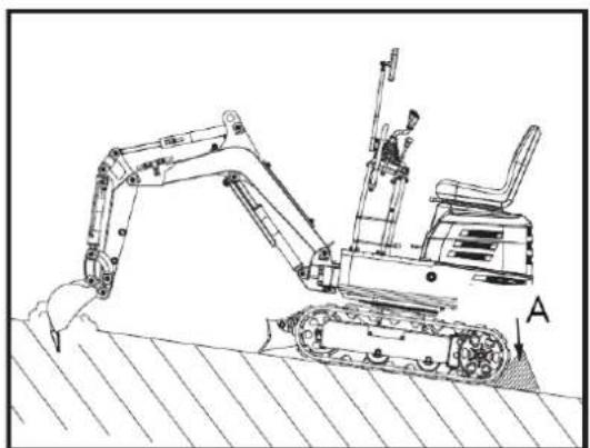
natural_image
Technical line drawing of an excavator on a sloped terrain, labeled with point A (no text or symbols present)A. Wedge
5.6. Important information about the operation of the excavator
Warning
After use, clean the machine and lubricate all moving parts. Check the oil level.
▲ Important
Do not attempt to crush concrete or rocks using the bucket's side swing. Also, avoid using the bucket's side swing to move piles of earth. At all times, avoid the following operations:
- Excavation using the machine's gravitational impact.
- Compacting gravel or soil using the dropping action of the scoop.
- Excavation using the machine's displacement power.
- Do not attempt to shake or drop the soil adhering to the scoop as shown in the explanation below. This may cause damage to the machine.
- The stuck-on soil can be shaken off when emptying the bucket by moving it through the full stroke of the cylinder. If this is not enough, rotate the arm as far as possible and move the bucket back and forth.
- Do not strike the bucket with the boom cylinder. Ensure the boom cylinder does not strike the bucket when digging deep. If necessary, rotate the upper structure so the bucket is at the rear of the machine.
- Pay attention when retracting the bucket. When retracting the bucket (for driving or transporting), avoid hitting the bucket. Avoid collisions.
- When moving the excavator, be careful that the shovel does not hit obstacles such as rocks, etc.
- These collisions considerably shorten the lifespan of the blade and the cylinder.
- Hold the machine correctly
- After stabilizing the machine with the shovel, lower the entire shovel to the ground.
- If the water or mud level rises above the top of the tracks, the swivel bearing, swivel motor gear, and ring gear may be exposed to mud, water, and other foreign objects.
- The excavator must be properly pressure washed after each use.
5.7. Transporting the excavator on a truck
Do not change direction while the excavator is on the ramp. If a change of direction is necessary, move completely off the ramp and then make the turn.
Danger
When driving forward or backward on the truck, or when rotating the top of the machine, ensure that neither the cab nor the truck doors are damaged. When the excavator reaches the point between the ramps and the truck bed, stop and move very slowly until the excavator reaches the horizontal position.
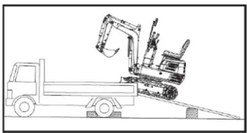
natural_image
Line drawing of a construction vehicle with an excavator on an inclined plane (no text or symbols)Danger
Move the excavator toward the truck only with the arm fully retracted. Otherwise, the truck cab could be damaged when the top of the machine rotates.
EN
Do not use the boom to lift the machine while loading or unloading the excavator from the truck. This could create a dangerous situation. After loading the machine onto the truck, lower the bucket and shovel onto the truck bed. Lock the swing frame with the swivel locking pin.
Prepare a platform for loading or unloading the excavator. Follow these steps when using ramps.
- Apply the truck's parking brakes and block the drive wheels on both sides.
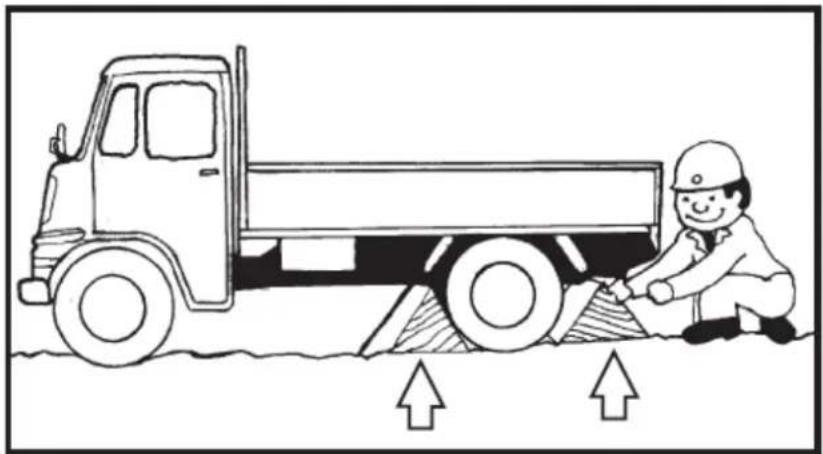
natural_image
Illustration of a truck with a worker kneeling beside it, showing structural damage or damage (no text or symbols)- Use mounting plates to secure the ramp properly. Connect the ramps directly to the truck bed.
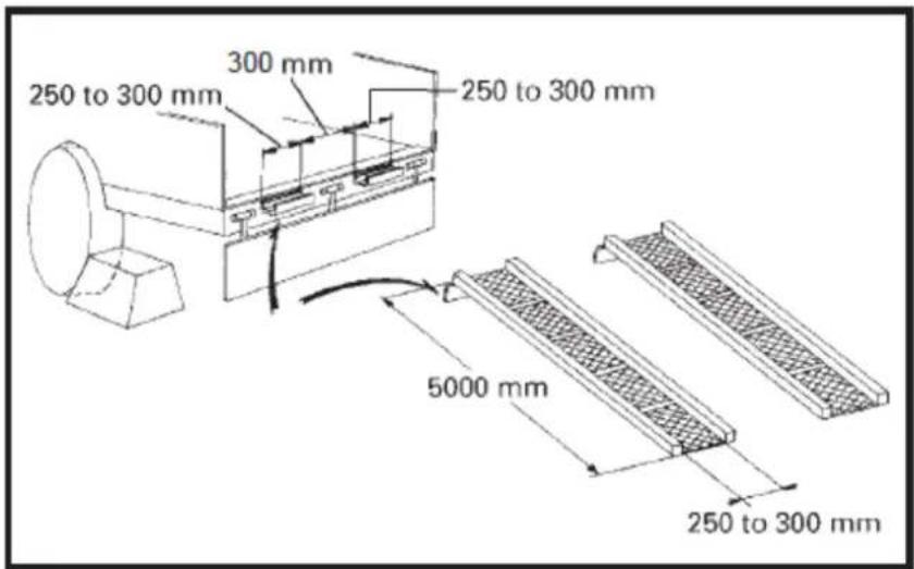
EN
- For added safety, use blocks or struts under the ramps and truck bed.
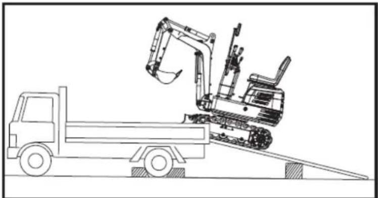
natural_image
Line drawing of a construction vehicle with an excavator on an inclined ramp (no text or symbols)-
Fully align the ramps and tracks, then slowly drive the excavator up the ramps with the front bucket at the front. After ensuring the tracks are fully on the truck bed, turn the upper part of the excavator toward the rear of the truck.
-
Lock the rotating frame with the rotating locking pin.
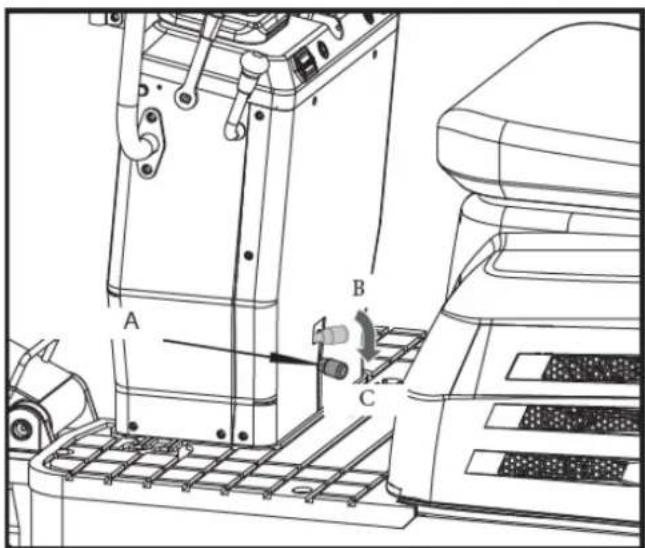
A. Swivel locking pin.
B. Unlock.
C. Block.
- Lower the bucket and shovel onto the platform and lock the boom before getting out.
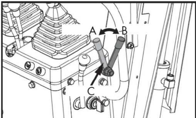
A. Unlock
B. Lock C. Locking lever
- Lock the tracks and secure the excavator.
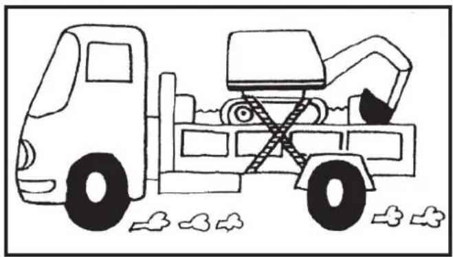
natural_image
Line drawing of a construction vehicle with an excavator and bucket, no text or symbols present- Before unloading, remove the swivel locking pin, and then lift the bulldozer and bucket off the truck bed.
5.8. Excavator lift
Danger
This document describes the correct instructions for safe operation. Read them carefully before moving the machine. Ensure that operating personnel carefully read the operator's manual.
Basic concepts for lifting with chains/belts
- The lifting and operation of the crane must be carried out in accordance with the guidelines described.
- Since the lifting accessories mentioned in these instructions are provided for reference only, standards relating to strength, control and other details are based on the respective applicable guidelines.
5.8.1. Safety considerations when lifting with chains/straps
- Do not lift loads that exceed the crane's maximum load capacity.
- Choose the appropriate rigging for the weight, size, and shape of the load.
- First assess the load's center of gravity, place the hook directly over the load, and raise the load so that the load's center of gravity is as low as possible.
- The steel cables must be fixed to the center of the hook.
- The load must be lifted vertically from the ground.
- Do not enter the work area under suspended loads and do not move the load over other people. The load should be moved in an area where it is easy to maintain balance.
5.8.2. General guidelines for lifting
Do not raise the excavator except at the 3 points indicated in the illustration.
- Lifting position. (see illustration below).
(1) Pull the pen completely back.
(2) Pull your arm completely out.
(3) Pull the spoon out completely.
(4) Turn the pen to the center position.
(5) Rotate the upper body 180^ to ensure the operator behind can see the shovel.
(6) Insert the twist lock pin.
- Fastening the chains/straps.
EN
(1) Always attach the excavator at three points. (One on the boom and one each to the right and left of the excavator blade).
Warning
The excavator must be elevated.
(2) Always use a shackle on each lifting hole when attaching straps.
(3) Use cushioning material at all points where the belts come into contact with the machine.
- Equipment
Choose components with sufficient strength.
- Elevation
(1) Raise the machine slowly and safely.
(2) Do not enter the excavator area during lifting.
(3) Raise the excavator to a horizontal position. (Adjust connections as needed.)
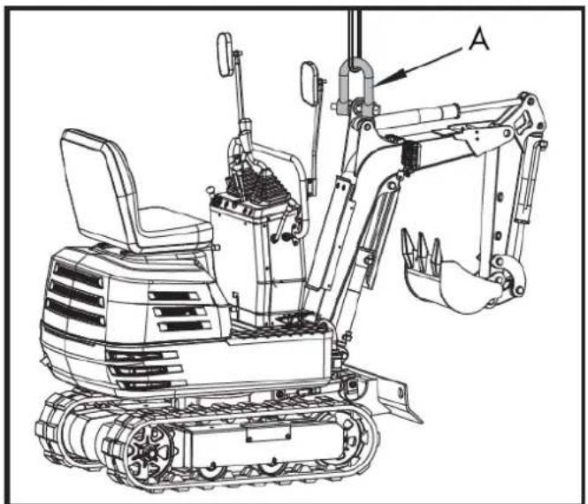
natural_image
Technical line drawing of a tracked excavator with labeled component A (no text or symbols beyond label)A. Shackle
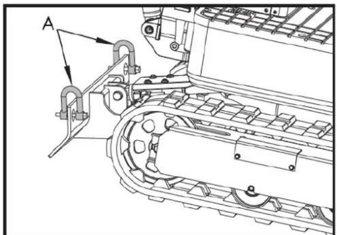
natural_image
Technical line drawing of a tracked vehicle with labeled component A (no text or symbols beyond label)A. Shackle
EN
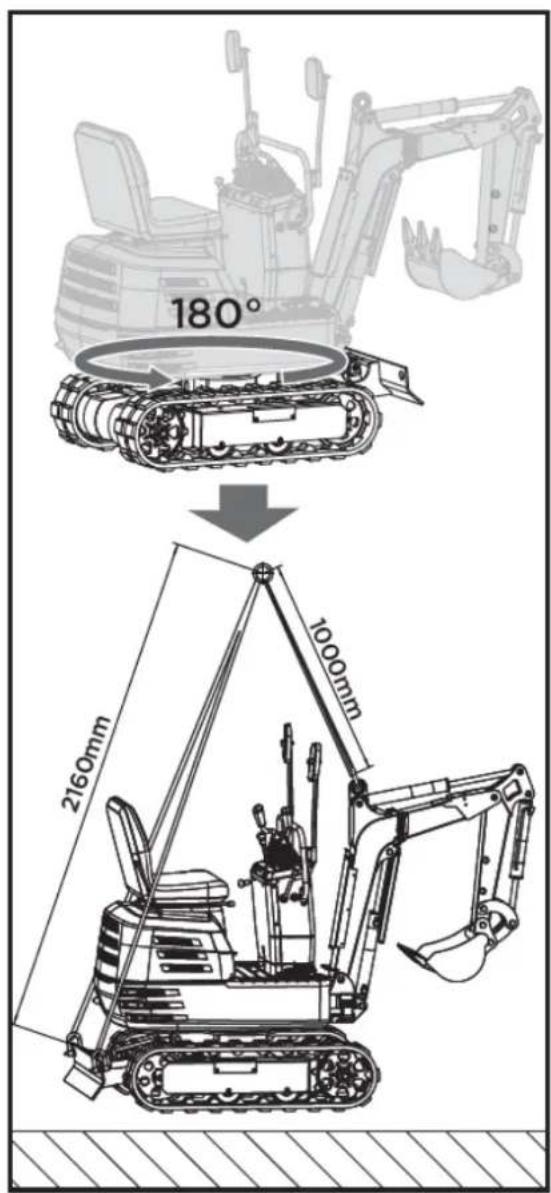
6. MAINTENANCE
Proper maintenance is essential for safe operation and to minimize potential machine problems. Follow the recommendations and inspection and maintenance schedules in this manual.
Warning
Improper maintenance, failure to correct a problem before operation, or the use of non-manufacturer-approved replacement parts can cause malfunction and serious personal injury. Always use appropriate PPE when performing adjustments or repairs.
▲ Attention
If you are unsure how to perform any of the maintenance items listed below, please contact your authorized dealer for assistance.
| Point to review | Revision | Machinery | Consequently | |||||||||||||
| 50 | 100 | 150 | 200 | 250 | 300 | 350 | 400 | 450 | 500 | 550 | 600 | 1000 | 2000 | |||
| Fuel | Check | Daily review | ||||||||||||||
| Engine oil | Check | Daily review | ||||||||||||||
| Change | ○ | ○ | ○ | ○ | ○ | ○ | ○ | ○ | ○ | ○ | ○ | ○ | ○ | ○ | Every 50 hours | |
| Hydraulic oil | Check | Daily review | ||||||||||||||
| Change | ○ | ○ | Every 1000h | |||||||||||||
| Lubrication points | Check | Daily review | ||||||||||||||
| Cooling fan | Check | Daily review | ||||||||||||||
| Power lines | Check | Daily review | ||||||||||||||
| Pneumatic cylinder/cooling fin | Clean | Daily review | ||||||||||||||
| The whole machine | Clean | Daily review | ||||||||||||||
| Battery status | Check | ○ | ○ | ○ | ○ | ○ | ○ | ○ | ○ | ○ | ○ | ○ | ○ | ○ | ○ | Every 50 hours |
| Lubrication of the teeth of the rotating | Check | ○ | ○ | ○ | ○ | ○ | ○ | ○ | ○ | ○ | ○ | ○ | ○ | ○ | ○ | Every 50 hours |
| *Air filter element | Clean | ○ | ○ | ○ | ○ | ○ | ○ | ○ | ○ | ○ | ○ | ○ | ○ | ○ | ○ | Every 50 hours |
| Change | ○ | ○ | ○ | ○ | ○ | Every 200 | ||||||||||
| Lubrication of rotating ball bearings | Check | ○ | ○ | ○ | ○ | ○ | ○ | ○ | ○ | Every 100 | ||||||
| Fuel pipes and hoses | Check | ○ | ○ | ○ | ○ | ○ | Every 200 | |||||||||
| Change | Every 2 years | |||||||||||||||
| Hydraulic return filter element | Change | ○ | ○ | Every 1000h | ||||||||||||
| Hydraulic suction filter element | Change | ○ | ○ | Every 1000h | ||||||||||||
| Spark plug | Check | ○ | ○ | ○ | ○ | ○ | ○ | ○ | ○ | ○ | ○ | ○ | ○ | ○ | ○ | Every 50 hours |
| Change | ○ | ○ | ○ | Every 500 | ||||||||||||
*Clean the air filter more frequently if used in dusty environments.
6.1. Opening and closing of pieces
6.1.1. Opening/closing the engine hood
Warning
Do not open the hood before turning off the engine. Do not touch the exhaust muffler or exhaust pipe, as you could suffer severe burns.
Turn the key in the direction indicated by the arrow, as shown in the following illustration, to open the engine hood.
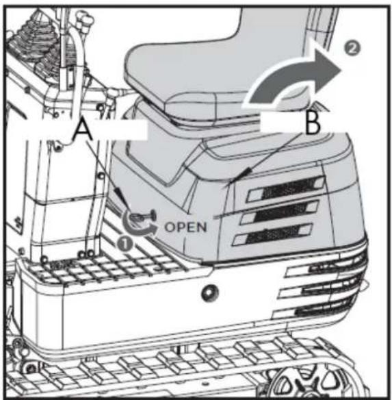
A. Engine hood key
B. Engine hood
Store the tools and operator's manual in the manual tube.
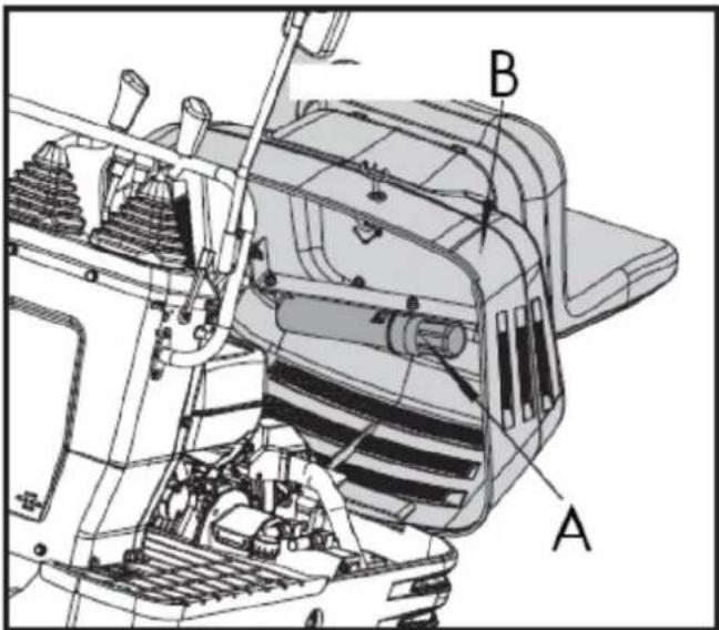
A. Operator's seat and engine hood
B. Manual tube
6.2. Daily checks
For your own safety and to ensure the long lifespan of your machine, a thorough check should be performed before each operation.
6.2.1. Check the fuel level
Caution
- Stop the engine before refueling
- Do not smoke while refueling
- Use unleaded gasoline with an octane rating of 86 or higher
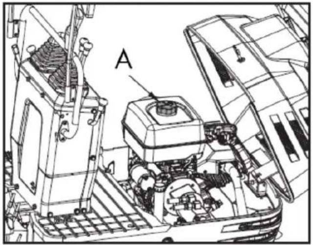
natural_image
Technical line drawing of a mechanical assembly with labeled component A (no text or symbols beyond label)A. Fuel tank cap
- Check the fuel level in the tank.
- Open the fuel tank cap and fill it with fuel.
▲ Important
- Always fill the fuel tank at the end of the workday.
- The fuel tank cap has a vent. Be sure to clean the vent when you fill the fuel tank.
If the vent is clogged with mud, the fuel tank will lose pressure.
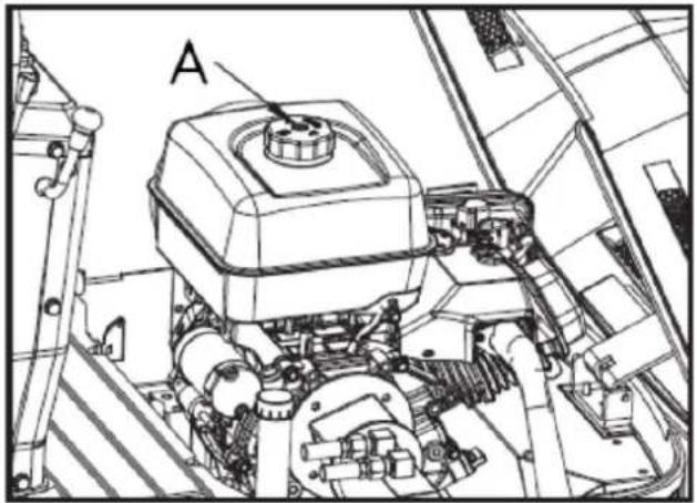
natural_image
Technical line drawing of a mechanical assembly with labeled component A (no text or symbols beyond label)A. Air vent
6.2.2. Draining water or air from the fuel tank
Danger
When draining water or air from fuel, always stay away from flames.
If the gasoline engine has not been used for a long time, it may not start when you try to start it. The following steps are necessary:
- Close the fuel tank switch.
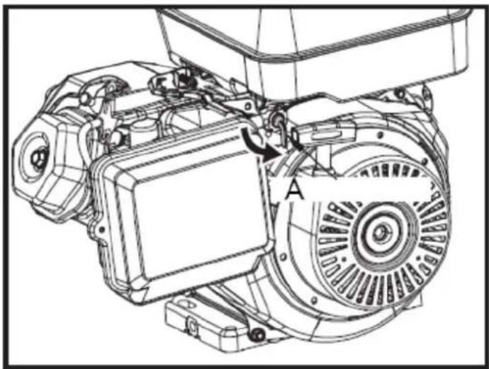
natural_image
Technical line drawing of an electric motor assembly with labeled components (no text or symbols present)A. Fuel tank switch
- Unscrew the carburetor vent port bolt to drain water or gas from the fuel.
- Close the carburetor vent bolt.
- Turn on the fuel tank switch.
- Start the engine.

natural_image
Technical line drawing of a tank interior showing engine, chassis, and structural components (no text or symbols)A. Carburetor ventilation
6.2.3. Check the engine oil level
▲ Important
Turn off the engine before checking the oil level.
Insert the oil dipstick fully into the prepared opening, remove it again, and check the oil level; if necessary, top up with oil. The machine must be on level ground when checking the oil level.
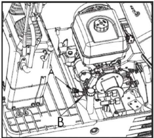
A. Oil indicator B. Filling hole
▲ Important
Use engine oil with the appropriate viscosity (according to the outside temperature).
After stopping the engine, wait five minutes and check the oil level (the excavator must be on level ground).
6.2.4. Check the hydraulic oil level
▲ Important
- First lower all implements to the ground and then stop the engine.
- Before filling with oil, clean all sand and dust around the oil port. Make sure to use the same type of hydraulic fluid.
-
The excavator has been filled with hydraulic fluid before delivery.
-
Move the excavator to level ground. Extend each cylinder rod to its center position and place the bucket in contact with the ground.
-
Check the oil level to see if it is at the center mark at a normal temperature between 10 and 30 °C.
-
The oil level is sufficient if it is between the marks.
-
If the oil level is too low, add sufficient oil through the filler hole before starting the engine. This step is important to protect the hydraulic system.
EN
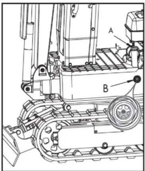
A. Fuel tank cap
B. Specified oil level
6.2.5. Lubrication points
Caution
- First lower all accessories to the ground and then stop the engine.
- While greasing, be careful not to step on the tines of the spoon.
- When performing excavation work in water, generously grease the following points. Once the work is finished, grease again.
Grease the grease fittings marked with arrows in the following illustration:
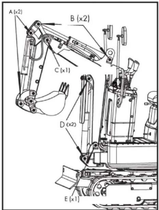
A. Spoon cylinder pin
B. Arm cylinder protrusion
C. Lower joint of the arm
D. Pen cylinder protrusion
E. Lower joint of the feather
- Lower joint of the pen: x1
- Lower arm joint: x1
- Pen cylinder protrusion: x2
- Arm cylinder projection: x2
- Spoon cylinder pin: x2
- Pen rotation pivot point: x1
- Side cylinder projection: x2
- Bulldozer blade joint pin: x2
- Spoon joint pin: x5
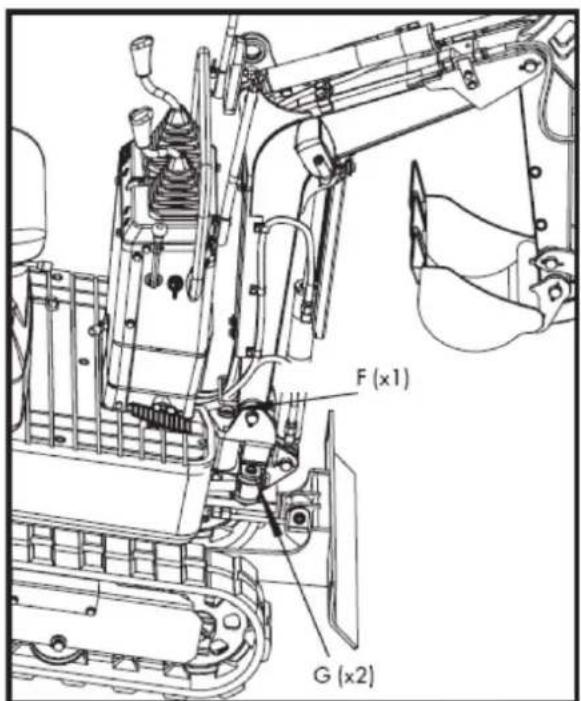
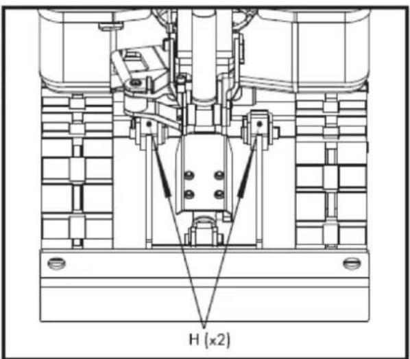
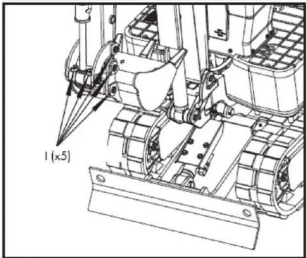
natural_image
Technical line drawing of a tracked vehicle with visible tracks and structural components (no text or symbols)
F. Boom rotation pivot point
G. Lateral cylinder protrusion
H. Blade joint pin
I. Spoon joint pin
-
Grease gun
-
Fat
Note: The grease gun and grease are stored in the box.
6.2.6. Check the cooling fan
Caution
Always stop the engine before checking the cooling fan. Wear eye protection when cleaning with compressed air.
- When it's hot, check the cooling fan more frequently to ensure it's working properly. Check for dust buildup on the cylinder head cooling fan of gasoline engines. If there's a lot of dust, use compressed air to clean it.
EN
- Check the chimney and muffler cover for rust. Check if the muffler cover's insulation layer is intact.
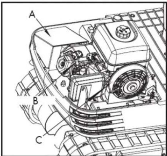
- Muffler cover 2. Cylinder head 3. Cooling fan
▲ Important
The cooling fan must be clean so that the engine does not overheat and air can circulate freely through the system.
6.2.7. Engine and electrical wiring cleaning
Caution
Always stop the engine before cleaning the wiring, cables, and motor.
Before starting, check the battery, cables and wiring, muffler, or engine for any flammable substances. Remove them completely.
6.2.8. Electrical circuit check
Check that there are no disconnections, short circuits, or loose terminals in the electrical circuit.
6.2.9. Wash the entire machine
▲ Important
Do not wash the excavator with the engine running. Water could enter the air filter and damage the engine. Make sure the air filter is kept dry.
6.3. Periodic inspections and maintenance work
6.3.1. Every 50 hours of service
Engine oil change.
Caution
First, turn off the engine and wait long enough for the oil to cool down.
- Remove the drain plug located at the bottom of the engine and drain all the oil.
▲ Important
Place a suitable container under the engine to collect the used oil. Dispose of the used engine oil according to local regulations. We suggest taking the used oil in a sealed container to your local recycling center or service station for collection.
-
Tighten the drain plug again.
-
Fill with new oil to the required level.
-
Let the engine idle for about 5 minutes. Check the engine oil level. To check the engine oil level, insert the dipstick fully into the corresponding port opening and then pull it out. If the oil level is between the two marks, no oil needs to be added.
▲ Important
Regardless of service hours, the engine oil change should be performed every year.
| Engine oil volumes | 1.1 L |
| Engine oil capacity | 306 cc - 37.2 oz (1.1 L) |
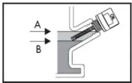
A. Maximum upper level B. Lower minimum level
Note: The total oil capacity could be up to 4 additional ounces above the volumes indicated due to the engine mounting angle and proper draining.
Note: Operating the engine with a low oil level can cause engine damage.
Recommendations regarding engine oil
- Engine oil affects performance and lifespan. Use detergent oil for 4-stroke engines.
- SAE 10W-30 is recommended for general use. Other viscosities indicated in the table may be used when the average temperature in your area warrants it.
- The SAE oil viscosity and service rating are listed on the API label of the oil container. Use engine oil rated API SERVICE SJ or higher.
EN
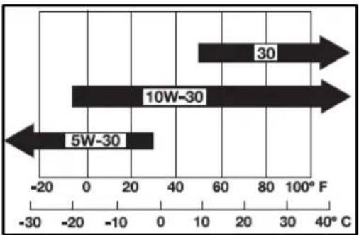
bar
| Range | Value (F) | |---|---| | 5W-30 | -20 | | 10W-30 | 0 | | 30 | 80 |AMBIENT TEMPERATURE
Battery maintenance
Caution
- Batteries contain sulfuric acid, which can cause severe burns. Avoid all contact with skin, eyes, or clothing. Antidote: External: Rinse with plenty of water. Internal: Drink large quantities of water or milk.
- Call a doctor immediately. Eyes: Rinse with plenty of water for 15 minutes and seek medical attention immediately. Keep batteries out of reach of children.
- Before inspecting or removing the battery, make sure to turn off the engine and turn the starter switch to the "OFF" position.
- When removing a battery, always disconnect the negative ground cable first. When installing a battery, do the opposite: always connect the ground cable last. This prevents a possible explosion caused by sparks.
-
Always wear eye protection when working with the battery.
-
Check if the battery shows any signs of deformation.
- If the battery is deformed, replace it.
- Clean the battery cover (vent hole) to remove dust.
- Check if the battery terminal connection is loose. If it is, tighten it again. Be careful when tightening the positive screw and make sure the tool used does not touch the cover.
Warning
Before tightening the positive screw, make sure to turn off the negative ground wire switch first.
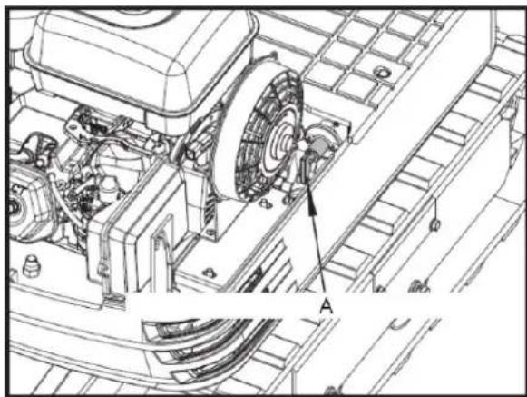
natural_image
Technical line drawing of a mechanical assembly with labeled component A (no text or symbols beyond label)A. Negative ground wire switch (OFF)
Battery charging
- To slowly charge the battery, connect the positive terminal of the battery to the positive charging terminal and the negative terminal to the negative terminal, then recharge in the usual way.
EN
- Fast charging is only for emergencies. It will partially charge the battery quickly and at high speed.
When using a fast-charging battery, it is necessary to recharge it as soon as possible. Otherwise, the battery life will be shortened.
- When replacing an old battery with a new one, use a battery of the same specifications.
Caution
- When the battery is active, the hydrogen and oxygen gases it contains are extremely explosive. Always keep sparks and flames away from the battery, especially when charging it.
- When disconnecting the battery cable, start with the negative terminal. When connecting the cable to the battery, start with the positive terminal.
- Do not check the battery charge by placing a metal object between the terminals.
Lubrication of the swashplate teeth
-
Fill with grease through the grease nozzle (at the far right).
-
Lubrication at each 90° (1.58 rad.) position of the swing frame.
-
Fill with approximately 50g of grease (approximately 20 pumps with the grease gun). Distribute the grease over the teeth.
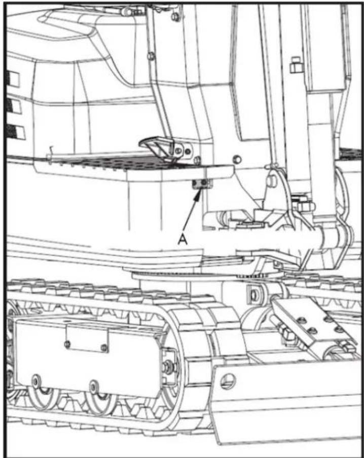
natural_image
Technical line drawing of a tracked vehicle with labeled component 'A' (no text or symbols beyond label)Grease gun (for bearing teeth)
Inspection and cleaning of the air filter
Open the engine hood and remove the dust cover. Remove only the outer element, clean the element and the inside of the housing, and reassemble everything.
During assembly, be careful to install the dust cover so that its TOP mark (arrow) is facing upwards. Do not remove the inner element.
EN
▲ Important
- If the machine is used in dusty areas, the air filter element should be inspected and cleaned more frequently than at the specified maintenance intervals.
- The air filter has a dry element; keep it free of oil.
- Do not start the engine without the air filter.
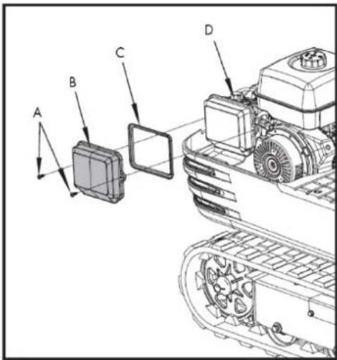
A. Fixing bolt
B. Air filter cover
C. Air filter element
D. Air filter seat
Air filter maintenance
Caution
Use eye protection.
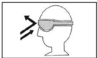
natural_image
Silhouette of a human head with an eyepatch and motion arrows indicating speed or pressure (no text or symbols)Compressed air cleaning
The compressed air pressure must be less than 205 kPa (2.1 kgf/cm ^2 ), and the cartridge must be cleaned with compressed air from the inside out until all dust deposits have disappeared.
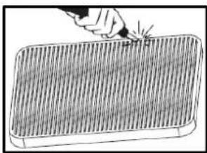
natural_image
Illustration of a hand using a tool to mark a grid pattern on a rectangular object (no text or symbols)▲ Important
If air intake remains insufficient or the exhaust gas color is abnormal even after cleaning, the air filter element should be replaced.
Spark plug check
Use a spark plug wrench to remove the spark plug and check the ignition needle for carbon deposits. If so, clean the deposits. Replace the needle if it is defective.
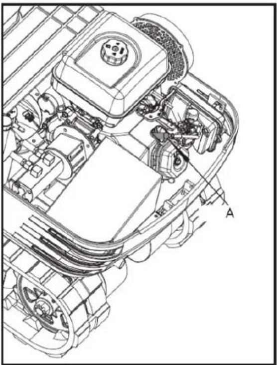
natural_image
Technical line drawing of a vehicle engine bay with labeled component 'A' (no text or symbols beyond label)Spark plug maintenance
- The use of spark plugs 99-1093, 99-113 is recommended.
Cross-references:
- Champion's cross-reference is: RN9YC (some tables show RN9YCC).
- NGK sparks plug cross reference: BPR6ES
- The cross-reference for BOSCH spark plugs is: WR6DC
Caution
Using the wrong spark plug can cause engine damage.
- When the engine is cold, disconnect the spark plug cap and remove any debris from the spark plug area with high-pressure air.
- Remove the spark plug using a 13/16-inch spark plug wrench.
- Inspect the spark plug. Replace it if the electrodes are worn or if the insulator is cracked or chipped. The spark plug gap should be adjusted to 0.027–0.030 inches.
- Install the spark plug carefully to avoid damaging the threads. Screw the spark plug in by hand until it stops turning.
- Tighten the spark plug with a 13/16-inch spark plug wrench. Tighten 1/4 turn after the spark plug seats.
Caution
A loose spark plug can overheat and damage the engine. Overtightening the spark plug can damage the cylinder head threads.
- Place the spark plug cap. Make sure the spark plug cap is securely in place.
6.3.2. Every 100 hours of service
Note: Perform all 50-hour reviews at the same time.
EN
Lubrication of the swashplate
- Grease through the corresponding grease fitting.
- Lubrication at each 90° position of the oscillating frame.
- Using the grease gun, apply 5 injections in each position.
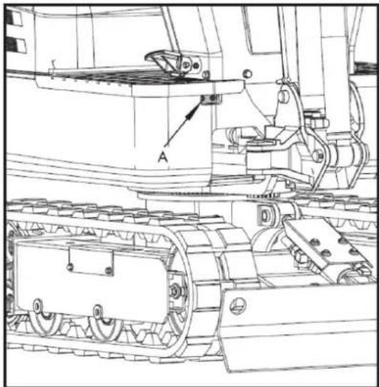
natural_image
Technical line drawing of a tracked vehicle with labeled components (no text or symbols present)A. Grease gun
6.3.3. Every 200 hours of service
Note: Perform the 50 and 100 hour maintenance at the same time.
Air filter element replacement
- Open the engine hood and remove the dust cover.
- Remove and replace the outer and inner elements with new ones.
- When reassembling, install the dust cover so that its TOP mark (arrow) is facing upwards.
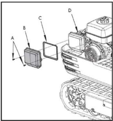
A. Fixing bolt
B. Air filter cover
C. Air filter element
D. Air filter seat
Caution
Shorten the replacement period if you use it in areas with a lot of dust or sand.
Fuel line check
- Check that all lines and hose clamps are tight and undamaged.
- If the hoses and clamps are worn or damaged, replace or repair them immediately.
6.3.4. Every 1000 hours of service
Note: Perform the 50, 100, 200, and 500 hour maintenance at the same time.
Hydraulic oil change
(Includes replacement of the suction filter and the return filter of the hydraulic reservoir).

natural_image
Technical line drawing of a tracked vehicle with labeled component A (no text or symbols beyond label)A. Suction filter
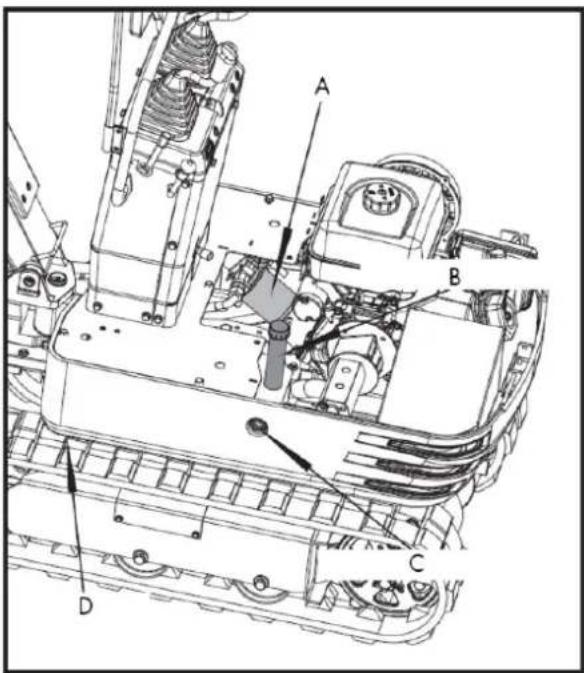
A. Return filter
B. Hydraulic oil filler
C. Hydraulic oil window
D. Drain plug
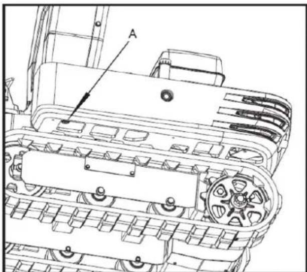
natural_image
Technical line drawing of a tracked vehicle chassis with labeled component A (no text or symbols beyond label)A. Drain plug
Check the position of the hydraulic oil window. If it is below 1/3 of the oil window position, add oil.
| Hydraulic oil volumes | Hydraulic reservoir | Approx. 10.8L |
| Total oil volumes | Approx. 14 L |
Hydraulic oil check
- Hydraulic oil change and refill.
a. Use only the recommended oils listed in the operator's manual when changing or refilling the oil.
b. When refilling the oil, do not mix oils from different brands.
- Change of the return filter and the oil.
a. The filter needs to be changed more frequently due to contamination resulting from frequent assembly and disassembly of the hoses.
b. Use the correct replacement filter.
c. Oil change according to operating hours
| Hydraulic oil return filter | Suction filter | |
| Normal work with excavator | every 1000 hours | 1000 hours |
6.3.5. Annual maintenance
Electrical wiring and fuses
- Periodically check that the terminal connections are correct.
- Loose or damaged wires can cause electrical system malfunctions. Short circuits, electrical leaks, and other costly problems could occur.
- Check the wiring and replace any damaged components immediately. If a fuse blows shortly after replacement, contact your nearest dealer. Never use a fuse other than the one specified.
Spark plug replacement
Replace after 1 year or 500 hours of use.
6.3.6. Biennial maintenance
Fuel hose replacement.
Replace the hoses and clamps.
Note: See "Fuel Line Check" in the maintenance schedule every 200 hours
6.4. Other adjustments and replacements
6.4.1. Track adjustment
To loosen the tracks, follow this procedure:
- Remove the side plate cover and loosen the M20 nut inside using a 30mm wrench.
- Adjust the M20x120 hex bolt and turn it clockwise to tighten the track; the track loosens when turned counterclockwise.
- After adjusting, tighten the M20 nut with a wrench.
Caution
Do not go under the excavator. Note: The tightening torque should be between 98 and 108 Nm.
- Install the side plate cover.
▲ Important
- If the tracks are too tight, wear increases.
EN
- If the tracks are too loose, the track shoes can collide with the sprocket and wear increases.
- The caterpillar may become dislocated or come out.
- Clean the caterpillar after each use.
- If track tension increases due to mud buildup, lift the track using the boom, arm, and scoop, idle the engine, and carefully remove mud from the track, especially from the joint plate openings.
Tighten the tracks as specified
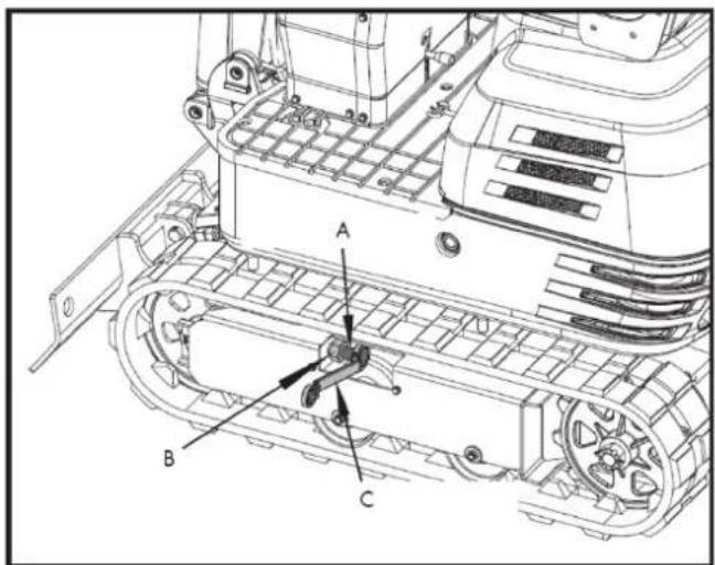
A. M20x120 screw
B. M20 Nut
C. 30 mm adjustable wrench
- Tension the track in the raised position so that the clearance (the gap between the track roller and the inner surface of the track) is 10 to 15 ~mm (see illustration). In this case, the track joint is positioned at the top center, between the idler wheel and the sprocket.
Danger
- Do not work under the machine in these conditions.
- For your safety, do not rely on devices with hydraulic support, as they may leak, fall suddenly, or lower accidentally.
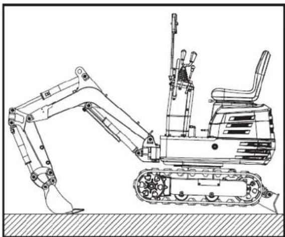
natural_image
Technical line drawing of an excavator with tracked arm and base mount (no text or symbols)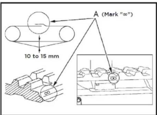
A. Union
▲ Important
- Make sure there are no obstacles, such as stones, caught in the track. Remove any such obstacles before adjusting the track tension.
EN
- Track seam. The ends of the rubber track are joined with a seam. When adjusting the tracks, the seam should be positioned at the top center, between the idler wheel and the sprocket.
If the seam is not positioned correctly, the tracks will be too loose and will need to be readjusted.
- Rotate the track once or twice after adjustment to check the tension.
- In addition, the following points should be taken into account when adjusting the rubber tracks.
☐ (1) If the track loosens by more than 0.98 inches (25 mm), readjust it.
☐ (2) Check the track tension 30 hours after initial use and readjust if necessary. Thereafter, check and adjust it every 50 hours of service.
Special information on the use of rubber tracks
- When turning, it is preferable to make a slow turn. Avoid sharp turns to reduce wear on the tracks and the entry of dirt.
- If there is too much dirt and sand clogging the tracks, move the machine back a short distance in a straight line to dislodge the dirt and sand, and then you can turn.
- Avoid using rubber tracks on riverbeds, stony ground, reinforced concrete, and iron plates. The rubber can be damaged and increase wear on the tracks.
6.4.2. Change the cube
Caution
- When removing or installing the coupling pins, shavings may be generated. Always wear gloves, safety glasses, and a hard hat.
- When changing equipment with the engine running, always work in a team of two people.
One person sits in the operator's seat and the other works on the machine.
- Do not use your fingers to center the holes, as they could be injured or even cut in case of sudden or uncontrolled movements.
- Read the accessory manual to ensure proper and safe operation when installing other accessories.
6.4.3. Fuses
Fuse replacement
A slow-blow fuse is provided to protect the electrical circuits. If the fuse blows, check the electrical circuits for any problems and replace it with a new, compatible slow-blow fuse.
- Remove the fuse box cover.
- Replace the blown fuse with a new one of the same capacity.
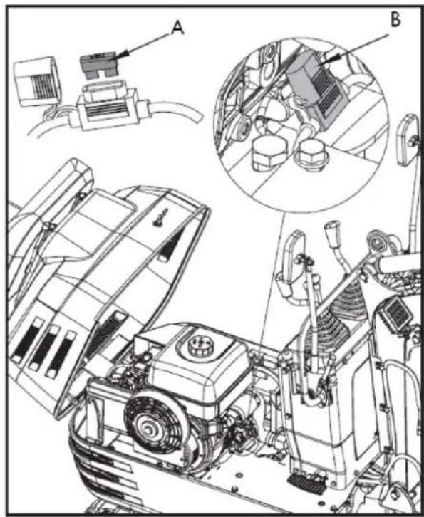
natural_image
Technical line drawing of a mechanical assembly with labeled components (A and B), showing exploded view and internal components without any readable text or symbols.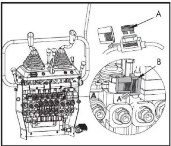
A. Fuse B. Fuse box
Capacities of fuses and circuits
| N. | Ability | Circuit |
| 1. | 10A | Working relay fuse |
| 2. | 10A | Work lamp fuse, horn, and hour meter |
6.4.4. Operation in cold conditions
Cold weather operation preparation
- Replace the engine oil and hydraulic oil with others of viscosities suitable for cold climates.
- In cold weather, battery power decreases and the battery fluid can freeze if the battery is not sufficiently charged.
To prevent the battery fluid from freezing, make sure to keep the battery charged to at least 75% or more of its capacity after operation.
To facilitate the next start-up, it is recommended to keep the battery stored in closed or heated rooms.
Procedure after the work has been completed
Thoroughly clean the excavator after use and dry it with a cloth. Otherwise, mud and dirt on the tracks could freeze if the temperature drops below 0^ C. In that case, the excavator will be unusable. Store the excavator in a dry place; if this is not possible, store it on wooden planks or mats. If the excavator is stored on wet or muddy ground, the tracks could freeze overnight. In that case, the excavator will be unusable.
In addition, the piston rods of the hydraulic cylinders must be wiped dry. Otherwise, serious damage could occur if dirty water leaks through the seals.
6.5. Long-term storage
Caution
- Do not clean the excavator with the engine running.
- To avoid the danger of exhaust fume poisoning, do not operate the engine in an enclosed building without adequate ventilation.
- When storing the excavator, remove the key from the ignition switch to prevent unauthorized use and injury.
Storage
If the excavator is to be stored for an extended period of time, observe the following procedures:
- The entire excavator must be thoroughly cleaned and, in all cases, stored indoors. If the excavator must be stored outdoors, place wooden planks on level ground, position the excavator on the planks, and cover it completely.
- Perform an oil change and grease the excavator.
- Grease the visible sections of the piston rods thoroughly.
- Remove the battery and store it indoors.
▲ Important
Wash the excavator after stopping the engine. If you wash the excavator with the engine running, water can enter the air filter through the air intakes, causing engine problems. Carefully wash the air filter, but do not splash water on it.
Subsequent use
Please observe the following procedures when using the machine after prolonged storage
- Clean the grease from the rods of the hydraulic cylinders.
- Start the engine and activate the implements and the no-load drive mechanism to circulate the hydraulic oil. (If the machine is stored for more than one month, follow steps (1) and (2) once a month.)
6.6. Periodic replacement of important components
To ensure safe operation, it is strongly recommended that you inspect and service the machine at regular intervals. For added safety, ask your dealer to replace the following important components.
These parts are prone to material degradation or wear over time. It is difficult to assess the degree of deterioration during routine inspections. Therefore, they must be replaced with new ones, regardless of whether the wear is visible after a certain period of use.
If any of them are found to be worn even before the specified use, they must be repaired or replaced in the same way as the other parts.
If any of the hose clamps are found to be deformed or cracked, they must also be replaced.
For hydraulic hoses that do not require periodic replacement, inspect them according to the following points. If you detect any problems, tighten or replace them.
When replacing hydraulic hoses, replace their O-rings and seals with new ones.
For replacement of major parts, please contact your dealer.
During subsequent periodic inspections, also check the fuel hoses and hydraulic hoses.
| Inspection interval | Checkpoints |
| Daily checks | Oil leaks at the connections and points of the fuel and hydraulic hoses. |
| Every month | Oil leak at the connections and points of the fuel and hydraulic hosesDamage to fuel and hydraulic hoses (cracks, abrasions) |
| Every year | Oil leak at the connections and points of the fuel and hydraulic hosesInterference, deformation, degradation, torsion and other damage (cracks, chafing) of the fuel and hydraulic hoses |
List of important components that must be replaced every 4000 hours of use or every 2 years. Contact your authorized dealer for maintenance.
- Hydraulic hose (suction)
- Hydraulic hose (supply)
- Hydraulic hose (boom cylinder)
- Hydraulic hose (arm cylinder)
- Hydraulic hose (bucket cylinder)
- Hydraulic hose (rotating cylinder)
- Hydraulic hose (excavator cylinder and track cylinder)
- Hydraulic hose
- Hydraulic hose (rotary motor)
Note: To avoid serious damage to the hydraulic system, use only manufacturer-approved hydraulic hoses.
6.7. Recommended oils
6.7.1. Fuel recommendations
Use unleaded gasoline with an octane rating of 86 or higher. These engines run best on unleaded gasoline.
Do not use old or contaminated gasoline or mixtures of oil and gasoline. Prevent dirt or water from entering the fuel tank. Use only suitable and properly labeled fuel containers.
Maximum recommended ethanol content: 10%. Not compatible with E15.
6.7.2. Recommendations regarding engine oil
Engine oil affects performance and lifespan.
Use detergent oil for 4-stroke automobiles.
SAE 10W-30 is recommended for general use.
Other viscosities indicated in the table may be used when the average temperature of your area justifies it.
The SAE oil viscosity and service rating are listed on the API label of the oil container. Use engine oil rated API SERVICE SJ or higher.
AMBIENT TEMPERATURE
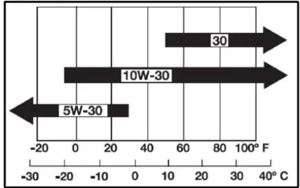
bar
| Range | Value (F) | |---|---| | 30 | 60 | | 10W-30 | -20 | | 5W-30 | -10 |6.7.3. Recommendations regarding hydraulic oil
▲ Important
Prior to delivery, the hydraulic oil used was of ISO viscosity grade 32.
Recommended hydraulic oil type:
10W AW32
ASLE H-150
ISO 32
6.7.4. Recommendations on fats
| Application | Shell | Mobile | Exxon |
| Fat | Shell Alvania EP2 | Mobilux EP2 | BEACON Q2 |
6.8. Lifting capacity
- Lifting capacities are based on ISO 10567 and do not exceed 75% of the machine's static tilt load or 87% of the machine's hydraulic lifting capacity.
- The races are as follows.
a. (1) The load point corresponds to the front bolt portion of the arm.
b. (2) The machine positions are (i) on the front (blade up), (ii) on the front (blade down) and (iii) on the side.
c. (3) The operating cylinder is the boom cylinder.
- The loads of the excavator bucket, hook, sling, and other lifting accessories are taken into account.
Machine conditions: Without bucket, the rest according to standard regulations.
Warning
It is forbidden to lift loads exceeding the values indicated in the lifting capacity tables.
The values shown in the table are only valid on smooth, hard ground. When lifting loads on soft ground, the machine may tip over because the load is concentrated on only one side of the machine.
The values in the table are calculated at the end of the boom without the bucket. To determine the allowable loads for machines with a bucket, the weight of the bucket must be subtracted from the values in the table.
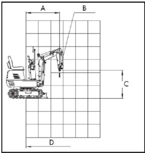
A. Radius of the elevation point
B. Elevation Point
C. Height of the elevation point
D. Axis of rotation
Lifting capacity
(i) Front (leaf facing upwards)
kN(kg)
| Height(mm) | Load radius (mm) | ||||||
| 0 | 380 | 760 | 1140 | 1520 | 1900 | 2280 | |
| 2400 | |||||||
| 2000 | |||||||
| 1600 | 1.1(110) | ||||||
| 1200 | 1.1(110) | ||||||
| 800 | 1.7(170) | 1.1(110) | 0.8(80) | ||||
| 400 | 1.6(160) | 1.0(100) | 0.8(80) | ||||
| 0 | 1.6(160) | 1.0(100) | |||||
| -400 | 3.4(340) | 1.6(160) | 1.0(100) | ||||
| -800 | 1.2(120) | ||||||
| -1200 | |||||||
| -1600 | |||||||
(ii) Front (leaf facing down)
kN(kg)
| Height (mm) | Load radius (mm) | ||||||
| 0 | 380 | 760 | 1140 | 1520 | 1900 | 2280 | |
| 2400 | |||||||
| 2000 | |||||||
| 1600 | 1.3(130) | ||||||
| 1200 | 1.3(130) | ||||||
| 800 | 2.1(210) | 1.5(150) | 1.4(140) | ||||
| 400 | 2.7(270) | 1.8(180) | 1.4(140) | ||||
| 0 | 2.8(280) | 1.9(190) | |||||
| -400 | 4.2(420) | 2.5(250) | 1.6(160) | ||||
| -800 | 1.2(120) | ||||||
| -1200 | |||||||
| -1600 | |||||||
(iii) Top
kN(kg)
| Height(mm) | Load radius (mm) | ||||||
| 0 | 380 | 760 | 1140 | 1520 | 1900 | 2280 | |
| 2400 | |||||||
| 2000 | |||||||
| 1600 | 1.0(100) | ||||||
| 1200 | 1.0(100) | ||||||
| 800 | 1.4(140) | 0.9(90) | 0.6(60) | ||||
| 400 | 1.3(130) | 0.9(90) | 0.6(60) | ||||
| 0 | 1.2(120) | 0.8(80) | |||||
| -400 | 2.4(240) | 1.2(120) | 0.8(80) | ||||
| -800 | 1.2(120) | ||||||
| -1200 | |||||||
| -1600 | |||||||
Wiring diagram
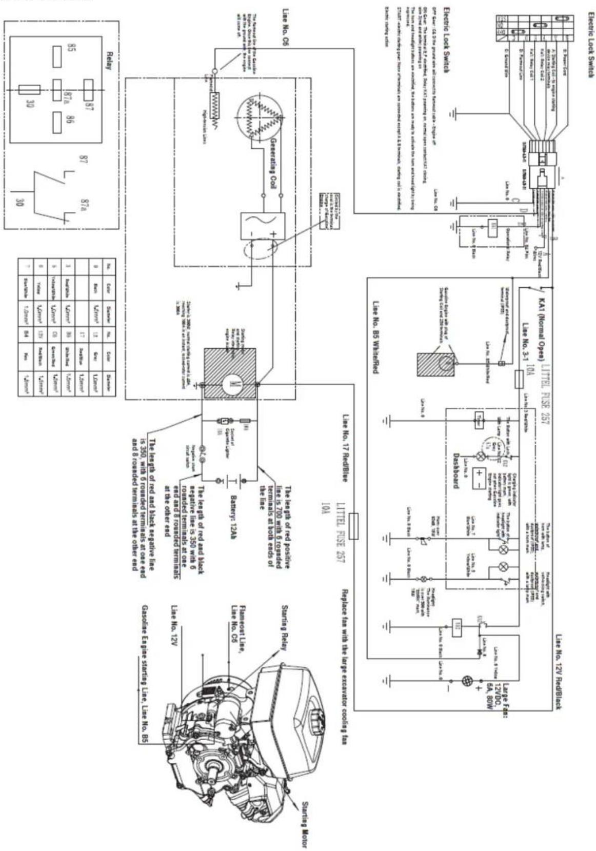
Hydraulic system diagram

flowchart
graph TD
    A["100kV"] --> B["3.836"]
    B --> C["2x2.6mL/T"]
    C --> D["7.015"]
    C --> E["17.5MPa"]
    C --> F["17.5MPa"]
    C --> G["17.5MPa"]
    C --> H["17.5MPa"]
    C --> I["17.5MPa"]
    C --> J["17.5MPa"]
    C --> K["17.5MPa"]
    C --> L["17.5MPa"]
    C --> M["17.5MPa"]
    C --> N["17.5MPa"]
    C --> O["17.5MPa"]
    C --> P["17.5MPa"]
    C --> Q["17.5MPa"]
    C --> R["17.5MPa"]
    C --> S["17.5MPa"]
    C --> T["17.5MPa"]
    C --> U["17.5MPa"]
    C --> V["17.5MPa"]
    C --> W["17.5MPa"]
    C --> X["17.5MPa"]
    C --> Y["17.5MPa"]
    C --> Z["17.5MPa"]
    C --> AA["17.5MPa"]
    C --> AB["17.5MPa"]
    C --> AC["17.5MPa"]
    C --> AD["17.5MPa"]
    C --> AE["17.5MPa"]
    C --> AF["17.5MPa"]
    C --> AG["17.5MPa"]
    C --> AH["17.5MPa"]
    C --> AI["17.5MPa"]
    C --> AJ["17.5MPa"]
    C --> AK["17.5MPa"]
    C --> AL["17.5MPa"]
    C --> AM["17.5MPa"]
    C --> AN["17.5MPa"]
    C --> AO["17.5MPa"]
    C --> AP["17.5MPa"]
    C --> AQ["17.5MPa"]
    C --> AR["17.5MPa"]
    C --> AS["17.5MPa"]
    C --> AT["17.5MPa"]
    C --> AU["17.5MPa"]
    C --> AV["17.5MPa"]
    C --> AW["17.5MPa"]
    C --> AX["17.5MPa"]
    C --> AY["17.5MPa"]
    C --> AZ["17.5MPa"]
    C --> BA["17.5MPa"]
    C --> BB["17.5MPa"]
    C --> BC["17.5MPa"]
    C --> BD["17.5MPa"]
    C --> BE["17.5MPa"]
    C --> BF["17.5MPa"]
    C --> BG["17.5MPa"]
    C --> BH["17.5MPa"]
    C --> BI["17.5MPa"]
    C --> BJ["17.5MPa"]
    C --> BK["17.5MPa"]
    C --> BL["17.5MPa"]
    C --> BM["17.5MPa"]
    C --> BN["17.5MPa"]
    C --> BO["17.5MPa"]
    C --> BP["17.5MPa"]
    C --> BQ["17.5MPa"]
    C --> BR["17.5MPa"]
    C --> BS["17.5MPa"]
    C --> BT["17.5MPa"]
    C --> BU["17.5MPa"]
    C --> BV["17.5MPa"]
    C --> BW["17.5MPa"]
    C --> BX["17.5MPa"]
    C --> BY["17.5MPa"]
    C --> BZ["17.5MPa"]
    C --> CA["17.5MPa"]
    C --> CB["17.5MPa"]
    C --> CC["17.5MPa"]
    C --> CD["17.5MPa"]
    C --> CE["17.5MPa"]
    C --> CF["17.5MPa"]
    C --> CG["17.5MPa"]
    C --> CH["17.5MPa"]
    C --> CI["17.5MPa"]
    C --> CJ["17.5MPa"]
    C --> CK["17.5MPa"]
    C --> CR["17.5MPa"]
    C --> CS["17.5MPa"]
    C --> CT["17.5MPa"]
    C --> CU["17.5MPa"]
    C --> CV["17.5MPa"]
    C --> CW["17.5MPa"]
    C --> CX["17.5MPa"]
    C --> CY["17.5MPa"]
    C --> CZ["17.5MPa"]
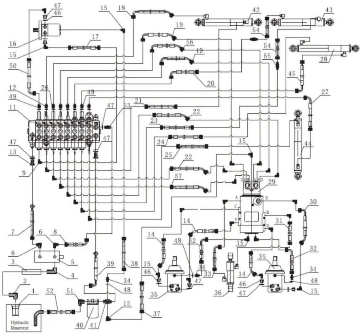
7. OPTIONAL ACCESSORIES
(Sold separately)
The simple construction of these accessories allows a single person to install them on excavators for quick task changes.
With the help of attachments, your excavator can become many additional tools for a wider variety of jobs, making the machine more efficient.
7.1. Pallet nails
The pallet forks are connected to the dozer blade, which can transport, load, and unload various palletized materials.
EN
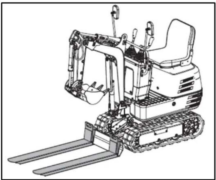
natural_image
Line drawing of an excavator with levers and bucket (no text or symbols)7.1.1. Installing pallet nails
- Stop the machine and lower the bucket to the ground.
- Slightly loosen the M10x40 bolts and nuts attached to the pallet forks.
- Lift the dozer blade slightly and attach the two pallet forks to it.
- Tighten the bolts to secure the connection.
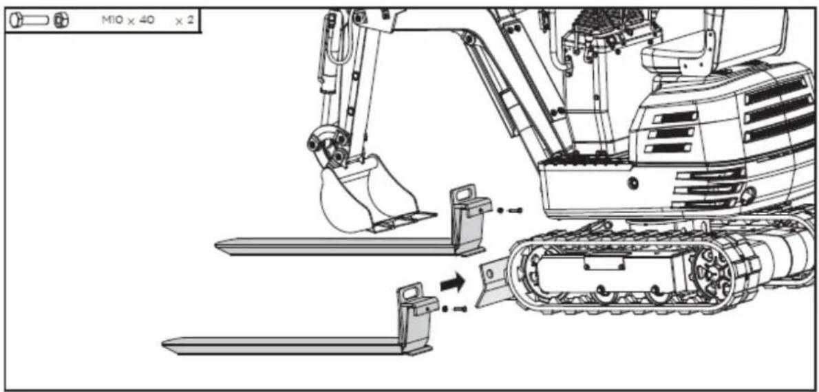
7.2. Rake
The rake is attached to the end of the bucket, making it ideal for collecting straw, sifting waste, or leveling the ground.
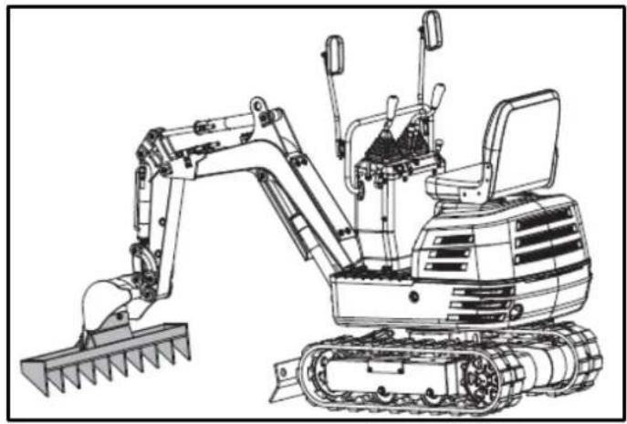
natural_image
Line drawing of an excavator with tracked blade and bucket (no text or symbols)7.2.1. Rake installation
- Stop the machine and raise the bucket off the ground to a specified height.
- Remove the M12x40 bolts, washers, and nuts pre-installed on the rake.
- Mount the rake to the scoop using these standard parts.
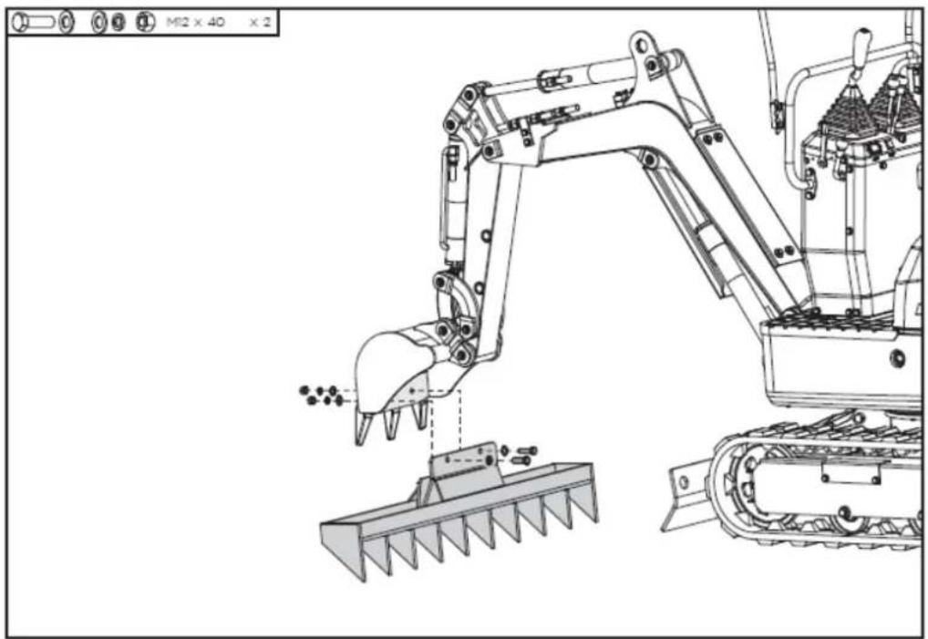
natural_image
Technical line drawing of an excavator and tracked vehicle (no text or symbols)7.3. Additional thumb
The thumb can grip materials in the bucket. It can be used in conjunction with the bucket to grab regularly or irregularly shaped materials, such as rocks, wood, or demolition debris.
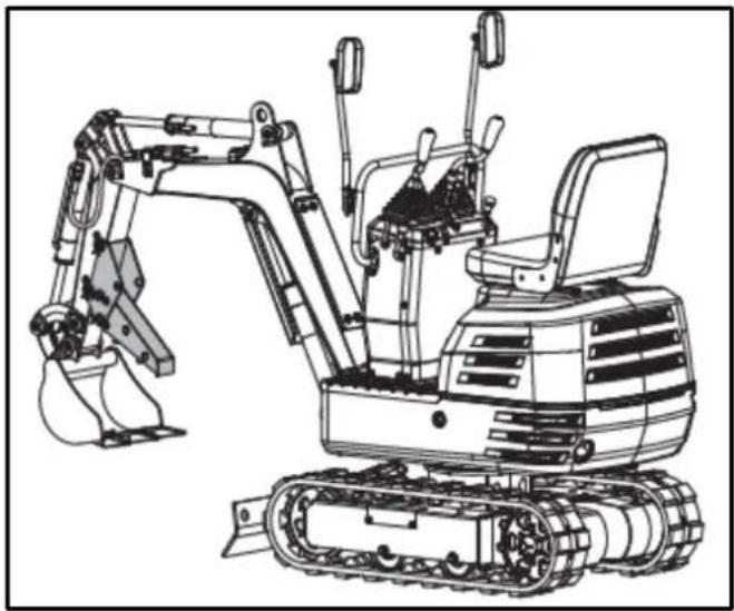
natural_image
Line drawing of an excavator with tracked base and bucket assembly (no text or symbols)7.3.1. Installing the excavator's additional thumb
- Remove the 20x120 pin shafts, washers, and R-pins from the thumb support.
- Attach the bracket to the arm and align the holes.
- Pass two dowel shafts through the holes, place the washers and secure them with the pins at R.
- Insert the larger end of the thumb into the bracket, align the holes, and secure it with the other two pin shafts, washers, and R-pins.
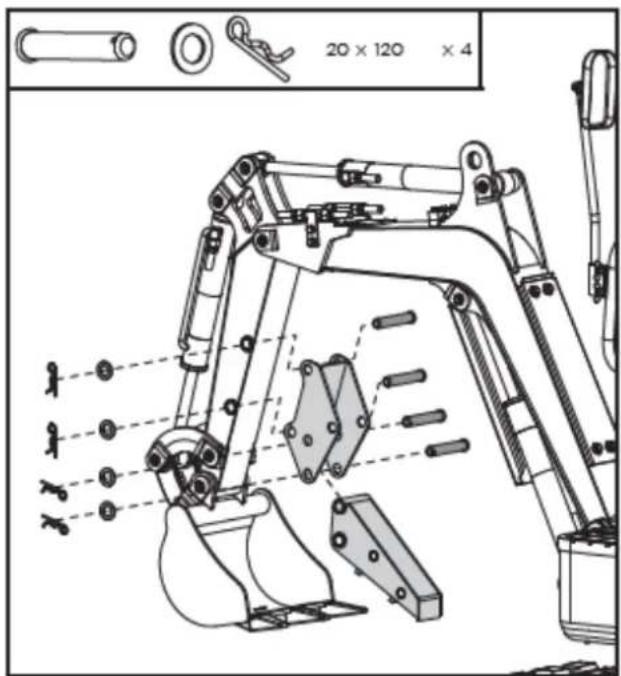
- When not in use, remove the lower R pin and pin shaft, fold the thumb up into the holder and secure it in the upper position with the previously removed parts.
EN
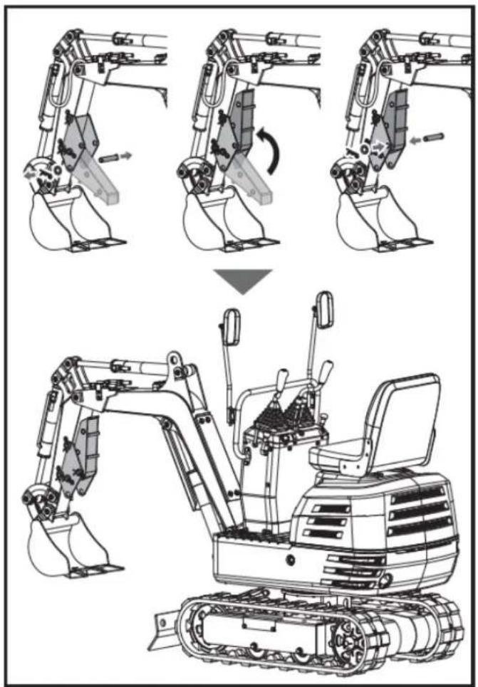
7.4. Claw
The tongs without the cover can be used to collect leaves, gravel, and straw. The tongs with the cover are ideal for small particulate materials, such as sand and soil.
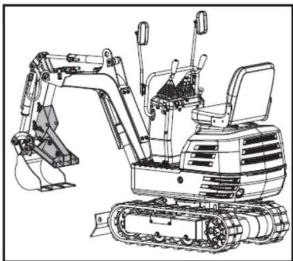
natural_image
Line drawing of an excavator with tracked base and mechanical components (no text or symbols)7.4.1. Claw Installation
- Remove the 16x110 pin shafts, washers, and R-pins from the clamp. Install the clamp on the thumb, align the holes, and secure it with the pin shafts, washers, and R-pins.
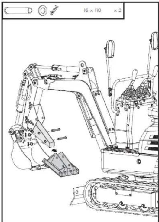
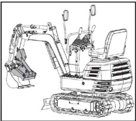
natural_image
Technical line drawing of an excavator with attached mechanical components (no text or symbols)- Remove the 16x300 pin shafts, washers, and R-pins from the claw cover. Attach the cover to the clamp from the outside and align the holes. Pass the 16x300 pin shafts through the holes, position the washers, and secure them with the R-pins.
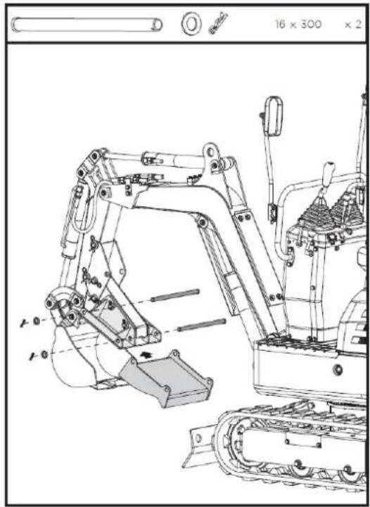
natural_image
Technical line drawing of an excavator assembly (no text or symbols present)7.5. Leveling scoop
The leveling bucket replaces the machine's standard bucket. With its increased capacity, it can double work efficiency when excavating loose materials.
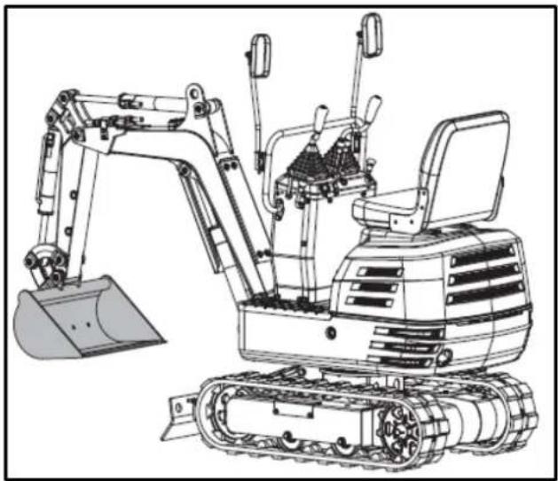
natural_image
Line drawing of an excavator with tracked base and bucket (no text or symbols)7.5.1. Leveling bucket installation
- Stop the machine and place the bucket on the ground.
- Remove the weld from the shovel pin, and then remove the standard scoop from the machine.
- Mount the leveling bucket on the machine with the pins removed in the first step.
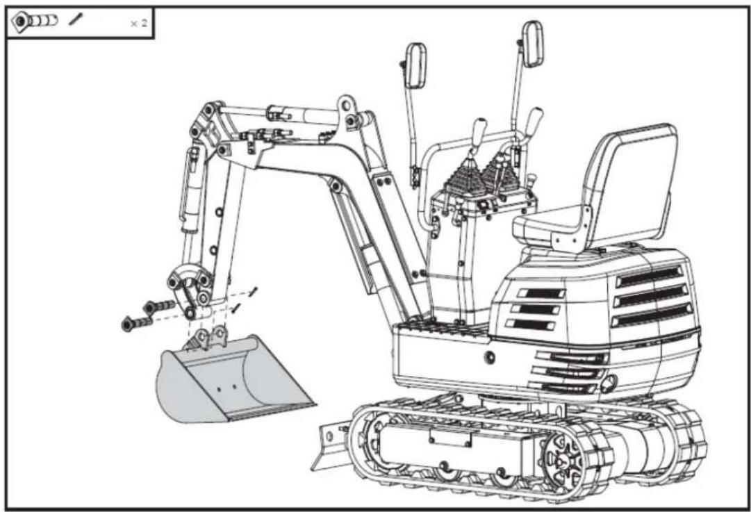
natural_image
Technical line drawing of an excavator with tracked base and bucket, no text or symbols present7.6. Deck
The canopy/cover is attached to the swing unit platform. It's ideal for providing protection from sunlight, rain, and other precipitation. It's easy to install and remove.
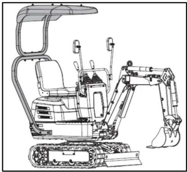
natural_image
Technical line drawing of an excavator with tracked base and attached boom (no text or symbols)7.6.1. Awning installation
- Align the holes in the lower frame of the canopy with the holes in the platform of the swing unit, as shown.
- Secure the lower frame in place using the supplied M10x60 bolts and washers.
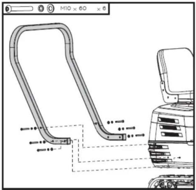
- Align the holes in the top frame with the holes in the bottom frame of the cover, as shown.
- Secure the connection using the supplied M10x95 bolts, washers, and nuts.
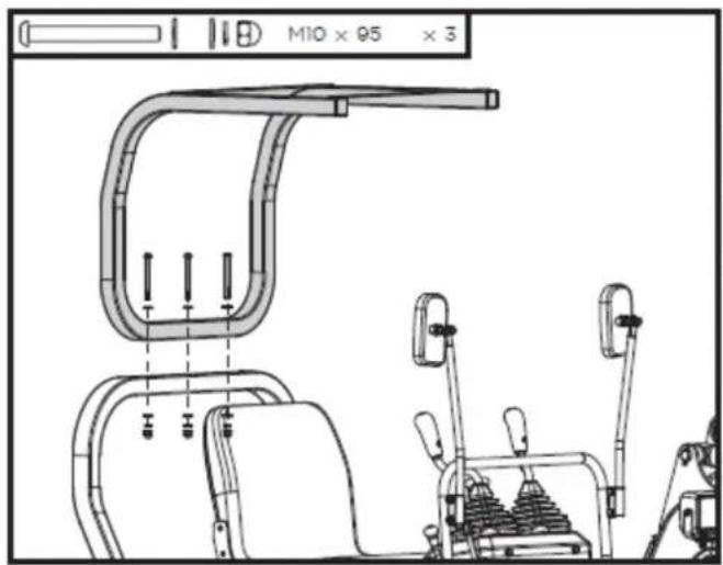
- Align the holes on the top of the awning with the holes in the top frame of the awning, as shown.
- Secure the top of the awning in place using the supplied M8x25 bolts, washers and nuts.
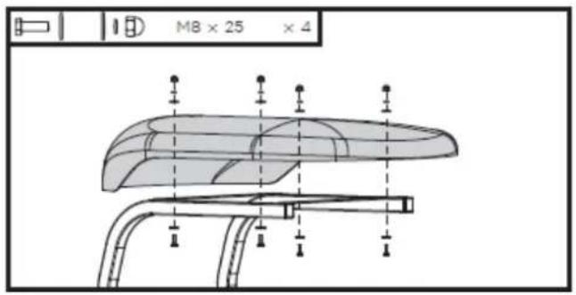
7.7. Ripper Tooth – Excavator Bucket
The excavator bucket is ideal for digging through tough roots, loosening dense soils, and breaking up cracked rocks, making it perfect for confined spaces and complex geology.
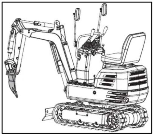
natural_image
Line drawing of an excavator with tracked track and mechanical components (no text or symbols)7.7.1. Excavator bucket installation – Ripper tooth
- Stop the machine and place the bucket on the ground.
- Remove the weld from the shovel pin, and then remove the standard scoop from the machine.
- Mount the Ripper tooth on the machine with the pins removed in the first step.
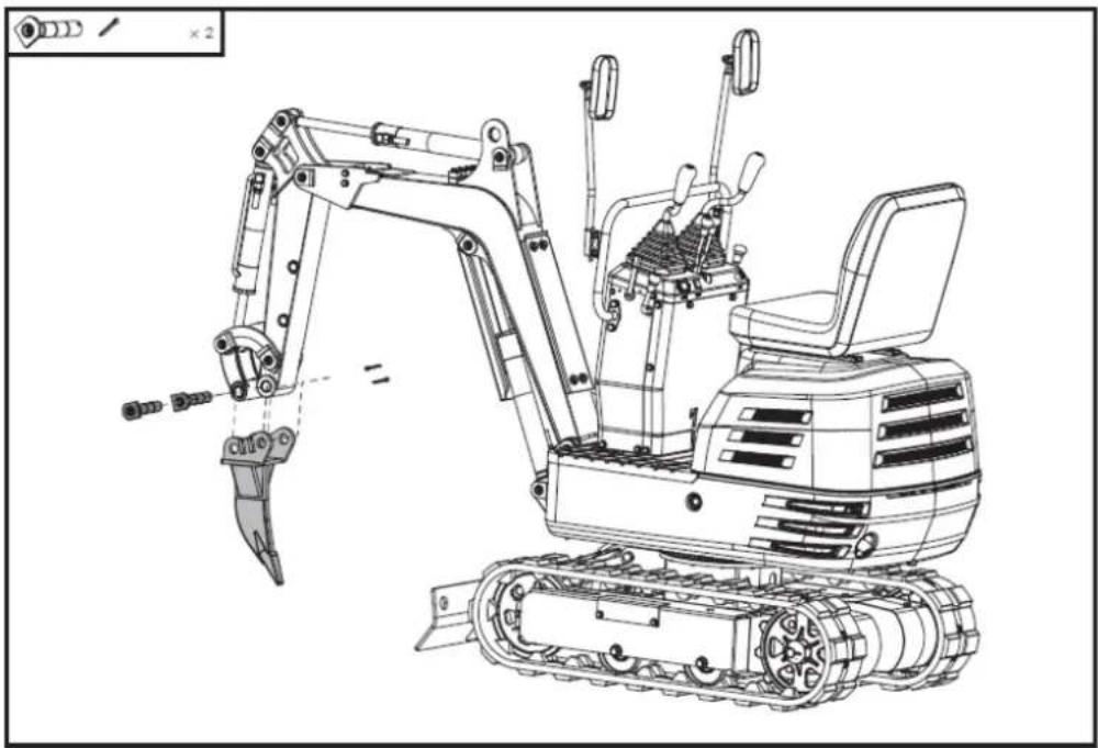
natural_image
Technical line drawing of an excavator with tracked base and attached levers (no text or symbols)8. TROUBLESHOOTING
Warning
Before performing any maintenance, disconnect all controls and stop the engine. Wait until all moving parts have come to a complete stop. Always wear safety glasses during operation or while making adjustments or repairs.
Note: If you cannot resolve the product issues, please contact your official distributor.
| Problem | Possible cause | Solution | |
| Engine | Starting difficulties. | The fuel valve is closed. | Make sure the fuel shut-off valve is in the "Open" position. |
| There is air or water in the fuel system. | Consult the instructions for removing water and air. | ||
| The oil viscosity is too high, so the engine runs slowly in winter. | Use engine oil for winter use. | ||
| The battery is almost dead; the starter motor is not working. | The reverse motion starts to recharge the battery | ||
| The spark plug won't light. | Replace the spark plug. | ||
| Low engine oil level. | Add the engine oil. | ||
| Insufficient engine power. | Low fuel level | Check the fuel and add more if necessary. | |
| Air filter clogged | Clean the air filter element. | ||
| The engine suddenly stops. | Low fuel level. | Check the fuel and add more if necessary.Bleed the fuel system | |
| Abnormal color of exhaust gases | Inadequate fuel. | Use high-quality fuel. | |
| Too much engine oil. | Drain the engine oil to the prescribed level. | ||
| The choke lever closes the choke valve on the carburetor. | Open the choke valve. | ||
| Hydraulic system | The power of the arm, bucket, transmission, swing, and excavator is too low. | Hydraulic oil level too low | Add oil |
| Motor oscillation failure | Leaks in hoses and/or joints | Replace hose or gasket | |
| Transmission system | Deviation from driving direction | Blocked by stones | Withdraw |
| Caterpillars too loose or too tight | Adjust as appropriate | ||
Note: If you have any questions or problems persist after performing the above operations, please contact your official distributor.
Warning
Do not perform any maintenance with the engine running. Ensure you carry out these actions safely. If you have any questions, consult your official Anova dealer.
9. WARRANTY
If your product suffers any manufacturing defect during the established warranty period, please contact or go directly to your point of sale with the necessary documentation.
Your purchase receipt should be kept as proof of the purchase date. Your tool must be returned to your distributor in acceptable and clean condition, in its original molded case, if applicable, along with your corresponding proof of purchase.
9.1. Warranty period
The legal warranty period for the product begins on the original date of purchase by the first initial buyer and its duration will be that established by the Royal Decree-Law on the protection of consumers and users against situations of social and economic vulnerability of the year corresponding to the time of acquisition of the product.
Some countries do not have limitations on how long an implied warranty lasts or do not allow the exclusion or limitation of consequential or incidental damages, in which case the above limitation and exclusion may not apply to you. This warranty gives you specific legal rights, and you may also have other rights that vary from state to state or country to country.
9.2. Exclusions
This warranty does not cover product damage or performance problems caused by:
- Natural wear and tear from use.
- Misuse, negligence, careless operation, or lack of maintenance.
- Defects caused by improper use, damage caused by handling by personnel not authorized by Anova or use of non-original spare parts.
- Defects in normal wear parts, such as bearings, brushes, cables, plugs or accessories such as drills, drill bits, saw blades, etc.
- Damage or defects resulting from abuse, accidents, or alterations.
- Incorrect use and storage (explicit reference to the fact that the rules described in the operating instructions have not been followed).
- Wear and tear caused by the customer (e.g., broken saw blades, consumed carbon brushes, etc.).
- Wear and secondary damage due to lack of maintenance, repair, lubricants (e.g., overheating damage due to blocked cooling slots, bearing damage as a result of dirt, frost damage, etc.)
- Damage as an obvious result of overuse/overload.
- Damage caused by inappropriate supplies (e.g., incorrect fuel)
- Load-induced breakage of housing components or accessories due to abnormal stress
- Load-induced deformation of the housing components or accessories due to abnormal stress.
- Damage resulting from the operation of supplies that are overfilled or leak due to improper storage, improper cleaning agents, or other damaging chemical components.
- Damage due to improper exposure to extreme temperatures (e.g., frost cracking, thermal deformation of components, etc.)
- Damage from permanent exposure to ultraviolet radiation.
- Damage caused by inadequate maintenance.
- Any damage caused by failure to follow the instructions in the instruction manual
EN
- Any product that has been repaired by an unqualified professional.
- Any product connected to an unsuitable power source (amps, voltage, frequency).
- Any damage caused by external influences (water, chemicals, physical, impacts) or foreign substances.
- Use of unsuitable accessories or parts.
- It does not cover defects in normal wear and tear parts, nor does it cover damage or defects resulting from abuse, accidents or alterations, nor transportation costs.
Furthermore, the warranty is voided if the product has been altered or modified, or if the trademark/serial number of the machine has been defaced or removed.
Routine maintenance, tuning, adjustments, or normal wear and tear are not covered under this warranty.
This manual does not cover all possible situations regarding warranty exclusions; for more information, please contact your nearest Anova distributor.
9.3. In case of incident
The warranty must be correctly completed with all the requested information, and accompanied by the purchase invoice.
Anova reserves the right to refuse any claim where the purchase cannot be verified or where it is clear that the product was not properly maintained (maintenance, clean ventilation slots, lubrication, regularly maintained carbon brushes, cleaning, storage, etc.).
Private use is defined as personal domestic use by an end consumer. Commercial use, on the other hand, means all other uses, including uses for business purposes, income generation, or rental. Once the product has been used for commercial purposes, it will be considered a commercial product thereafter for the purposes of this warranty.
These are our standard warranty terms, but occasionally there may be additional warranty coverage not specified at the time of publication. For more information, please contact your nearest authorized Anova dealer or visit www.millasur.com.
Warranty service is only available through authorized Anova distributors. You can find your nearest distributor on our distributor map at www.anova.es.
10. ENVIRONMENT


It is essential to ensure that products and their components are disposed of responsibly to protect the environment. Below, you will find general guidelines for the proper disposal of various materials used in your machine.
Dispose of your machine in an environmentally friendly way. We shouldn't throw machines away with the regular household waste. Their plastic and metal components can be sorted according to their type and recycled.
When disposing of machinery or metal products, it's important to remember that their metal components, such as iron, steel, or aluminum, must be properly recycled at metal recycling facilities. This will contribute to their potential reuse in the manufacture of new products.
Oils and Fuels
Used oils and fuels, among other things, must be recycled properly. Do not pour these liquids down drains, into soil, rivers, lakes, or seas, as they can cause serious environmental damage. Take them to a recycling center or specialized collection point. This process helps prevent water and soil contamination and allows for the safe reuse of oils, if possible.
Plastics
Plastics should be separated and taken to designated recycling points. Do not throw them away with regular household waste. Plastics can be recycled, helping to reduce waste.
Cardboard
Packaging materials, such as cardboard, are recyclable. Be sure to separate clean, dry cardboard and place it in designated recycling containers or at an official waste collection point. Do not dispose of it with household waste.
Batteries
Batteries and other electronic components from machines must be disposed of at designated collection points to prevent the release of toxic substances into the environment. Do not throw them away with regular trash. Take them to appropriate recycling centers for safe and responsible handling.
By following these guidelines, you contribute to environmental protection and resource conservation. For more information on material disposal and recycling, please contact your local authorities and consult the necessary information.
11. EXPLODED VIEW

EN

DISTRIBUTION COMPANY
MILLASUR, SLU
CE DECLARATION OF CONFORMITY
In compliance with the various EC directives, this document confirms that, due to its design and construction, and as indicated by the CE marking affixed by the manufacturer, the machine identified herein meets the relevant and fundamental health and safety requirements of the aforementioned EC directives. This declaration authorizes the product to display the CE marking.
In the event that the machine is modified and this modification is not approved by the manufacturer and communicated to the distributor, this declaration will lose its value and validity.
Machine name: EXCAVATOR
Model: EX650T
Recognized and approved standard to which it conforms:
Directive 2006/42/EC
2000/14/EC
2005/88/EC
Tested according to regulations:
EN 474-1:2022
EN ISO 12100:2010
Company seal
MILLASUR, S.L.U. Rua Eduardo Pondal,23 - Pol.Emp..Sigüeiro 15688-Oroso-A Coruña Tel. (+34) 981 69 64 65 - Fax (+34) 981 69 08 61 e-mail: millasur@millasur.com CIF: B-15 749 922
15/12/2025
Minibagger
EX650T
anova ^10
natural_image
Exterior view of a black and gray ANOVA EHX50T excavator (no signage or text on body)DE
ANOVA®


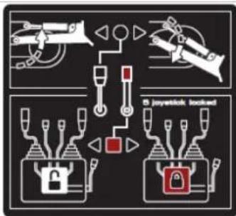
flowchart
graph TD
    A["Device 1"] --> B["Locker"]
    C["Device 2"] --> D["Locker"]
    E["Device 3"] --> F["Locker"]
    G["Device 4"] --> H["Locker"]
    I["Device 5"] --> J["Locker"]
    K["Switch"] --> L["Switch"]
    M["Switch"] --> N["Switch"]
    O["Switch"] --> P["Switch"]
    Q["Switch"] --> R["Switch"]
    S["Switch"] --> T["Switch"]
    U["Switch"] --> V["Switch"]
    W["Switch"] --> X["Switch"]
    Y["Switch"] --> Z["Switch"]
    AA["Switch"] --> AB["Switch"]
    AC["Switch"] --> AD["Switch"]
    AE["Switch"] --> AF["Switch"]
    AG["Switch"] --> AH["Switch"]
    AI["Switch"] --> AJ["Switch"]
    AK["Switch"] --> AL["Switch"]
    AM["Switch"] --> AN["Switch"]
    AO["Switch"] --> AP["Switch"]
    AQ["Switch"] --> AR["Switch"]
    AS["Switch"] --> AT["Switch"]
    AU["Switch"] --> AV["Switch"]
    AW["Switch"] --> AX["Switch"]
    AY["Switch"] --> AZ["Switch"]
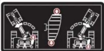
natural_image
Three identical diagrams showing mechanical or electrical components with no visible text, numbers, or symbols.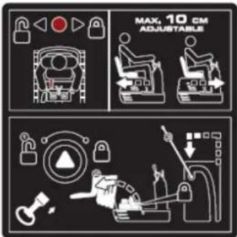
natural_image
Illustration of a magnifying glass examining a document with a hand holding it, symbolizing search or review (no text present)Manuelles Rohr

natural_image
Line drawing of an excavator on a utility pole with power lines and a sunburst in the background (no text or symbols)natural_image
Technical line drawing of an excavator on a construction site (no text or symbols)natural_image
Technical line drawing of a vehicle chassis with labeled sections A and B (no text or symbols on the diagram itself)natural_image
Technical line drawing of an excavator with attached equipment, shown in side profile (no text or symbols)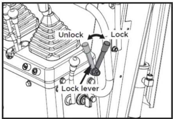
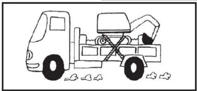
natural_image
Line drawing of a dump truck with an excavator and bucket, parked near debris (no text or symbols)1
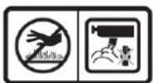
2
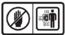
3
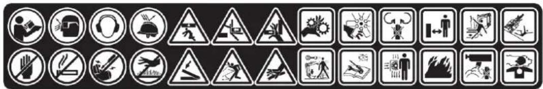
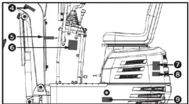
4
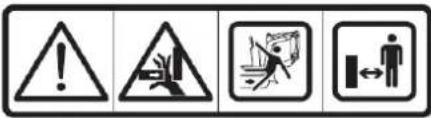
5
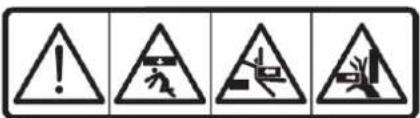
6
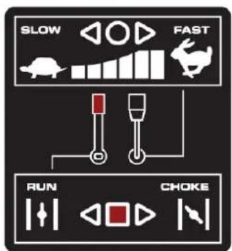
7
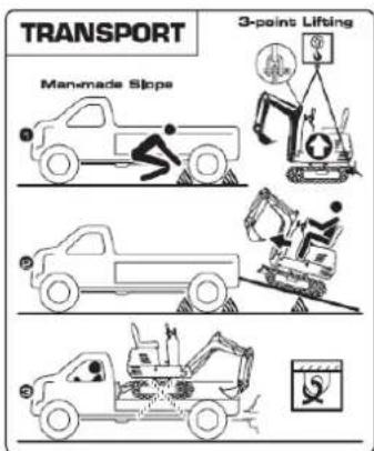
8
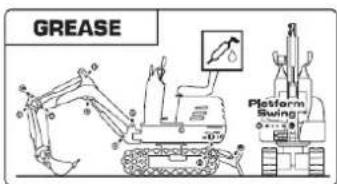
9

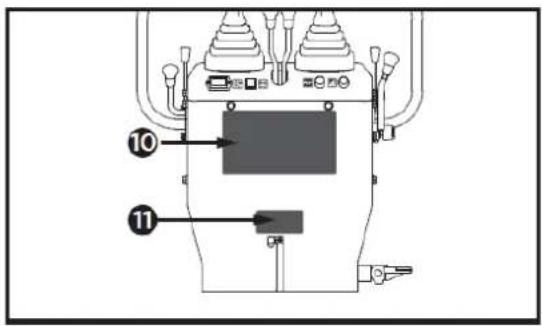
10

flowchart
graph TD
    A["Robot"] --> B["Control Unit"]
    C["Robot"] --> D["Control Unit"]
    E["Robot"] --> F["Control Unit"]
    G["Robot"] --> H["Control Unit"]
    I["Robot"] --> J["Control Unit"]
    K["Robot"] --> L["Control Unit"]
    M["Robot"] --> N["Control Unit"]
    O["Robot"] --> P["Control Unit"]
    Q["Robot"] --> R["Control Unit"]
    S["Robot"] --> T["Control Unit"]
    U["Robot"] --> V["Control Unit"]
    W["Robot"] --> X["Control Unit"]
    Y["Robot"] --> Z["Control Unit"]
    AA["Robot"] --> AB["Control Unit"]
    AC["Robot"] --> AD["Control Unit"]
    AE["Robot"] --> AF["Control Unit"]
    AG["Robot"] --> AH["Control Unit"]
    AI["Robot"] --> AJ["Control Unit"]
    AK["Robot"] --> AL["Control Unit"]
    AM["Robot"] --> AN["Control Unit"]
    AO["Robot"] --> AP["Control Unit"]
    AQ["Robot"] --> AR["Control Unit"]
    AS["Robot"] --> AT["Control Unit"]
    AU["Robot"] --> AV["Control Unit"]
    AW["Robot"] --> AX["Control Unit"]
    AY["Robot"] --> AZ["Control Unit"]
    BA["Robot"] --> BB["Control Unit"]
    BC["Robot"] --> BD["Control Unit"]
    BE["Robot"] --> BF["Control Unit"]
    BG["Robot"] --> BH["Control Unit"]
    BI["Robot"] --> BJ["Control Unit"]
    BK["Robot"] --> BL["Control Unit"]
    BM["Robot"] --> BN["Control Unit"]
    BO["Robot"] --> BP["Control Unit"]
    BQ["Robot"] --> BR["Control Unit"]
    BS["Robot"] --> BT["Control Unit"]
    BU["Robot"] --> BV["Control Unit"]
    BW["Robot"] --> BX["Control Unit"]
    BY["Robot"] --> BZ["Control Unit"]
    CA["Robot"] --> CB["Control Unit"]
    CC["Robot"] --> CD["Control Unit"]
    CE["Robot"] --> CF["Control Unit"]
    DG["Robot"] --> DH["Control Unit"]
    DI["Robot"] --> DJ["Control Unit"]
    DK["Robot"] --> DL["Control Unit"]
    DM["Robot"] --> DE["Control Unit"]
    DF["Robot"] --> DG
    DG --> DG
    DG --> DG
    DG --> DG
    DG --> DG
    DG --> DG
    DG --> DG
    DG --> DG
    DG --> DG
    DG --> DG
    DG --> DG
    DG --> DG
    DG --> DG
    DG --> DG
    DG --> DG
    DG --> DG
    DG --> DG
    DG --> DG
    DG --> DG
    DG --> DG
    DG --> DG
    DN["Robot"] --> DN
    DN --> DN
    DN --> DN
    DN --> DN
    DN --> DN
    DN --> DN
    DN --> DN
    DN --> DN
    DN --> DN
    DN --> DN
    DN --> DN
    DN --> DN
    DN --> DN
    DN --> DN
    DN --> DN
    DN --> DN
    DN --> DN
    DN --> DN
    DN --> DN
    DN --> DN
    DN --> DN
    BN["Robot"] --> BO
    BO --> BC
    BO --> DC
    BO --> DT
    BO --> DU
    BO --> DV
    BO --> DW
    BO --> DX
    BO --> DXD
    BO --> DXD
    BO --> DXD
    BO --> DXD
    BO --> DXD
    BO --> DXD
    BO --> DXD
    BO --> DXD
    BO --> DXD
    BO --> DXD
    BO --> DXD
    BO --> DXD
    BO --> DXD
11

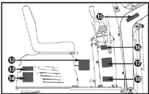
12

13
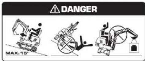
17
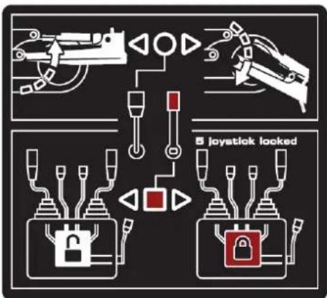
14

18
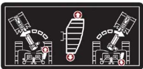
natural_image
Three identical diagrams showing a spacecraft and a ground vehicle with red warning symbols, no text or labels present.15

16

4.2. Montage
natural_image
Technical line drawing of a vehicle seat assembly showing front and side views (no text or symbols)natural_image
Technical line drawing of a mechanical device with labeled component A (no text or symbols beyond label)A: Hupenschalter
Wichtig
natural_image
Technical line drawing of a mechanical assembly with labeled components (no readable text or symbols)A. Betriebsanzeige
natural_image
Technical line drawing of a mechanical assembly with labeled component A (no text or symbols beyond label)natural_image
Technical line drawing of a mechanical assembly with no visible text or symbolsnatural_image
Technical diagram of a piping system with valve and valve components (no text or labels)
natural_image
Technical line drawing of an excavator assembly with no visible text or symbolsWichtig
natural_image
Technical diagram of a mechanical or electrical component with pipe connections and a highlighted section showing a downward arrow (no text or symbols present)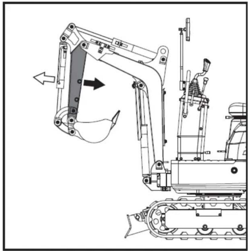
natural_image
Technical line drawing of an excavator and tracked vehicle (no text or symbols)natural_image
Technical line drawing of a piping system with valves and a valve (no text or labels)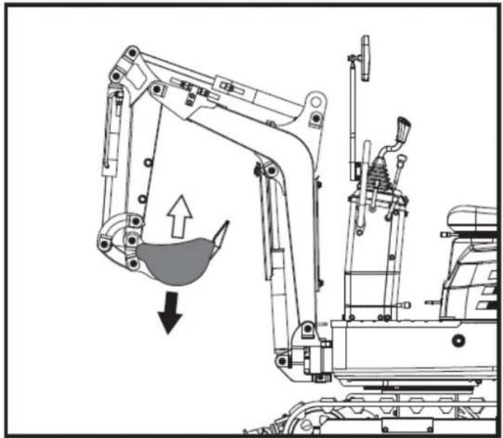
natural_image
Technical line drawing of an excavator with a downward load arrow, showing mechanical components without any text or symbols.natural_image
Technical diagram of a heat exchanger or cooling unit with piping and fan components (no text or labels)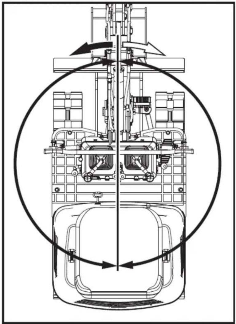
natural_image
Technical line drawing of a mechanical assembly with no visible text or symbolsnatural_image
Technical line drawing of a mechanical device with no visible text or symbols
natural_image
Technical diagram of a mechanical assembly with directional arrows indicating motion (no text or labels)natural_image
Technical line drawing of an excavator and tracked vehicle (no text or symbols)natural_image
Technical line drawing of two excavators with directional arrows indicating movement (no text or symbols)Wichtig
natural_image
Line drawing of a bulldozer with a cross symbol crossed out, no text or symbols present5.5.2. Kurven
Wichtig
natural_image
Technical diagram showing a mechanical assembly with an upward arrow and a side-view view of a tracked vehicle (no text or symbols present)DE
A. Links abbiegen
B. Linksabbiegen

natural_image
Line drawing of an excavator on a construction ground (no text or symbols)natural_image
Technical line drawing of an excavator on a sloped terrain, labeled with point A (no text or symbols beyond label)A. Keil
natural_image
Line drawing of an excavator on a dump truck, no text or symbols presentGefahr
natural_image
Illustration of a worker digging into a pile with an upward arrow, next to a dump truck (no text or symbols)DE
natural_image
Line drawing of a flatbed truck with an excavator on an inclined ramp (no text or symbols)natural_image
Cartoon illustration of a front-end loader dumping material into a pile of waste (no text or symbols)natural_image
Technical line drawing of a tracked excavator with labeled component A (no text or symbols beyond label)A. Schäkel
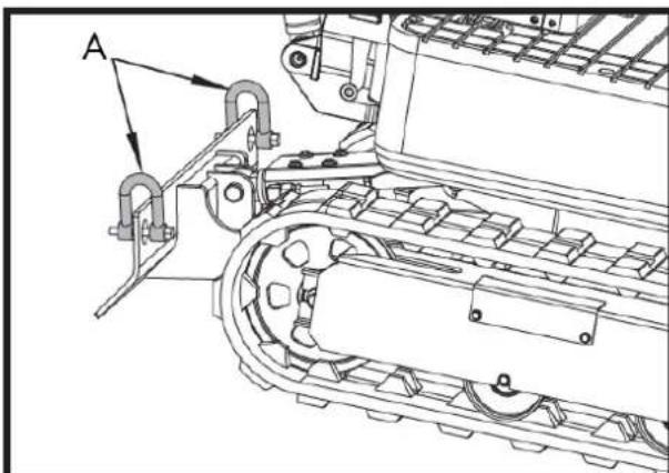
natural_image
Technical line drawing of a mechanical assembly with labeled component A (no text or symbols beyond label)A. Schäkel
DE
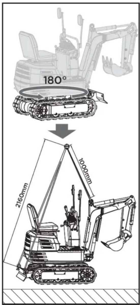
6. WARTUNG
natural_image
Technical line drawing of a mechanical assembly with labeled component A (no text or symbols beyond label)A. Tankdeckel
natural_image
Technical line drawing of a mechanical assembly with labeled component A (no text or symbols beyond label)A. Lüftungsöffnung
natural_image
Technical line drawing of an electric motor assembly with labeled components (no text or symbols present)natural_image
Technical line drawing of a tank interior showing engine, chassis, and structural components (no text or labels)natural_image
Technical line drawing of a tracked vehicle with visible tracks and structural components (no text or symbols)
natural_image
Technical line drawing of a mechanical assembly with labeled component A (no text or symbols beyond label)natural_image
Technical line drawing of a tracked vehicle with labeled component 'A' (no text or symbols beyond label)natural_image
Silhouette of a human head with an eyepatch and motion arrows indicating motion (no text or symbols)Druckluftreinigung
natural_image
Illustration of a hand using a tool to mark a textured surface with diagonal lines (no text or symbols)Wichtig
natural_image
Technical line drawing of a vehicle engine bay with labeled component 'A' (no text or symbols beyond label)Zündkerzenwartung
natural_image
Technical line drawing of a tracked vehicle with labeled component A (no text or symbols beyond label)A. Fettpresse
natural_image
Technical line drawing of a tracked vehicle with labeled component A (no text or symbols beyond label)A. Saugfilter
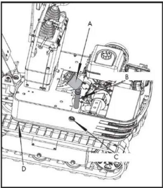
natural_image
Technical line drawing of a tracked vehicle with labeled component A (no text or symbols beyond label)A. Ablassschraube
A. M20x120 Schraube
B. M20 Mutter
C. 30 mm verstellbarer
Schraubenschlüssel
natural_image
Technical line drawing of an excavator with attached boom and levers (no text or symbols)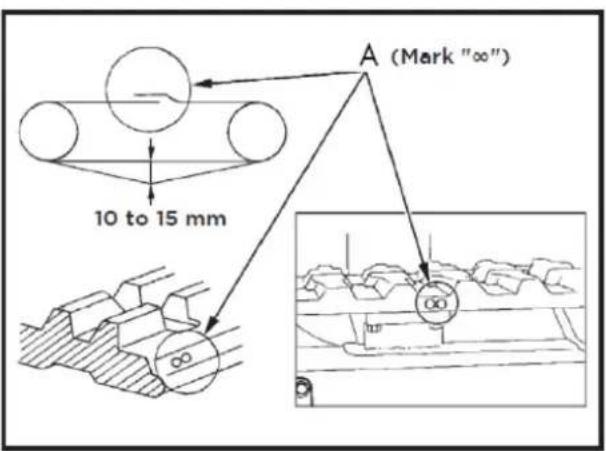
A. Union
Wichtig
natural_image
Technical line drawing of a mechanical assembly with labeled components (A and B), showing internal components and assembly details without any readable text or symbols.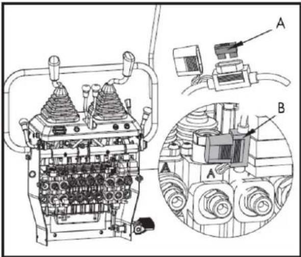
natural_image
Line drawing of a tracked excavator with levers and bucket (no text or symbols)7.2. Rechen
natural_image
Line drawing of an excavator with tracked blade and bucket (no text or symbols)7.2.1. Recheninstallation
natural_image
Technical line drawing of an excavator and tracked vehicle (no text or symbols)natural_image
Line drawing of an excavator with tracked base and bucket (no text or symbols)7.4. Klaue
natural_image
Line drawing of an excavator with tracked base and mechanical components (no text or symbols)7.4.1. Krallenmontage
natural_image
Line drawing of an excavator with attached mechanical components (no text or symbols)natural_image
Technical line drawing of an excavator assembly (no text or symbols present)natural_image
Line drawing of an excavator with tracked base and blade assembly (no text or symbols)7.5.1. Nivellierschaufel-Montage
natural_image
Technical line drawing of an excavator with tracked base and bucket, no text or symbols present7.6. Deck
natural_image
Technical line drawing of an excavator with attached tracks and levers (no text or symbols)7.6.1. Markisenmontage
natural_image
Line drawing of an excavator with tracked track and attached gear (no text or symbols)natural_image
Technical line drawing of an excavator with tracked base and attached levers (no text or symbols)8. FEHLERBEHEBUNG
⚠ Warning
DE

12. CE-ZERTIFIKAT
natural_image
Exterior view of a black and gray DNOVA EX6SOT excavator with tracked tracks (no visible text or symbols on the device body)NL
ANOVA®
2. PRODUCTBESCHRIJVING
7. OPTIONELE ACCESSOIRES
8. PROBLEEMOPLOSSING
9. GARANTIE
10.OMGEVING
11. ONDERDELENOVERZICHT
12.CE-CERTIFICAAT
1. VEILIGHEIDSINSTRUCTIES


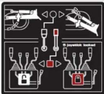
flowchart
graph TD
    A["Fire"] --> B["Lock"]
    B --> C["Fire Shield"]
    C --> D["Fire Alert"]
    D --> E["Fire Alert"]
    style A fill:#f9f,stroke:#333
    style B fill:#ccf,stroke:#333
    style C fill:#cfc,stroke:#333
    style D fill:#fcc,stroke:#333
    style E fill:#ffc,stroke:#333
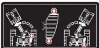
natural_image
Three identical diagrams showing mechanical or robotic components with no visible text, numbers, or symbols.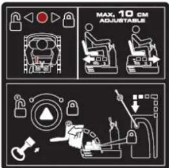
12V, 15A stopcontact
MOTOR AAN/UIT/START SCHAKELAAR
natural_image
Illustration of a hand holding a smartphone with magnifying glass examining a device (no text or symbols)Handmatige buis
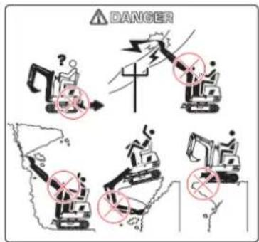
Smeer de graafmachine regelmatig in.
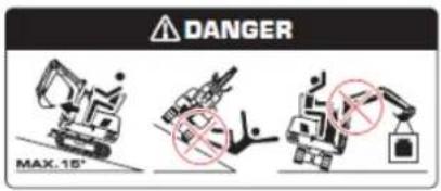
Voorkom dat de machine omvalt.
natural_image
Line drawing of an excavator performing maintenance on power lines (no text or symbols)natural_image
Technical line drawing of an excavator on a construction site (no text or symbols)natural_image
Technical line drawing of a vehicle chassis with labeled sections A and B (no text or symbols on the diagram itself)natural_image
Technical line drawing of an excavator with attached equipment, shown in side profile (no text or symbols)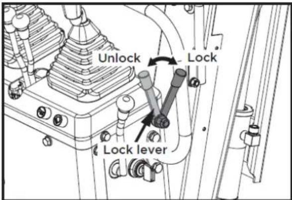
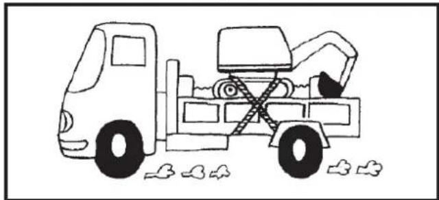
natural_image
Simple line drawing of a dump truck with a bucket and load, no text or symbols present1
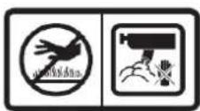
2
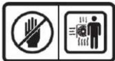
3
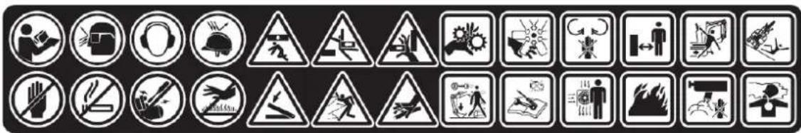
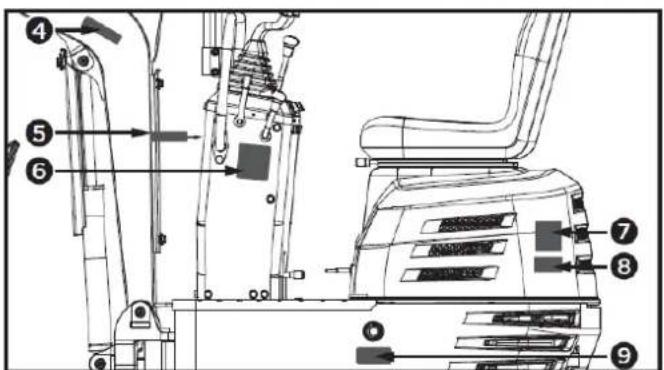
4
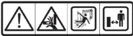
5
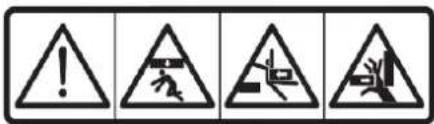
6
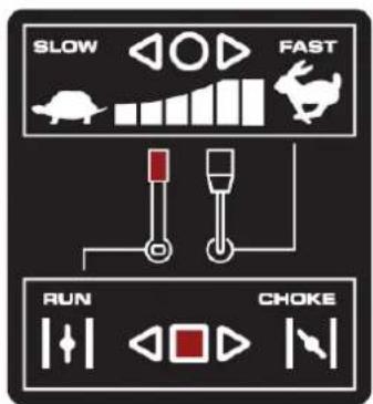
7
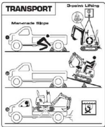
8
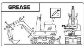
9


10
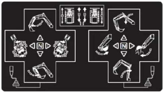
flowchart
graph TD
    A["Robot Arm"] --> B["Control Panel"]
    C["Tractor Arm"] --> D["Control Panel"]
    E["Robot Arm"] --> F["Control Panel"]
    G["Tractor Arm"] --> H["Control Panel"]
    I["Robot Arm"] --> J["Control Panel"]
    K["Tractor Arm"] --> L["Control Panel"]
    M["Robot Arm"] --> N["Control Panel"]
    O["Tractor Arm"] --> P["Control Panel"]
    Q["Robot Arm"] --> R["Control Panel"]
    S["Tractor Arm"] --> T["Control Panel"]
    U["Robot Arm"] --> V["Control Panel"]
    W["Tractor Arm"] --> X["Control Panel"]
    Y["Robot Arm"] --> Z["Control Panel"]
11


12

13

17

14
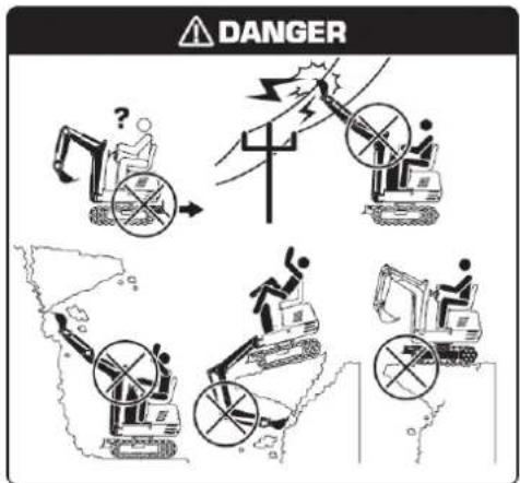
18

natural_image
Three identical diagrams showing a spacecraft and a ground vehicle with red warning symbols, no text or labels present.15

16

2. PRODUCTBESCHRIJVING
2.1. Machineonderdelen
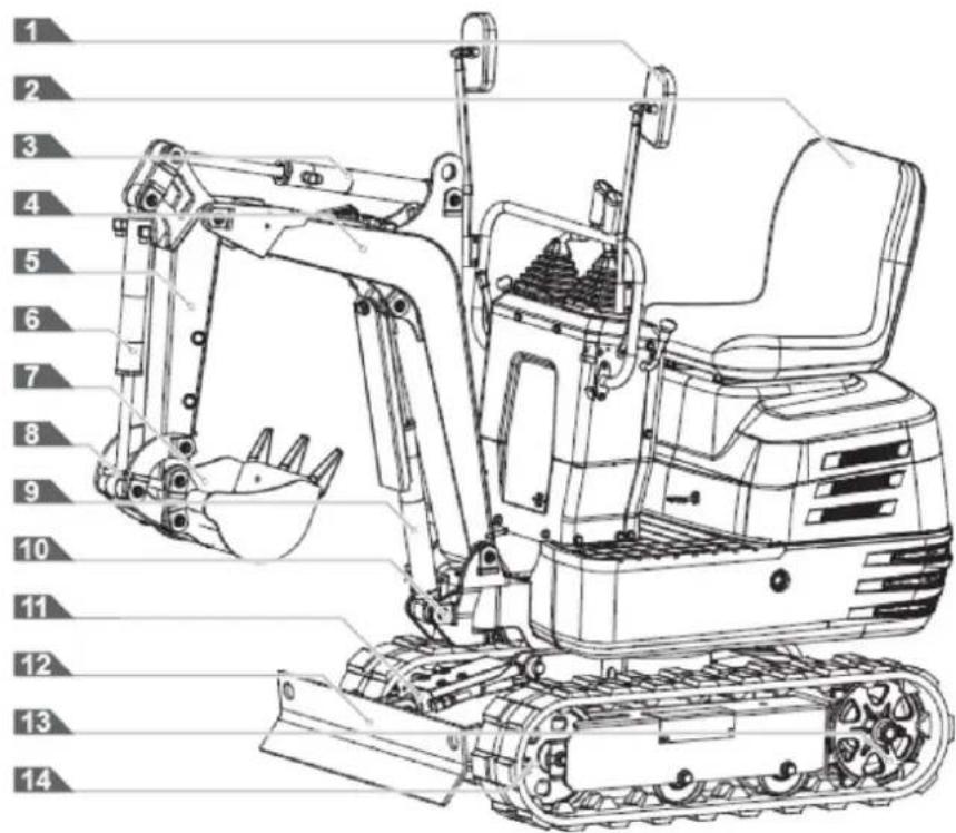
4.2. Montage
natural_image
Technical line drawing of a vehicle's seat assembly and maintenance mechanism (no text or symbols)Draaibare vergrendelingspen
natural_image
Technical line drawing of a mechanical device with labeled component A (no text or symbols beyond label)A: Claxonschakelaar
Belangrijk
natural_image
Technical line drawing of a mechanical device with labeled components (no readable text or symbols)A. Stroomindicator
natural_image
Technical line drawing of a mechanical device with labeled component A (no text or symbols beyond label)A. Urenteller
natural_image
Technical line drawing of a mechanical assembly with no visible text or symbolsWerklichtschakelaar
natural_image
Technical diagram of a piping system with valve and valve components (no text or labels)
natural_image
Technical line drawing of an excavator assembly with no visible text or symbolsBelangrijk
natural_image
Technical diagram of a mechanical or electrical component with pipe connections and a highlighted section showing a downward arrow (no text or symbols present)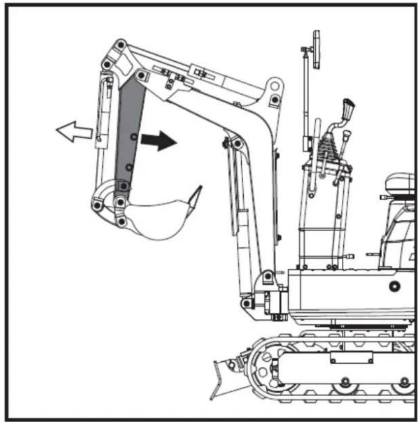
natural_image
Technical line drawing of a tracked excavator with attached mechanical components (no text or symbols)natural_image
Technical diagram of a piping system with valves and valves, showing internal components and directional arrows (no text or labels)
natural_image
Technical line drawing of an excavator with a downward load arrow, showing mechanical components without any text or symbols.natural_image
Technical diagram of a mechanical or industrial system with pipes and a central component, no visible text or symbols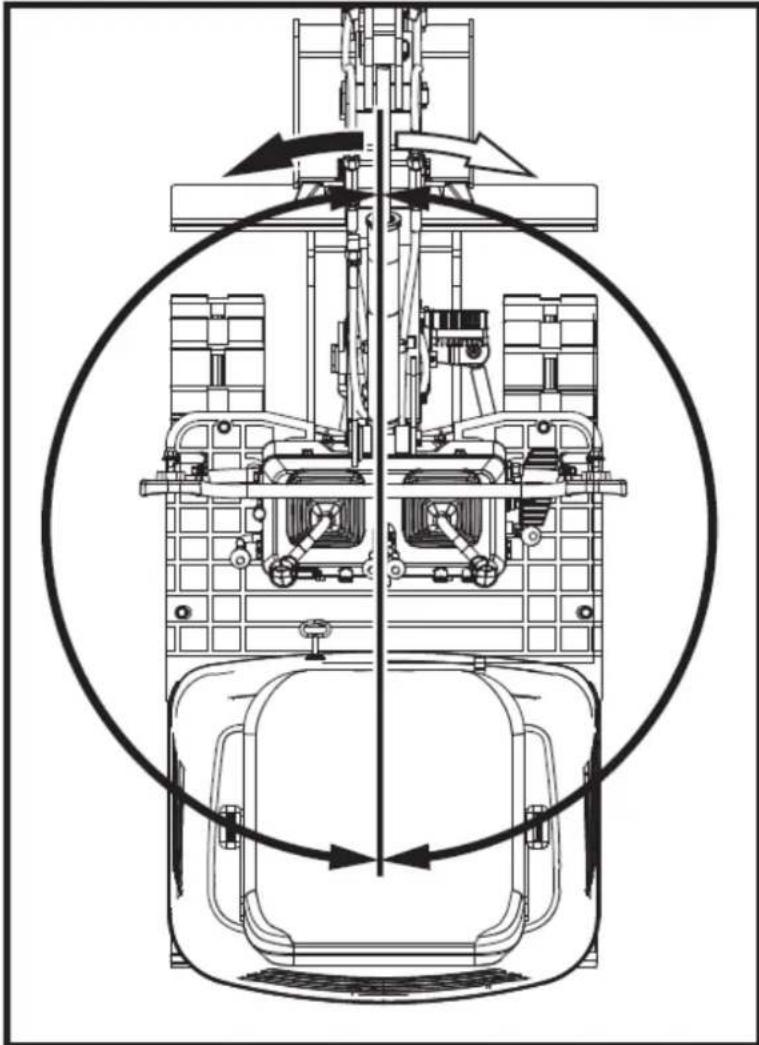
natural_image
Technical line drawing of a mechanical assembly with no visible text or symbols5.4.10. Giekrotatie
natural_image
Technical line drawing of a mechanical device with no visible text or symbols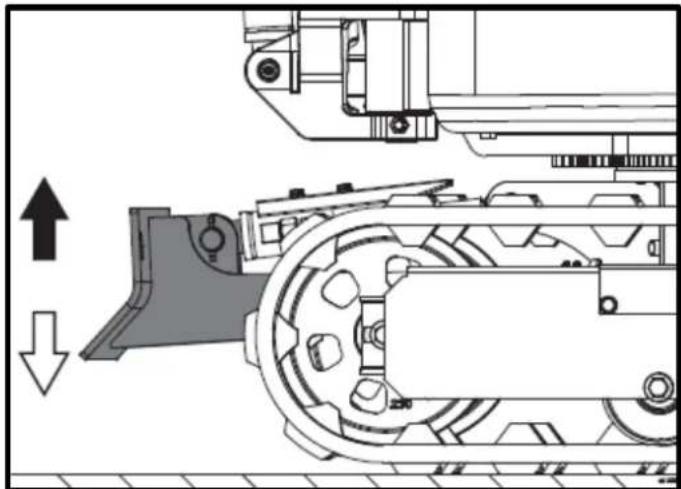
natural_image
Technical diagram of a mechanical assembly with directional arrows indicating movement (no text or symbols)natural_image
Technical line drawing of a tracked excavator with labeled component A, showing mechanical assembly and support structure (no text or symbols beyond labels)natural_image
Technical line drawing of two excavators with directional arrows indicating movement (no text or symbols)Belangrijk
natural_image
Line drawing of a bulldozer with a cross symbol crossed out, no text or symbols present5.5.2. Draait
Belangrijk
natural_image
Technical diagram showing a mechanical assembly with an upward arrow and a side-view view of a tracked vehicle (no text or symbols present)A. Linksaf slaan
B. Linksaf slaan
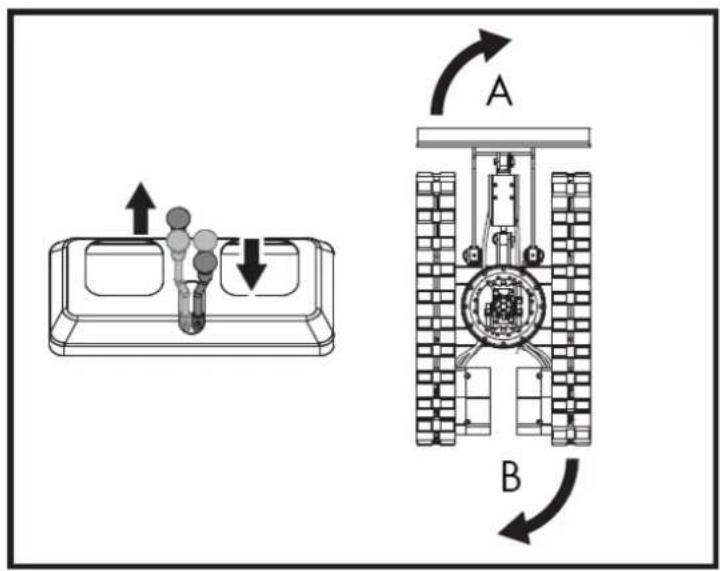
natural_image
Line drawing of an excavator on a construction ground (no text or symbols)natural_image
Technical line drawing of an excavator on a sloped terrain, labeled with point A (no text or symbols beyond label)A. Wig
natural_image
Line drawing of an excavator on a dump truck, no text or symbols presentGevaar
natural_image
Illustration of a worker pushing a dump truck with an upward arrow indicating load or damage (no text or symbols)NL
natural_image
Line drawing of an excavator on a flatbed truck, no text or symbols presentA. Draaibare borgpen.
B. Ontgrendelen.
C-blok.
natural_image
Simple line drawing of a front-end loader dumping material into a truck (no text or symbols)natural_image
Technical line drawing of a tracked excavator with labeled component A (no text or symbols beyond label)A. Ketenen
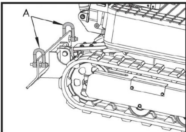
natural_image
Technical line drawing of a tracked vehicle with labeled component A (no text or symbols beyond label)A. Ketenen
NL

6. ONDERHOUD
natural_image
Technical line drawing of a mechanical assembly with labeled component A (no text or symbols beyond label)A. Tankdop
natural_image
Technical line drawing of a mechanical assembly with labeled component A (no readable text or symbols)natural_image
Technical line drawing of an electric motor assembly with labeled components (no text or symbols present)natural_image
Technical line drawing of a tank interior showing engine, chassis, and structural components (no text or labels)A. Ventilatie van de carburateur
A. Olie-indicator
B. Gat vullen
Belangrijk
natural_image
Technical line drawing of a tracked vehicle with visible tracks and structural components (no text or symbols)
natural_image
Technical line drawing of a mechanical assembly with labeled component A (no text or symbols beyond label)natural_image
Technical line drawing of a tracked vehicle with labeled component 'A' (no text or symbols beyond label)A. Bevestigingsbout
B. Luchtfilterkap
C. Luchtfilterelement
D. Luchtfilterzitting
natural_image
Silhouette of a human head with an eyepatch and motion arrows indicating speed or pressure (no text or symbols)natural_image
Line drawing of a hand holding a pen over a rectangular object with diagonal stripes (no text or symbols)Belangrijk
natural_image
Technical line drawing of a vehicle engine bay with labeled components (no text or symbols present)natural_image
Technical line drawing of a tracked vehicle with labeled components (no text or symbols present)A. Vetsput
6.3.3. Elke 200 uur dienstverlening
A. Bevestigingsbout
B. Luchtfilterkap
C. Luchtfilterelement
D. Luchtfilterzitting
⚠️ Voorzichtigheid
natural_image
Technical line drawing of a tracked vehicle with labeled component A (no text or symbols beyond label)A. Zuigfilter
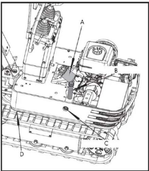
natural_image
Technical line drawing of a tracked vehicle with labeled component A (no text or symbols beyond label)A. Aftapplug
A. M20x120 schroef
B. M20 Moer
C. 30 mm verstelbare sleutel
natural_image
Technical line drawing of an excavator with tracked arm and base mount (no text or symbols)
A. Unie
Belangrijk
natural_image
Technical line drawing of an automotive engine assembly with labeled components (A and B), showing internal components and wiring (no text or symbols beyond labels)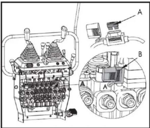
B. Zekeringkast
7. OPTIONELE ACCESSOIRES
natural_image
Line drawing of an excavator with levers and bucket (no text or symbols)7.1.1. Palletnagels installeren
7.2. Hark
natural_image
Technical line drawing of an excavator with tracked blade and bucket (no text or symbols)7.2.1. harkinstallatie
natural_image
Technical line drawing of an excavator and tracked vehicle (no text or symbols)7.3. Extra duim
natural_image
Line drawing of an excavator with tracked base and bucket (no text or symbols)7.4. Klauw
natural_image
Line drawing of an excavator with tracked base and mechanical components (no text or symbols)natural_image
Technical line drawing of an excavator with attached mechanical components (no text or symbols)natural_image
Technical line drawing of an excavator assembly (no text or symbols present)7.5. Nivelleerschep
natural_image
Line drawing of an excavator with tracked base and bucket (no text or symbols)natural_image
Technical line drawing of an excavator with tracked base and bucket (no text or symbols)7.6. Dek
natural_image
Technical line drawing of an excavator with attached tracks and levers (no text or symbols)7.6.1. Luifelinstallatie
natural_image
Line drawing of an excavator with tracked track and blade assembly (no text or symbols)natural_image
Technical line drawing of an excavator with tracked base and attached levers (no text or symbols)8. PROBLEEMOPLOSSING
⚠ Waarschuwing
NL

12. CE-CERTIFICAAT
DISTRIBUTIEBEDRIJF
MILLASUR, SLU