WM106BI - Basket Atag - Free user manual and instructions
Find the device manual for free WM106BI Atag in PDF.

User questions about WM106BI Atag
0 question about this device. Answer the ones you know or ask your own.
Ask a new question about this device
Download the instructions for your Basket in PDF format for free! Find your manual WM106BI - Atag and take your electronic device back in hand. On this page are published all the documents necessary for the use of your device. WM106BI by Atag.
USER MANUAL WM106BI Atag
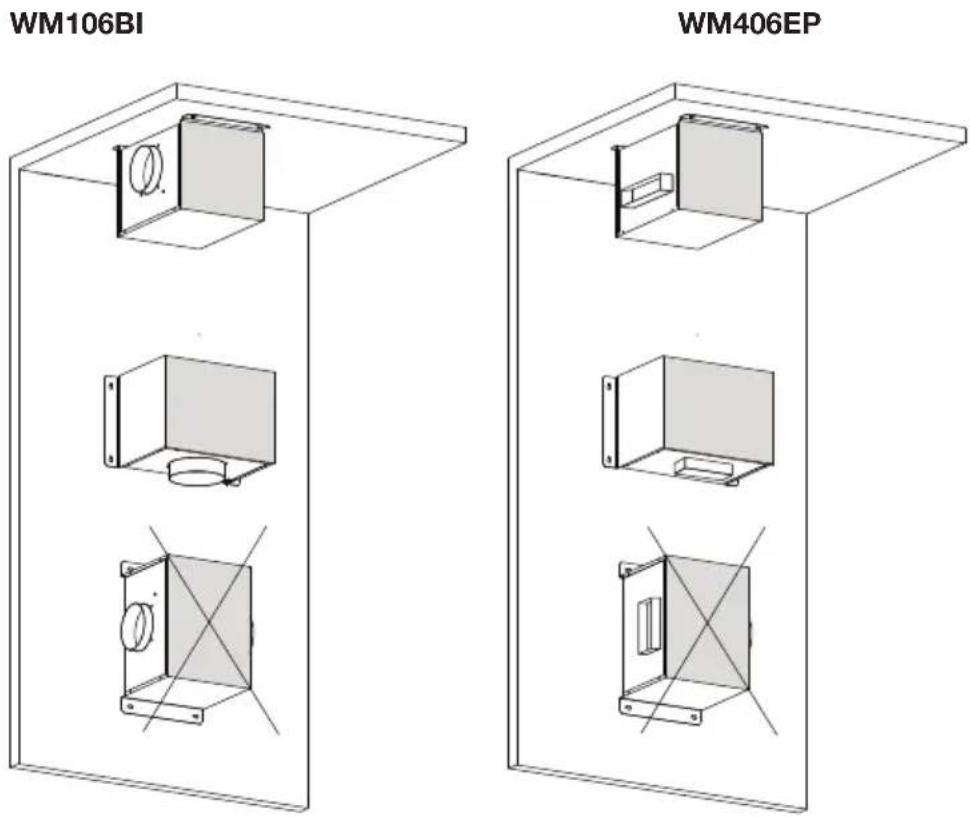
Installation instructions external motors
ATAG
WM406EP
WM106BI
WA511C
WD206BD
text_image
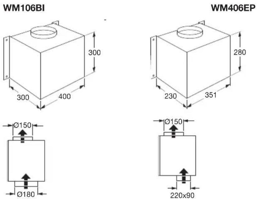
WM106BI WM406EPAfmetingen
text_image
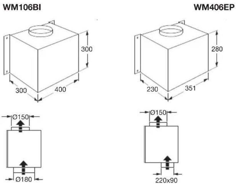
WM106BI 300 300 400 280 230 351 Ø150 Ø180 Ø150 220x90 WM406EPMontage
natural_image
3D rendering of a gray rectangular panel with a black mesh grille (no text or symbols)Afmetingen

text_image
400 452
natural_image
Front view of a computer monitor with multiple blank status indicators (no text or symbols visible)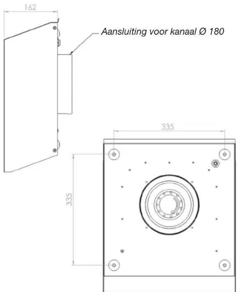
natural_image
Technical line drawing of a mechanical connector with multiple pins and a close-up inset showing a magnified detail (no text or symbols)
text_image
Technical diagram of an electrical connector with labeled pins and a close-up detail view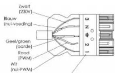
text_image
Zwart (230V) Blauw (nul-voeding) Geel/groen (aarde) Road (PWM) Wilt (nul-PWM)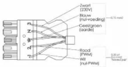
text_image
2wart [230V] Bkauw (nul-voeding) Ceev/groen (aarde) Road (PWM) Wit (nul-PWM) 0.75 mm² 0.25 ft 0.1 mm² Tested partnatural_image
Isometric line drawing of a mechanical component with layered structure (no text or symbols)Afmetingen
text_image
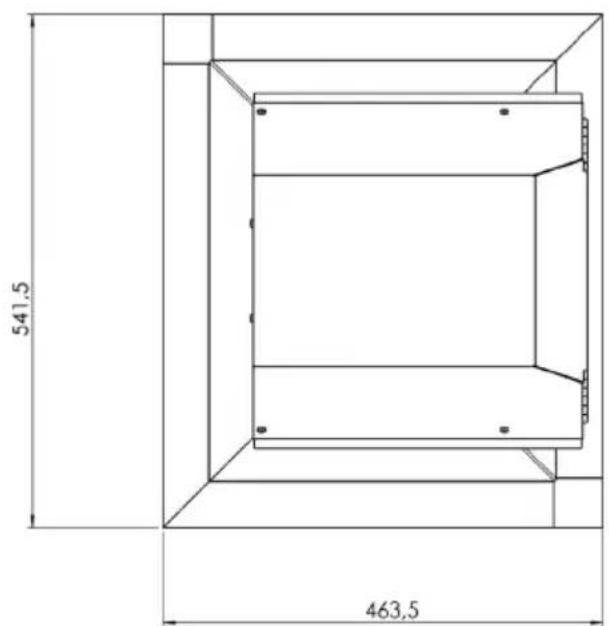
541,5 463,5
text_image
201,9 301 433 132,2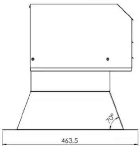
text_image
463,5 70°Montage

Aansluitschema
text_image
WM106BI WM406EPDimensions

text_image
WM106BI 300 400 300 280 351 230 Ø150 Ø180 Ø150 220x90 WM406EPInstallation
natural_image
3D rendering of a gray rectangular panel with a black mesh grille (no text or symbols)Dimensions

text_image
400 452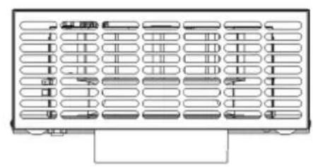
natural_image
Pure electrical circuit lines without any symbols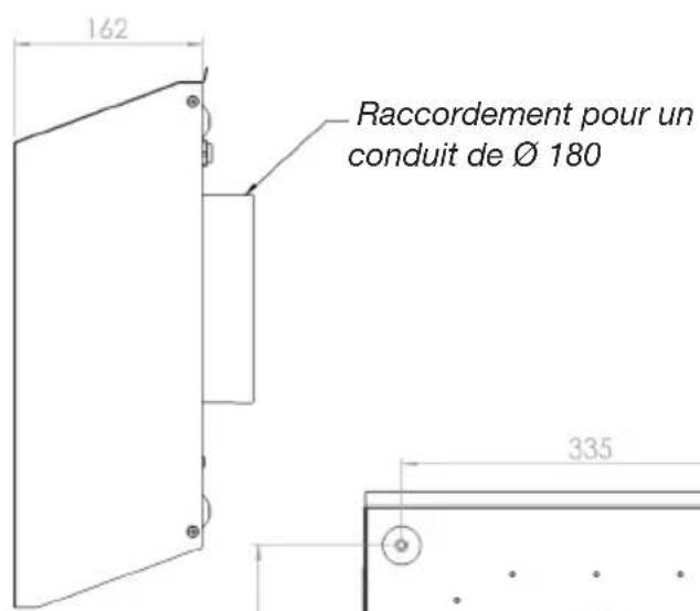
natural_image
Isometric line drawing of a mechanical component with layered structure (no text or symbols)Dimensions

text_image
541,5 463,5
text_image
201,9 301 433 132,2
text_image
463,5 70°Installation
text_image
WM106BI WM406EPAbmessungen

text_image
WM106BI 300 300 400 280 230 351 Ø150 Ø180 Ø150 220x90 WM406EPMontage
natural_image
3D rendering of a rectangular industrial component with internal grating (no text or symbols)Abmessungen
text_image
400 452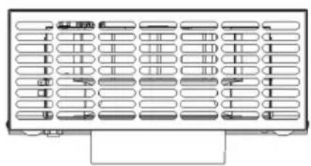
natural_image
Front view of a computer monitor with multiple blank status indicators (no text or symbols visible)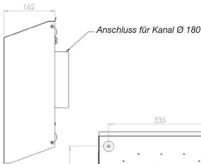
natural_image
Technical line drawing of a mechanical connector with multiple ports and a close-up inset showing a circular detail (no text or symbols)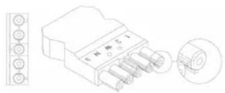
text_image
Technical diagram of an electrical connector with labeled pins and a magnified inset showing pin arrangement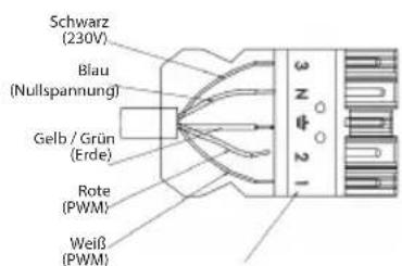
natural_image
Isometric line drawing of a mechanical component with layered structure (no text or symbols)Abmessungen
text_image
541,5 463,5
text_image
201,9 301 433 132,2
text_image
463,5 70°Montage

Connection diagram 5
Outdoor wall motor WA511C
Description 6
Dimensions 6
Assembly 7
Connection diagram 7
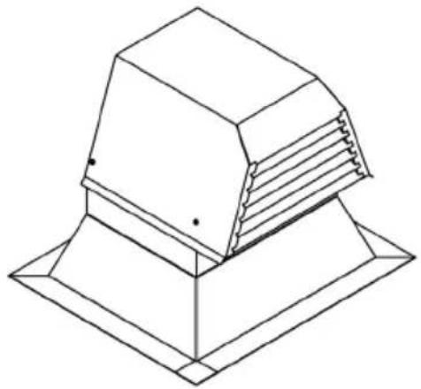
Flat roof motor WD206BD
Description 8
Dimensions 8
Assembly 9
Connection diagram 9
Description
Indoor motors can be mounted on walls, floors or ceilings. The principle is that the motor's axis must always lie horizontally. Indoor motors are not equipped with a non-return valve.
text_image
WM106BI WM406EPDimensions
text_image
WM106BI 300 400 300 280 351 230 Ø150 Ø180 Ø150 220x90 WM406EPAssembly
External motors are designed for installation indoors. When the external motor is included horizontally as part of the outlet piping it should be mounted on the floor. When the external motor is included vertically as part of the outlet piping it should be mounted on the wall.
- Determine the position of the external motor
- Secure the motor using the screws. Use the plugs when securing the motor to a stone wall or floor. Make sure that the outflow opening of the external motor is pointing in the right direction.
- Connect the external motor to the cooker hood in the kitchen.
- Connect the connection cable of the external motor to the connection cable of the cooker hood.
Please note: the motor's axis should always lie horizontally!
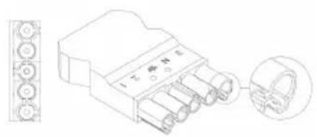
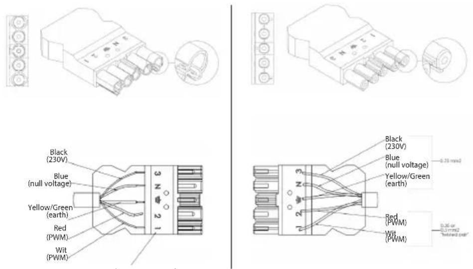
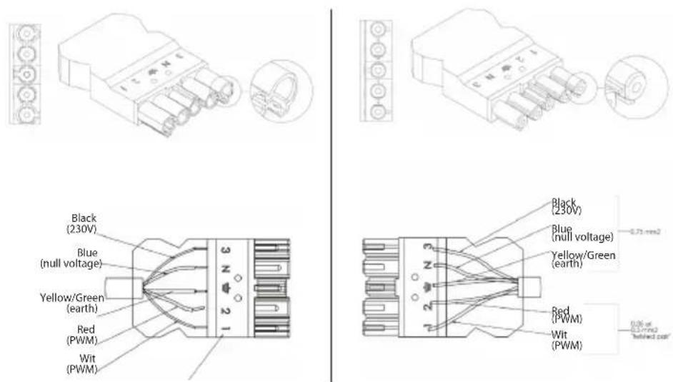
Connection diagram
Please note: NEVER switch the covers!!!
natural_image
Technical line drawing of a mechanical connector with inset view (no text or symbols)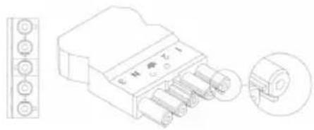
natural_image
Technical line drawing of a 4-pin electrical connector with pin labels and an inset view showing internal components (no text or symbols present)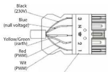
text_image
Black (230V) Blue (null voltage) Yellow/Green (earth) Red (PWM) Wit (PWM) 3 N 2 1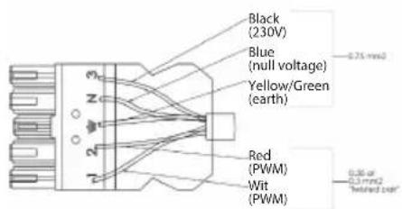
text_image
Black (230V) Blue (null voltage) Yellow/Green (earth) Red (PWM) Wit (PWM) 0.75 mm2 0.35 or 0.1 mm2 "elted part"Numbering of the 5-core cable
Description
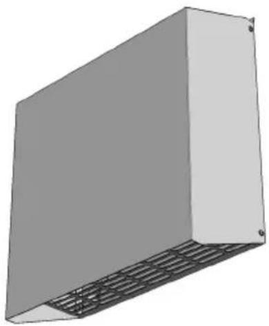
Outdoor wall motorWA511C
natural_image
3D rendering of a gray rectangular panel with a black mesh grille (no text or symbols)Dimensions

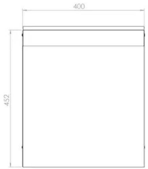
text_image
400 452
natural_image
Pure electrical circuit lines without any symbols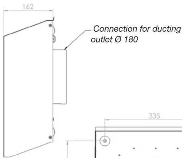
text_image
162 Connection for ducting outlet Ø 180 335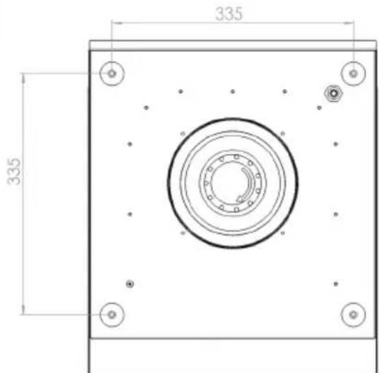
text_image
335 335Mounting holes
Assembly
- Determine positioning.
- Chip a hole of the desired diameter.
- Seal the motor housing by filling the gaps with foam from the inside.
- Connect cables and ducting.
- Any cracks that appear should be sealed with foam.
The outdoor wall motor is equipped with a non-return valve.
Connection diagram
Please note: NEVER switch the covers!!!
text_image
Black (230V) Blue (null voltage) Yellow/Green (earth) Red (PWM) Wit (PWM) Black (230V) Blue (null voltage) Yellow/Green (earth) Red (PWM) Wit (PWM) -0.75 mmol 0.36 or -0.5 mmol "eltired part"Numbering of the 5-core cable
Description
Flat roof motor WD206BD
natural_image
Isometric line drawing of a mechanical component with layered structure (no text or symbols)Dimensions
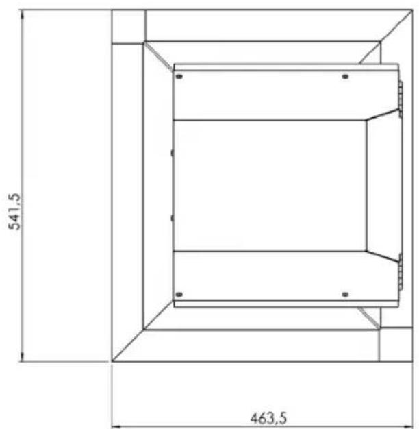
text_image
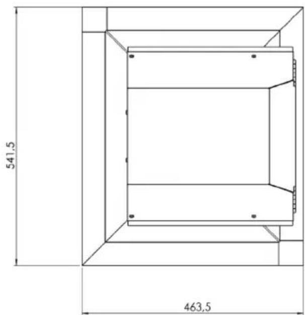
541,5 463,5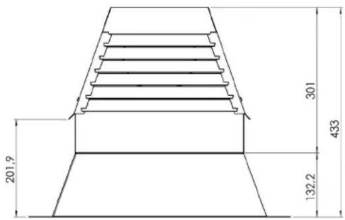
text_image
201,9 301 433 132,2
text_image
463,5 70°Assembly

- Determine positioning.
- Saw or drill hole of the desired diameter.
- Use supplied piping items to mount motor or culvert to existing bitumen (glue if necessary).
- Paste or melt new bitumen across the stainless steel plate, preferably a few centimetres up the edge (rising edge of 80mm).
- Connect cables and/or ducting.
- Any gaps that appear in the insulation should be sealed with foam.
Recommended: the arrow on the non-return value needs to point in the waste air direction.
Connection diagram

Please note: NEVER switch the covers!!!
text_image
Black (230V) Blue (null voltage) Yellow/Green (earth) Red (PWM) Wit (PWM) 3 4 2 1 2 3 N N N N Black (230V) Blue (null voltage) Yellow/Green (earth) Red (PWM) Wit (PWM) -0.75 mm² 0.06 of 0.3 mm² "whipped cell"Numbering of the 5-core cable
text_image
Warning symbol with exclamation mark inside a triangleThe appliance rating label is located on the inside of the appliance.
When contacting the service department, have the complete type number to hand.
Addresses, phone number of the service organisation and the warranty
conditions can be found at www.atag.nl or www.atag.be