
WV6092A - Basket Atag - Free user manual and instructions
Find the device manual for free WV6092A Atag in PDF.

User questions about WV6092A Atag
0 question about this device. Answer the ones you know or ask your own.
Ask a new question about this device
Download the instructions for your Basket in PDF format for free! Find your manual WV6092A - Atag and take your electronic device back in hand. On this page are published all the documents necessary for the use of your device. WV6092A by Atag.
USER MANUAL WV6092A Atag
Instructions for use
Cooker hood
ATAG
WV6092 ---
natural_image
Warning symbol with light bulb and exclamation mark (no text or numbers)natural_image
Hand holding a directional arrow icon on a circular surface, pointing at a small rectangular object (no text or symbols present)natural_image
Illustration of a hand holding a tool with a circular object, no text or symbols present
natural_image
Line drawing of a hand holding a small object, possibly a knob or dial (no text or symbols)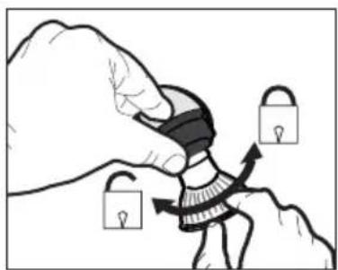
natural_image
Illustration of a hand holding padlocks with arrows indicating movement (no text or symbols)text_image
DC (V) OUTtext_image
Technical diagram showing a 3D mechanical housing with internal components and a schematic of a DC power supply connected to a box.
text_image
Diagram illustrating a mechanical or optical setup with labeled components and directional arrows, likely from an engineering or physics context.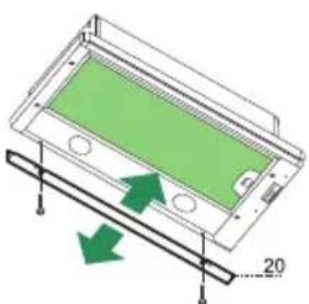
natural_image
Diagram of a device with green screen and directional arrows indicating movement or force (no text or symbols)Sluitprofiel
natural_image
Two symbolic icons: a light bulb above a triangular warning sign with an exclamation mark below (no text or labels)natural_image
Hand pointing at a circular diagram with an arrow and a small circle, no text or symbols present.natural_image
Illustration of a hand holding a tool with a circular object, no text or symbols present
natural_image
Line drawing of a hand holding a small mechanical component (no text or symbols)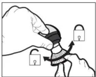
natural_image
Illustration of a hand holding a padlock over a stylized figure, with arrows indicating movement or process (no text or symbols)$$ \text { MARRON } = \text { Phase (L) } $$
$$ \mathrm{BLEU} = \text { N e u t r e } (\mathrm{N}) $$
text_image
DC (V) OUTtext_image
Technical diagram showing a 3D mechanical housing with labeled components and an electrical circuit diagram with DC voltage inputs.
text_image
Diagram illustrating a mechanical or optical setup with labeled components and directional arrows, likely from an engineering or physics context.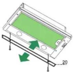
natural_image
Diagram of a green panel inside a transparent housing with arrows indicating direction, no text or symbols presentProfil de fermeture
text_image
Prohibition sign with crossed-out trash bin and no text or symbolsnatural_image
Hand pointing at a circular diagram with an arrow and a small circle, no text or symbols present.natural_image
Illustration of a hand holding a tool with a circular object and arrow indicating rotation (no text or symbols)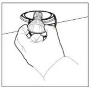
natural_image
Line drawing of a hand holding a small object, possibly a knob or knob (no text or symbols present)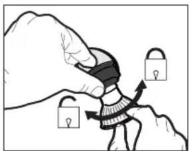
natural_image
Illustration of a hand holding a padlock over a stylized figure, with arrows indicating movement or change (no text or symbols)text_image
DC (V) OUTtext_image
Technical diagram showing a mechanical housing with labeled components and a schematic of a DC power connection panel.
text_image
Diagram illustrating a physical setup with labeled components and directional arrows, likely from an optics or engineering context.
natural_image
3D diagram of a device with green screen and arrows indicating motion or force, no text or symbols presentAbschlussprofil
text_image
Prohibition sign with crossed-out trash bin and no text or symbolsReplacing the LED lighting 7
Installation
General 8
Electrical connection 9
Assembly 10
Annex
Disposal 12
Introduction

natural_image
Warning symbol with light bulb and exclamation mark (no text or numbers)Reading through these instructions for use will help you quickly find information about all the options you are offered by this appliance. It contains information for your safety and about the maintenance of the appliance.
Keep the instructions for use and the installation instructions. They will be of value to any later user of this appliance.
Read the separate safety instructions before using the appliance.
Description
text_image
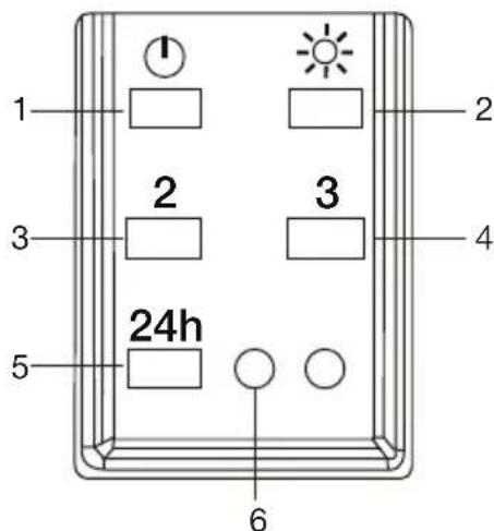
1 2 3 4 5 24h 6- Switch on/off + fan speed 1
- Switch lighting on/off
- Fan speed 2
- Fan speed 3
- Switch 24-hour ventilation mode on/off
- Indication of extraction on/off
Operation
Switching the fan on and off
- Switch the fan on with the on/off key (1)
- Select the required extraction speed by pressing '3' or '4'.
- Press key 5 to switch on 24-hour ventilation mode. Every hour the cooker hood will operate at setting 2 for 10 minutes.
Switching the lighting on and off
- Switch the lighting on and off with the '2' key.
Cleaning

Attention! Before carrying out maintenance work, always disconnect the cooker hood from the power supply by pulling the plug out of the socket or by switching off the power at the fuse box. The hood must be cleaned regularly, both inside as well as outside (with at least the same regularity as used for cleaning the grease filters). Do not use any products that contain abrasive materials.
Do not clean with alcohol!
Attention! If you do not follow these instructions with regards to the cleaning of the appliance and the cleaning or replacement of the filters, this can lead to fire. It is essential to follow these instructions!
The manufacturer is not liable for damage to the motor or damage as a result of fire that is due to improper servicing or not following the above safety requirements.
Cooker hood
Clean the cooker hood with a soft cloth with water and a little detergent. Then wipe with clean water. Do not use aggressive cleaning agents such as soda. The cooker hood's coating will remain in good condition when you occasionally wax the coating.

Stainless steel hoods
Do not use scouring sponges or other abrasives on stainless steel hoods. Give a finishing clean with a non-abrasive, non-polishing agent and rub in the direction of the surface finish of the stainless steel.
Metal grease filters
Metal filters must be cleaned once a month (or when indicated by the filter cleaning indicator, if fitted to the model) with neutral cleaning agents, by hand or in the dishwasher at low temperatures using a short programme. Put the grease filters in the dishwasher with the openings facing down so that the water can drain. Aluminium grease filters will become dull from the cleaning agents in the dishwasher. This is normal, and does not affect the performance.
Grease filters
natural_image
Hand holding a tool interacting with a circular diagram showing a curved arrow (no text or symbols)Removing the grease filters
Switch the power supply off! Remove the plug from the socket or turn the switch in the meter cupboard to '0'. Remove the filters one by one by pulling on their release handles.
Replacing the LED lighting

The lamp in this household appliance is only suitable for illumination of this appliance. The lamp is not suitable for household room illumination.
Attention!
Disconnect the cooker hood from the power supply by pulling the plug out of the socket or by switching off the power at the fuse box.
natural_image
Illustration of a hand holding a tool with a circular object and arrow indicating rotation (no text or symbols)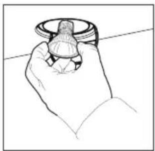
natural_image
Line drawing of a hand holding a knob or dial (no text or symbols)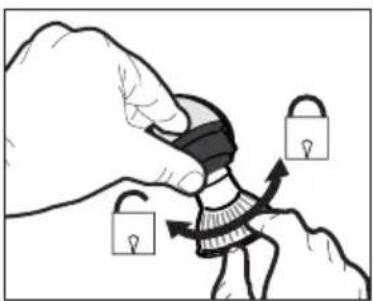
natural_image
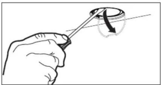
Illustration of a hand holding a padlock and securing a person's seat, with no text or symbols present.- Carefully open the clip for the bulb with a screwdriver.
- Carefully remove the lamp from the hood.
- Turn the bulb a quarter of a turn clockwise and remove it from the socket.
- Place the new lamp in the reverse order of the described steps.
- Put the power cord back in the socket and check for correct operation.
| Lamp | Power (W) | Socket | Voltage (V) | Dimensions (mm) | ILCOS Code |
| 5 GU10 230 | 52 x 50 DR | PAR-5/840- | 220/240- | GU10-35/36DRPAR-5/830-220/240-GU10-35/36 |
General
This appliance must be connected to the power supply by a recognised installer who is familiar with and works in accordance with the applicable safety regulations. This appliance conforms to the European directives.
Important information:
- The lowest part of the cooker hood must be at least 65 cm above a gas hob. The lowest part of the cooker hood must be at least 50 cm above an electric, ceramic or induction hob.
- The cooker hood may only be connected to an existing exhaust duct to which no other appliances are connected (such as a geyser or heater).
- Gas appliances must be vented in accordance with the local regulations.
- The cooker hood works best when connected to an exhaust duct that is as short and as straight as possible.
- Before drilling any holes, always check to make sure that there are no wires in the area.
- The hood's connection pipe has a diameter of 150 mm. The exhaust duct should preferably be of the same diameter.
- The installation materials supplied with this cooker hood are suitable for reinforced concrete and masonry walls. You will need special plugs and screws to fasten the appliance to some other types of wall.
Electrical connection
This is an (insulation) class II (double insulated) appliance. The cable does not therefore need to be connected to an earthed socket.
Check to make sure that the voltage specified on the type plate matches the mains voltage.
The appliance must be connected to the mains as follows:
$$ B R O W N = L (\text { live }) $$
$$ \text { BLUE } = \text { N (neutral) } $$
This cooker hood is fitted with a plug. Install the cooker hood so that the plug is accessible.
text_image
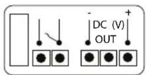
DC (V) OUTConnection to a HRU or CMV unit
Check which connection best suits your ventilation situation. Choose from the options below of potential free contact or voltage control.
- Use the potential-free connection on the connector block. This switches your ventilation system to the maximum setting.
- Use the Voltage control signal DC (V). This switches your ventilation system via the settings on the cooker hood.
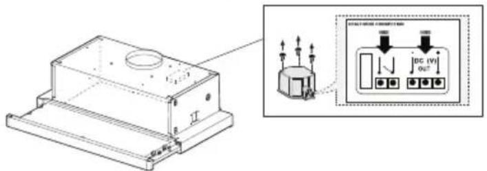
text_image
Technical diagram showing a mechanical housing with labeled components and an electrical panel connection diagram.
Note: When you make a fixed connection to the mains you must make sure that the live wire is connected to an omnipolar switch with a break contact distance of at least 3 mm.
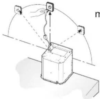
text_image
Diagram illustrating a robotic arm interacting with a device, showing input/output signals and control points.max. 100 cm
Assembly
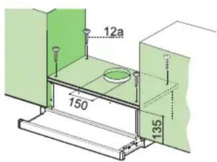
Drilling holes in the supporting surface and mounting the hood
- The supporting surface for the hood must be 135 mm higher than the lower edge of the suspended cabinets.
- Drill a 4.5 mm diam. hole in the support using the supplied drilling template.
- Drill a 150 mm diam. hole in the supporting surface using the supplied drilling template.
- Secure with the 4 supplied screws '12a' (4.2 x 44.4).
text_image
12a 150 135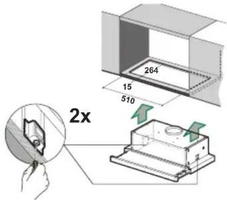
text_image
264 15 510 2xMounting the cooker hood in a cabinet without a shelf
- Saw an opening of 510 × 265 ~cm in the bottom of the cabinet.
- Mount the cooker hood in the cabinet opening using the two quick-release clamps.
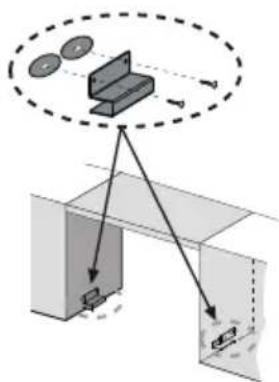
- Mount the cooker hood using the supplied cabinet brackets and quick-release clamps if the bottom panel of the cabinet is missing.
text_image
Diagram illustrating a mechanical or optical setup with labeled components and directional arrows, likely from an engineering or physics context.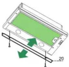
natural_image
Diagram of a green panel mounted on a wooden base with arrows indicating direction (no text or symbols)Closing profile
- The space between the edge of the hood and the rear wall can be closed with the supplied profile '20' using the screws that are already available for this purpose.
text_image
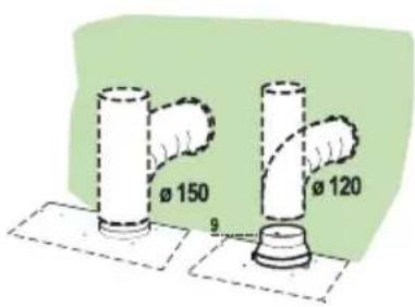
Ø 150 Ø 120 9Connections
Connect the cooker hood to a rigid or flexible hose of diameter 150 or 120 mm.
- For connection to a 120 mm diam. hose, the reduction flange '9' must be attached to the cooker hood outlet.
- Secure the hose with suitable hose clamps. The required materials are not supplied with the cooker hood.
Disposal
Disposal of packaging and appliance
Sustainable materials were used in the manufacture of this appliance. At the end of its life cycle, this appliance must be disposed of in a responsible manner. You can obtain more information from the authorities.
The packaging of the appliance is recyclable. The following materials may have been used:
- cardboard;
• polyethylene foil (PE);
• CFC-free polystyrene (PS hard foam).
These materials must be disposed of in a responsible manner and in accordance with government regulations.
text_image
Prohibition sign with crossed-out trash bin and no text or symbolsThe appliance is marked with a crossed out wheeled bin symbol to draw your attention to the requirement for the separate disposal of domestic electrical appliances. This means that the appliance may not be disposed of in unsorted household waste at the end of its service life. The appliance must be taken to a special municipal waste processing location for separated waste or to a dealer who provides this service.
Collecting and disposing of domestic appliances separately avoids the potential detrimental consequences for the environment and health that can result from unsuitable processing. This ensures that the materials used to make the appliance can be recovered and that substantial savings in the use of energy and raw materials can be achieved.

Declaration of conformity
We hereby declare that our products conform to the applicable European Directives, Regulations and requirements, as well as all requirements in the standards to which reference is made.
ATAG

text_image
Barcode image containing machine-readable data, with vertical black and white lines representing the number 10844196