
WS9011DL - Basket Atag - Free user manual and instructions
Find the device manual for free WS9011DL Atag in PDF.

User questions about WS9011DL Atag
0 question about this device. Answer the ones you know or ask your own.
Ask a new question about this device
Download the instructions for your Basket in PDF format for free! Find your manual WS9011DL - Atag and take your electronic device back in hand. On this page are published all the documents necessary for the use of your device. WS9011DL by Atag.
USER MANUAL WS9011DL Atag
Instructions for use
Cooker hood
ATAG
WS70__DL
WS90__DL
natural_image
Warning symbol with light bulb and triangular warning triangle (no text or numbers)natural_image
Diagram of a staircase with brick walls and a cabinet, showing airflow direction (no text or symbols)natural_image
Diagram of a vertical structure with brick wall and hanging panel, showing airflow direction (no text or symbols)Bediening
▶De afzuiging stopt.
text_image
Diagram illustrating hand positioning and movement of a tool, with numbered annotations indicating steps 1 and 2.text_image
Diagram illustrating a process with warning symbol and magnified detail, showing steps of installation or inspection.
text_image
Diagram showing a device with labeled components and signal paths, including a sensor or indicator on the screen.text_image
Prohibition sign with crossed-out trash bin and no text or symbolsnatural_image
Diagram of a staircase with brick walls and a cabinet, showing airflow direction (no text or symbols)natural_image
Diagram of a vertical structure with brick wall and adjacent panel, showing airflow or movement arrows (no text or symbols)Commandes
flowchart
graph TD
    A["Warning Sign"] --> B["Initial State"]
    B --> C["Magnified Detail"]
    C --> D["Final Output"]
natural_image
Diagram of a device with a hand interacting with a sensor or sensor, connected to a box and two sensors (no text or symbols present)text_image
Prohibition sign with crossed-out trash bin and no text or symbolsnatural_image
Warning symbol with light bulb, exclamation mark, and triangular warning triangle (no text)natural_image
Diagram of a building interior with brick walls, stairs, and ventilation system (no text or labels)natural_image
Diagram of a vertical structure with brick walls and a cabinet, showing airflow direction (no text or symbols)Bedienung
text_image
Diagram illustrating hand positioning and movement of a device with labeled parts and directional arrows
natural_image
Diagram of a mechanical or electrical setup with a box, wires, and three labeled components (no text or symbols present)text_image
Prohibition sign with crossed-out trash bin and no text or symbols| Introduction Description | 4 | |||
| Safety | ||||
| Exhaust | systems | |||
| Use | ||||
| Controls | 6 | |||
| Maintenance | ||||
| Cleaning | 7 | |||
| Grease | filters | |||
| Odour/fine | particle | filter | ||
| Lighting | 9 | |||
| Installation | ||||
| General | 10 | |||
| Electric | connection | 11 | ||
Environmental aspects
| Disposal of packaging and appliance | 12 |
Introduction
natural_image
Warning symbol with light bulb and triangular warning triangle (no text or numbers)This user manual gives you a quick overview of all the possibilities offered by the appliance. You will find information on safety measures and maintaining the appliance.
Please retain this user manual and the installation guide.
They may be of use to future users of the appliance.
Please read the separate safety instructions carefully before using the appliance!
You can find the most recent version of the instructions for use on our website.
Description
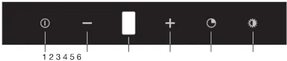
text_image
1 2 3 4 5 6- On/Off key
- Minus (-) key
▶Reduce the extractor capacity - Display
▶Shows the extractor settings
▶Shows an active timer
▶Shows the intensive setting
▶ Shows the saturation of the grease filters and the odour filters - Plus (+) key
▶Increase the extractor capacity - Timer key
- Lighting key
Read the separate safety instructions before using the appliance.
Exhaust systems
natural_image
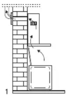
Diagram of a staircase with brick walls and a cabinet, showing airflow direction (no text or symbols)This cooker hood has two exhaust systems which work in parallel:
- As a cooker hood connected to a central extraction system:
The cooking fumes are drawn into the cooking hood, filtered, and exhausted outdoors via the central extraction system.
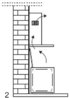
- As a recirculation cooker hood:
The cooking fumes are drawn into the cooking hood, and the grease droplets, odours and fine particles are filtered out. The clean air is then returned to the kitchen.
natural_image
Diagram of a vertical structure with brick wall and support frame, showing directional arrows indicating movement or force (no text or symbols)Controls
Starting the exhaust system
- Touch the on/off key.
The exhaust system starts at setting 1.
The display shows the exhaust setting.
- Change the exhaust setting with the plus (+) key or minus (-) key.
▶You can choose setting 1, 2, 3, 4 or an intensive setting.
The intensive setting
You can temporarily switch the extractor hood to the intensive setting, for example, to remove the odour quickly if something has burned.
- In setting 4, touch the plus (+) key again.
Setting 5 flashes on the display. The extractor hood switches to its highest setting for 6 minutes, and then switches back to the original setting.
▶ Touch the minus (-) key to switch off the intensive setting before the 6 minutes have elapsed.
Stop the exhaust system
- Touch the on/off key.
The exhaust system stops.
Switching on the timer
- Start the exhaust system and choose setting 1, 2, 3 or 4.
- Touch the timer key.
The exhaust setting flashes on the display. The hood switches off automatically after 15 minutes.
▶ Touch the timer key again to switch off the timer before the 15 minutes have elapsed.
▶You cannot use the timer with the intensive setting.
Switching the lighting on and off
- Touch the lighting key.
The lighting comes on.
- Press the lighting key again.
The lighting goes off.
Cleaning
Attention!
- Before performing any maintenance operation, isolate the hood from the electrical supply by unplugging the appliance or switching off your household's master switch.
- The cooker hood should be cleaned regularly (at least as frequently as the grease filters are cleaned) both internally and externally. Do not use abrasive products. Do not use alcohol!
- Failure to comply with the basic recommendations for cleaning the cooker hood and cleaning/replacing the filters may lead to a fire. Therefore, we recommend that you observe these instructions.
- The manufacturer declines all responsibility for any damage to the motor or any fire damage linked to inappropriate maintenance or failure to observe the above safety recommendations.
Cooker hood
- Clean the cooker hood with soapy water and a soft cloth. Then wipe with clean water to rinse.
- Do not apply aggressive cleaning agents such as caustic soda.
- The paintwork on the cooker hood will remain shiny if it is periodically rubbed with wax.
Stainless steel canopy hoods
- Do not use any sort of scourer.
- Treat with a stainless steel care product and polish with the structure of the stainless steel.
Grease filters
Saturation of the grease filters
After 30 operating hours, the exhaust setting and 'F' flash alternately on the display. The grease filters must be cleaned.
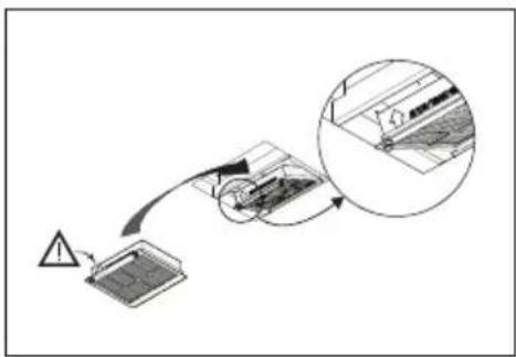
text_image
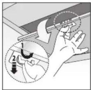
Diagram illustrating hand positioning and movement of a device with labeled parts and directional arrowsRemoving the grease filters
Pull the lever down and tilt the grease filter down.
Cleaning the grease filters
- Clean metal grease filters every 2 months or when the display indicates this.
- Clean either by hand or in the dishwasher, which must be set to a low temperature and a short cycle.
- The openings must be placed downwards to let the water run out of the filters.
It is important that the grease filters are properly dried before replacing them.
Reset the memory after replacing the grease filters. Switch on the extractor hood and touch and hold the On/Off key for 3 seconds; 'F' will stop blinking.
Odour/fine particle filter
General:
- More noise is produced when odour filters are used than when the cooker hood is used with an exhaust vent.
- Odour filters function optimally at a lower motor speed.
Consequently, you should avoid the intensive setting as much as possible.
Saturation of the odour/fine particle filter
After 300 operating hours, the exhaust setting and 'C/F' flash alternately on the display. The odour filters must be cleaned.
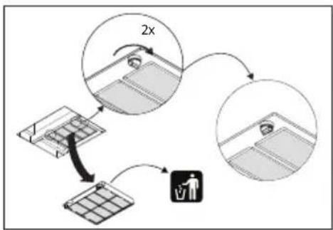
Replacing the odour/fine particle filter
The odour/fine particle filter must be replaced annually (or when indicated by the filter cleaning indicator). To replace the filter, follow the instructions supplied with the new filter.
Important:
- The saturation of the filter depends on the intensity of use, the manner of cooking and the regularity with which the grease filters are cleaned.
flowchart
graph TD
    A["Solar Panel"] -->|2x| B["Person using Device"]
    B --> C["Device"]
flowchart
graph TD
    A["Warning Triangle"] --> B["Device with Contour"]
    B --> C["Arrow pointing to the component"]
    C --> D["Crossing Diagram"]
    D --> E["Internal Structure"]
    E --> F["Arrow pointing to the component"]
    F --> G["Final Panel"]

Reset the memory after replacing the odour filter. Switch on the extractor hood and touch and hold the On/Off key for 3 seconds; 'C/F' will stop blinking.
Lighting
This hood is fitted with a light system. This light system has to be replaced by an authorized technician. Do not attempt to replace it by yourself.
The lamp in this household appliance is only suitable for illumination of this appliance. The lamp is not suitable for household room illumination.
General
This appliance must be connected to the electric mains and the central extraction system by an authorised installer who is familiar with the safety precautions and will carry them out. The appliance is in compliance with European guidelines.
Important information:
- The distance between the lowest point of the cooker hood and a gas hob must be at least 65 cm. If using an electric, ceramic or induction hob, this distance must be at least 55 cm.
- If the cooker hood is connected to an existing exhaust duct, no other appliance must be connected to the duct (such as a hot water heater or a stove).
- Consider local regulations with respect to the ventilation of gas appliances.
- The shorter the duct, and the fewer bends in it, the better the cooker hood will work.
- Check before you start drilling that no installation pipe(s) is/are present.
- The connection pipe to the cooker hood has a diameter of 150 mm. We recommend that the exhaust pipe has as large a diameter as possible.
- The enclosed installation materials are suitable for reinforced concrete and brick walls. For some types of wall you may need special plugs and screws.
Electric connection
The appliance has been manufactured as a class II, therefore no earth cable is necessary.
Make sure the supply voltage ratings correspond with those stated on the appliance data plate. The connection to the mains is carried out as follows:
BROWN = phase L
BLUE = phase N
This canopy hood has been provided with a power plug.
When installing the hood, make sure that this plug remains accessible.
We recommend installing the wall socket out of view, behind the chimney cover.
Attention:
If you want to make a fixed connection, ensure that a multi-pole switch with a distance between contacts of 3 mm is installed in the supply cable.
max 100 cm
text_image
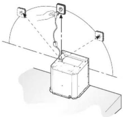
Diagram showing a hand holding a device with an attached sensor, connected to a box and three labeled sensors at the top.Disposal of packaging and appliance
Sustainable materials have been used during manufacture of this appliance. This appliance must be disposed of responsibly at the end of its service life. Ask your local authorities for more information about how to do this.
The appliance packaging is recyclable. The following materials may have been used:
- cardboard;
• polyethylene film (PE);
• CFC-free polystyrene (PS rigid foam).
Dispose of these materials in a responsible manner and in accordance with government regulations.
text_image
Prohibition sign with crossed-out trash bin and no text or symbolsThe product has been marked with a crossed-out dustbin symbol to remind you of the obligation to dispose of electrical household appliances separately. This means that the appliance may not be included with normal domestic refuse at the end of its service life. The appliance must be taken to a special municipal centre for separated waste collection or to a dealer providing this service.
Separate collection of household appliances helps to prevent any potential negative impact on the environment and on human health caused by improper disposal. It ensures that the materials of which the appliance is composed can be recovered to obtain significant savings in energy and raw materials.
CE
Declaration of Conformity
We hereby declare that our products satisfy the applicable European Directives, Orders and Regulations, as well as the requirements stated in the referenced standards.
The instructions for use can also be found on our website:
www.atag.nl
www.atag.be