BIO120TR - Mechanical chipper Anova - Free user manual and instructions
Find the device manual for free BIO120TR Anova in PDF.

User questions about BIO120TR Anova
0 question about this device. Answer the ones you know or ask your own.
Ask a new question about this device
Download the instructions for your Mechanical chipper in PDF format for free! Find your manual BIO120TR - Anova and take your electronic device back in hand. On this page are published all the documents necessary for the use of your device. BIO120TR by Anova.
USER MANUAL BIO120TR Anova
natural_image
Exterior view of a modern agricultural machine with visible tracks and control panels (no text or symbols)ES
ANOVA®
natural_image
Line drawing of a tracked robotic vehicle on a platform (no text or symbols)A. Pasador de bisagra
(1A). Perilla
(2A). Pasador de bisagra
4.1.4. Deflector
natural_image
Diagram of a mechanical assembly with rotating blades and connecting rods (no text or symbols)
A. Manija de parada de emergencia
4.3.4. Ralentí
natural_image
Technical illustration of a tracked robotic vehicle with mechanical components and bolts (no text or symbols)natural_image
Technical diagram of a robotic vehicle showing track and chassis components with no visible text or symbolsA. Cojinete interior

natural_image
Technical line drawing of a mechanical device with gears and components (no text or symbols)
natural_image
Technical line drawing of a mechanical assembly with no visible text or symbolsAdvertencia
natural_image
Technical line drawing of a mechanical device with a central circular component and surrounding components (no text or symbols)
A. Placa de desgaste
natural_image
Technical line drawing of a mechanical device with two circular insets highlighting features (no text or symbols)natural_image
Mechanical assembly diagram showing a motor with pulleys and a magnified inset of a belt drive mechanism (no text or symbols)natural_image
Mechanical assembly diagram showing a belt drive mechanism with pulleys and gears (no text or labels)ES
10. CERTIFICADO CE
natural_image
Exterior view of a modern agricultural machine with visible branding and control panel (no text-heavy elements)PT
ANOVA®
natural_image
Line drawing of a tracked robotic vehicle on a platform, no text or symbols presentC. Alavanca de paragem de
natural_image
Diagram of a mechanical device with multiple blades and a central handle, showing rotational motion arrows (no text or symbols)
A. Porca de ajuste
natural_image
Technical illustration of a tracked vehicle with mechanical components and bolts, no visible text or symbolsnatural_image
Technical diagram of a robotic vehicle showing track and chassis components with directional arrows indicating motion (no text or labels)PARA.Rolamento interno
natural_image
Technical line drawing of a mechanical device with no visible text or symbols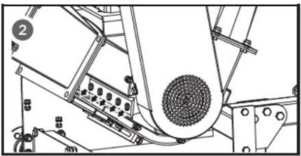
natural_image
Technical line drawing of a mechanical device with rollers and components (no visible text or symbols)Aviso
A. Placa de desgaste
natural_image
Technical line drawing of a mechanical device with a magnified inset showing a bolt and nut (no text or symbols)natural_image
Technical illustration of a mechanical assembly with a magnified inset showing a hand pulling a belt drive system (no text or symbols present)natural_image
Mechanical assembly diagram showing a motor with rotating components and directional arrows (no text or labels)
10. CERTIFICADO CE
natural_image
Exterior view of a modern agricultural machine with visible engine and tracked wheels (no text or symbols)FR
ANOVA®
NE PAS PLACER LES MAINS SOUS CETTE LIGNE
natural_image
Line drawing of a tracked robotic vehicle on a platform (no text or symbols)FR
A. Axe de charnière
(1A). Bouton
(2A). Axe de charnière
4.1.4. Déflecteur
natural_image
Diagram of a mechanical assembly with intersecting rods and a central rotating rod (no text or symbols)
INTERDICTION DE PASSER LES MAINS EN DESSOUS DE CETTE LIGNE
natural_image
Technical illustration of a tracked robotic vehicle with mechanical components and bolts (no text or symbols)FR
natural_image
Technical diagram of a robotic vehicle showing track and chassis components with directional arrows indicating movement (no text or labels)À.palier intérieur
FR
natural_image
Technical line drawing of a mechanical device with gears and components (no text or symbols)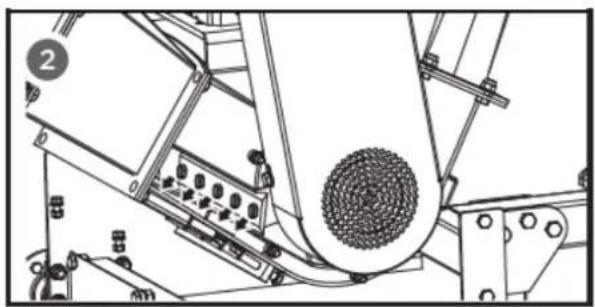
natural_image
Technical line drawing of a mechanical assembly with no visible text or symbolsAvertissement
natural_image
Technical line drawing of a mechanical assembly with no visible text or symbols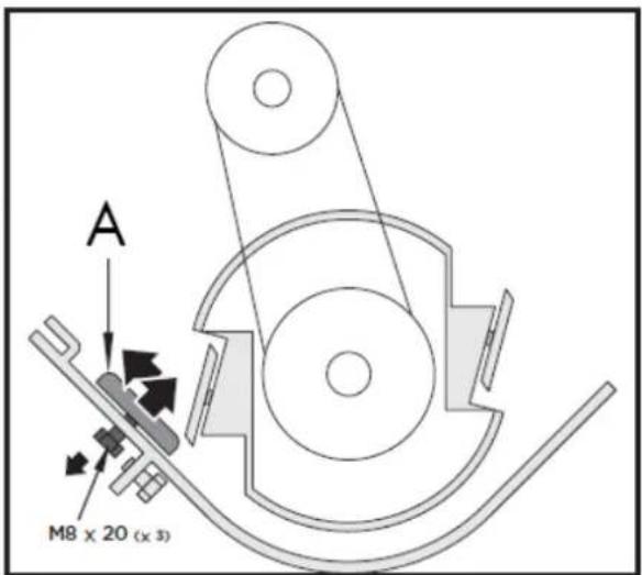
A. Plaque d'usure
natural_image
Technical line drawing of a mechanical device with a magnified inset showing a bolt and nut (no text or symbols)natural_image
Mechanical assembly diagram showing a motor with pulleys and a magnified inset of a belt drive mechanism (no text or symbols)natural_image
Mechanical assembly diagram showing a linkage mechanism with no visible text or symbolsFR
FR

SOCIÉTÉ DE DISTRIBUTION
MILLASUR, SLU
DÉCLARATION DE CONFORMITÉ CE
Directive 2006/42/CE
2000/14/CE
2005/88/CE
natural_image
Exterior view of a large industrial snowfaller with visible engine and tracks (no text or symbols)IT
ANOVA®
natural_image
Technical line drawing of a tracked robotic vehicle on a platform (no text or symbols)natural_image
Diagram of a mechanical device with multiple blades and a central handle, showing rotational motion arrows (no text or symbols)
C. Controdado.
natural_image
Technical illustration of a tracked robotic vehicle with mechanical components and bolts (no text or symbols)IT
natural_image
Technical diagram of a robotic vehicle showing track and chassis components with no visible text or symbols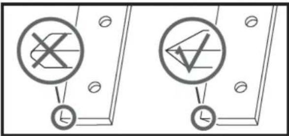
natural_image
Technical line drawing of a mechanical device with gears and components (no text or symbols)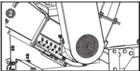
natural_image
Technical line drawing of a mechanical assembly with no visible text or symbolsAvvertimento
natural_image
Technical line drawing of a mechanical device with a central circular component and surrounding components (no text or symbols)
A. Piastra antiusura
natural_image
Technical line drawing of a mechanical device with a magnified inset showing a bolt and nut (no text or symbols)natural_image
Technical illustration of a mechanical assembly with a magnified inset showing a hand pulling a belt drive (no text or symbols present)natural_image
Mechanical assembly diagram showing a belt drive mechanism with pulleys and gears (no text or labels)IT

Instructions and user manual
natural_image
Exterior view of a modern agricultural machine with visible engine and tracked wheels (no text or symbols)EN
ANOVA®
Anova We would like to congratulate you on choosing one of our products and guarantee the assistance and cooperation that has always distinguished our brand over time.
This machine is designed to last for many years and to be of great use if used according to the instructions in the user manual. We therefore recommend that you carefully read this instruction manual and follow all our recommendations.
For more information or questions, you can contact us through our web support at www.anova.es.
INFORMATION ABOUT THIS MANUAL
Pay attention to the information provided in this manual and on the appliance for your safety and the safety of others.
- This manual contains instructions for use and maintenance.
- Take this manual with you when you go to work with the machine.
- The content is correct at the time of printing.
- We reserve the right to make changes at any time without affecting our legal responsibilities.
- This manual is considered an integral part of the product and must remain with it in case of loan or resale.
- Request a new manual from your distributor if it is lost or damaged.
READ THIS MANUAL CAREFULLY BEFORE USING THE MACHINE

To ensure your machine delivers the best results, carefully read the usage and safety guidelines before using it.
OTHER WARNINGS:
Improper use could cause damage to the machine or other objects.
Adapting the machine to new technical requirements could cause differences between the content of this manual and the product purchased.
Read and follow all instructions in this manual. Failure to follow these instructions could result in serious personal injury.
INDEX
- SAFETY INSTRUCTIONS
- PRODUCT DESCRIPTION
- TECHNICAL SPECIFICATIONS
- ASSEMBLY AND INSTRUCTIONS FOR USE
- MAINTENANCE AND STORAGE
- TROUBLESHOOTING
- WARRANTY
- ENVIRONMENT
- EXPLODED VIEW
10.CE CERTIFICATE
1. SAFETY INSTRUCTIONS
1.1. Safety instructions
▲ Important
Before operating this product, please read and follow the instructions below. To prevent injury to yourself and others, you should also follow local safety regulations.
Keep these instructions for future reference. This manual contains safety information to inform you about the hazards and risks associated with the product and how to prevent them. It also contains important instructions that must be followed during product setup, operation, and maintenance.
It is important that you read and understand these instructions before attempting to operate this equipment. Make sure you are fully familiar with the controls and the correct use of the product.
Throughout this manual, you will find notices that provide safety instructions and information about hazards that could cause personal injury and/or property damage. These include a warning icon to indicate the likelihood and potential severity of injury.
- Danger/Warning: Indicates a hazard that, if not avoided, could result in serious injury.
- Important/Caution: Indicates a hazard which, if not avoided, could result in minor or moderate injury.
- Note/Notice: Indicates information considered important but not related to hazards.
1.1.1. Get to know your machine
Read this manual and the labels attached to the machine to understand its limitations and potential hazards.
Become thoroughly familiar with the controls and their proper operation. Learn how to quickly stop the machine and disconnect the controls.
Be sure to read and understand all safety instructions and precautions outlined in the engine manufacturer's manual, which is supplied separately with the unit. Do not attempt to operate the machine until you fully understand how to properly operate and maintain the engine and how to prevent accidental injury or property damage.
If the unit is to be used by someone other than the original purchaser, or if it is to be loaned out, always provide this manual and the necessary safety training before operating it. The user can prevent and is responsible for any accidents or injuries that may occur to themselves, others, or property.
Don't force the machine. Use the right machine for your application. The right machine will do the job more efficiently and safely at the rate it was designed for.
1.1.2. Personal safety
Do not allow children to operate this machine at any time.
EN
Keep children, pets, and other non-users away from the work area. Be alert and shut down the unit if anyone enters the work area. Keep children under the supervision of a responsible adult.
Do not operate the machine under the influence of medication or other substances that may impair your ability to use it properly.
Dress appropriately. Wear thick trousers, boots, and gloves. Do not wear loose clothing, shorts, or jewelry of any kind. Tie back long hair above shoulder length. Keep hair, clothing, and gloves away from moving parts. Loose clothing, jewelry, or long hair can get caught in the moving parts.
Protect your eyes, face, and head from objects that may be ejected from the unit. Always wear safety glasses or goggles with side shields during operation.
1.1.3. Use appropriate hearing protection.
Always keep your hands and feet away from moving parts during operation. Moving parts can cut or crush body parts.
Always keep your hands and feet away from catch points.
Do not touch parts that may be hot from operation. Allow parts to cool before attempting any maintenance, adjustment, or service.
Stay alert, pay attention to what you are doing, and use common sense when operating the machine.
Do not overstretch. Do not use the machine barefoot, in sandals, or similar light footwear. Wear protective footwear that protects your feet and improves your balance on slippery surfaces.
Always maintain a firm posture and good balance. This allows for better control of the machine in unexpected situations.
1.1.4. Inspect your machine
Check your machine before starting it. Keep the guards in place and in good working order. Make sure all nuts, bolts, etc., are tight. Never operate the machine if it needs repair or is in poor mechanical condition.
Replace any damaged, missing, or defective parts before use. Check for fuel leaks. Keep the machine in safe operating condition.
Do not use the machine if the engine switch does not turn it on or off. Any gasoline-powered machine that cannot be controlled with the engine switch is dangerous and must be replaced.
Regularly check that wrenches and adjustment keys have been removed from the machine area before starting it. Leaving a wrench or key in a rotating part of the machine can cause personal injury.
Prevent accidental starting. Ensure the engine switch is off before moving the machine or performing any maintenance or service on the unit. Moving or servicing a machine with the switch on can cause accidents.
If the machine starts to vibrate abnormally, turn off the motor and immediately check the cause. Vibration is often a warning sign of a problem.
1.1.5. Engine safety
This machine is equipped with an internal combustion engine. Do not use it on or near undeveloped, wooded, or brushland unless the exhaust system is fitted with a spark arrestor that complies with applicable local, state, or federal laws.
If a spark arrester is used, the operator must keep it in good working order.
Never start or operate the engine in an enclosed area. Exhaust fumes are dangerous and contain carbon monoxide, an odorless and deadly gas. Use this unit only in a well-ventilated outdoor area.
Do not operate the motor at excessive speeds. The maximum motor speed is preset by the manufacturer and is within safe limits. Refer to the motor manual.
As a precaution, keep a Class B fire extinguisher on hand when using this chipper/shredder in dry areas.
1.1.6. Fuel safety
The fuel is highly flammable, and its vapors can explode if ignited. Take precautions when using it to reduce the risk of serious personal injury.
When refueling or emptying the fuel tank, use an approved fuel storage container and keep it in a clean, well-ventilated outdoor area. Do not smoke or allow sparks, open flames, or other ignition sources near the area while adding fuel or operating the unit. Never refuel indoors.
Keep grounded conductive objects, such as tools, away from exposed and live electrical parts and connections to prevent sparks or arcing. These events could ignite fumes or vapors.
Always stop the engine and let it cool down before filling the fuel tank. Never remove the fuel tank cap or add fuel with the engine running or when it is hot.
Do not operate the machine if you detect leaks in the fuel system. Slowly loosen the fuel tank cap to release the pressure.
Never overfill the fuel tank. Fill the tank to no more than 1.27 cm (1/2") below the bottom edge of the filler neck to allow for fuel expansion, as engine heat can cause excessive expansion.
Replace the fuel tank and container caps securely and clean up any spilled fuel. Never operate the unit without the fuel cap properly in place.
Avoid creating an ignition source with spilled fuel. If fuel is spilled, do not attempt to start the engine. Instead, move the machine away from the spill area and avoid creating any ignition source until the fuel vapors have dissipated.
If fuel spills on you or your clothes, wash your skin and change your clothes immediately.
Store fuel in containers specifically designed and approved for this purpose.
Store fuel in a cool, well-ventilated area, away from sparks, open flames, or other ignition sources.
Never store fuel or a fuel-filled machine inside a building where the fumes could reach a spark, open flame, or any other ignition source, such as a water heater, oven, or clothes dryer. Allow the engine to cool before storing it in an enclosed space.
1.2. Other specific safety regulations
Identify hazards and take preventive measures to avoid accidents and minimize risks. Potential hazards include, but are not limited to, moving parts, flying objects, the weight of the machine and its components, and the operating environment.
1.2.1. Before we begin
Thoroughly inspect the work area, keeping it clean and free of debris to prevent tripping. Operate on a flat, level surface.
Before starting your chipper/shredder: make sure the feed hopper and cutting housing are empty and free of debris, check the oil level, ensure all nuts and bolts are tight, and check the tire air pressure.
1.2.2. Safety in operation
Never place any part of your body in a danger zone if movement occurs during assembly, installation, operation, maintenance, repair, or relocation.
Keep all people and pets at least 22 meters (75 feet) away. If someone approaches you, stop the unit immediately.
Never place your hands, feet, or any part of your body in the chipper hopper, the discharge opening, or near or under any moving parts while the machine is running. Keep the discharge area clear of people, animals, buildings, glass, or any other objects that could obstruct the discharge, causing injury or damage. Wind can also change the direction of the discharge, so be careful.
If it is necessary to push materials into the chipper hopper, use a small diameter stick, not your hands. Keep your face and body away from the chipper hopper and discharge chute to avoid injury from accidental material rebound.
Never put your hands inside the feed hopper beyond the rubber cover while operating the machine.
Keep flammable substances away from the engine when it is hot. Do not tilt the machine with the engine running.
Never operate this machine without the feed hopper or discharge chute being properly connected.
1.2.3. Area of operation
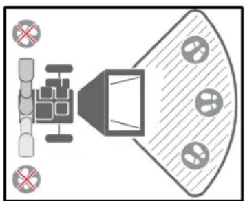
natural_image
Top-down diagram of a speaker emitting sound waves, with no text or symbols present.1.2.4. Material feeding
Only put clean materials into the machine.
Foreign materials such as dirt, sand, gravel, stones, metal fragments, etc., will damage the cutting edge of the blades. Root balls and dead wood will also dull the blades quickly.
Avoid putting pine needles, flax, and cabbage leaves into the machine; these fibrous materials can wrap around the rotor shaft and penetrate the bearing.
Avoid feeding short, thick pieces of wood into the machine; they tend to bounce and spin in the feed hopper. Feed these shorter pieces along with the longer ones. After familiarizing yourself with the machine, prune it to suit your needs.
This machine is self-feeding; do not force branches toward the blades. Let the machine advance automatically. Wait until the machine reaches maximum speed before feeding in the next load of branches.
1.2.5. Drain cleaning
Never allow processed material to accumulate in the discharge area. This can prevent proper discharge and cause backflow into the chipper hopper.
Never attempt to unclog the feed hopper or discharge chute with the engine running. Turn off the engine immediately, let the cutting disc come to a complete stop, and remove the obstructing material.
Inspect for damage and loose parts to repair or replace.
Whenever you leave the workstation or if you need to remove processed material, leaves, or debris from the machine, turn off the motor and ensure it is completely off to prevent accidental restarting. Wait until all moving parts have come to a complete stop.
Before opening the cutting disc housing, make sure the motor is off, the cutting disc is completely stopped, and the belt drive is disengaged.
1.2.6. Transfer
Move the machine at least 3 meters away from the refueling point before starting the engine.
This shredder can only be moved manually. Never attempt to tow the machine on roads, paths, or public thoroughfares.
Always stop the engine before moving the machine and be careful of sharp objects that could puncture the tires.
1.2.7. Machine use and care
Position the machine so that it will not move during maintenance, cleaning, adjustment, assembly of accessories or spare parts, or during storage.
Don't force the machine. Use the correct machine for your application. The right machine will do the job better and more safely at the speed it's designed for.
Do not modify the motor governor settings or overload it. The governor controls the maximum safe operating speed of the motor.
Do not run the engine at high speed when it is not in use.
Do not place your hands or feet near the rotating parts.
This machine has two rotating cutting blades capable of amputating hands and feet and launching objects. Keep hands and feet out of the openings while the machine is in operation. Failure to follow these safety instructions could result in serious injury or death.
Avoid contact with hot fuel, oil, exhaust fumes, and hot surfaces. Do not touch the engine or exhaust. These parts become very hot during operation and remain hot for a short time after the unit is turned off. Allow the engine to cool before performing any maintenance or adjustments.
If the machine starts making an unusual noise or vibration, turn off the engine immediately, disconnect the spark plug wire, and check the cause. Unusual noise or vibration is often a warning sign of trouble.
Use only accessories and attachments approved by the manufacturer. Otherwise, you could suffer personal injury.
Keep the engine and exhaust free of grass, leaves, excess grease, or carbon buildup to reduce the risk of fire.
Never spray the unit with water or any other liquid. Keep the handles dry, clean, and free of residue. Clean them after each use.
Observe the laws and regulations regarding the proper disposal of gasoline, oil, etc. to protect the environment.
When storing the machine, keep it out of the reach of children and do not allow it to be operated by anyone unfamiliar with the machine or these instructions. This machine can be dangerous if operated by an untrained user.
1.2.8. Maintaining your machine
Some parts of this machine are made of plastic or rubber and should be kept away from chemicals.
Never cover the machine while the exhaust is hot.
Do not alter or adjust any part of the crusher or its motor that is sealed by the manufacturer or distributor.
For maintenance of your machine, check for misalignment or jamming of moving parts.
There are broken or worn parts that could affect the machine's operation. If any damage or worn parts are identified, they must be repaired before use. Many accidents are caused by poorly maintained equipment.

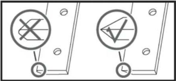
DO NOT PUT YOUR HANDS BELOW THIS LINE
1.3. Residual risks
▲ Important
Even if it complies with the relevant product safety regulations, residual risks may exist given the characteristics of the equipment and the work for which it has been designed.
Residual risks can be minimized by following safety instructions.
- You will reduce the risk of personal injury and damage to equipment if you follow these instructions and are careful.
- Failure to comply with these safety instructions may result in injury to the operator or damage to property.
- Lack of care, improper use, or failure to comply with safety regulations can result in injuries to the hands and fingers when the wedge is in motion.
Note: Even if you take preventive measures, there may be residual, non-obvious risks.
1.4. Symbols
Your machine's nameplate may display symbols. These represent important product information or operating instructions. Always keep them in good condition.
 | Please read these instructions for use carefully. |
 | Use eye protection.Use hearing protection. |
 | Use protective gloves. |
 | Wear safety footwear. |
 | Do not remove or tamper with the protective and safety devices. |
 | Do not touch hot parts during operation. Severe burns could occur. |
 | No smoking, no sparks, no flames. |
 | Never start or run the engine inside an enclosed area. |
 | Keep your hands away from all rotating parts. |
 | Do not operate on slopes with an angle greater than 20° or with the loading tip in an inclined position. |
 | Keep your hands away from moving parts. |
 | |
 | Objects thrown. |
 | Keep your hands away from the end of the hoppers while the machine is running. |
 | |
 | Exhaust fumes are dangerous and contain carbon monoxide. Remaining in the environment can cause unconsciousness and death. |
 | Always turn off the engine before starting maintenance. |
 | Keep passersby away. |
 | Do not make chips larger than 100 mm in diameter. |
 | Do not allow children to operate this machine at any time. |
 | Do not refuel while working. |
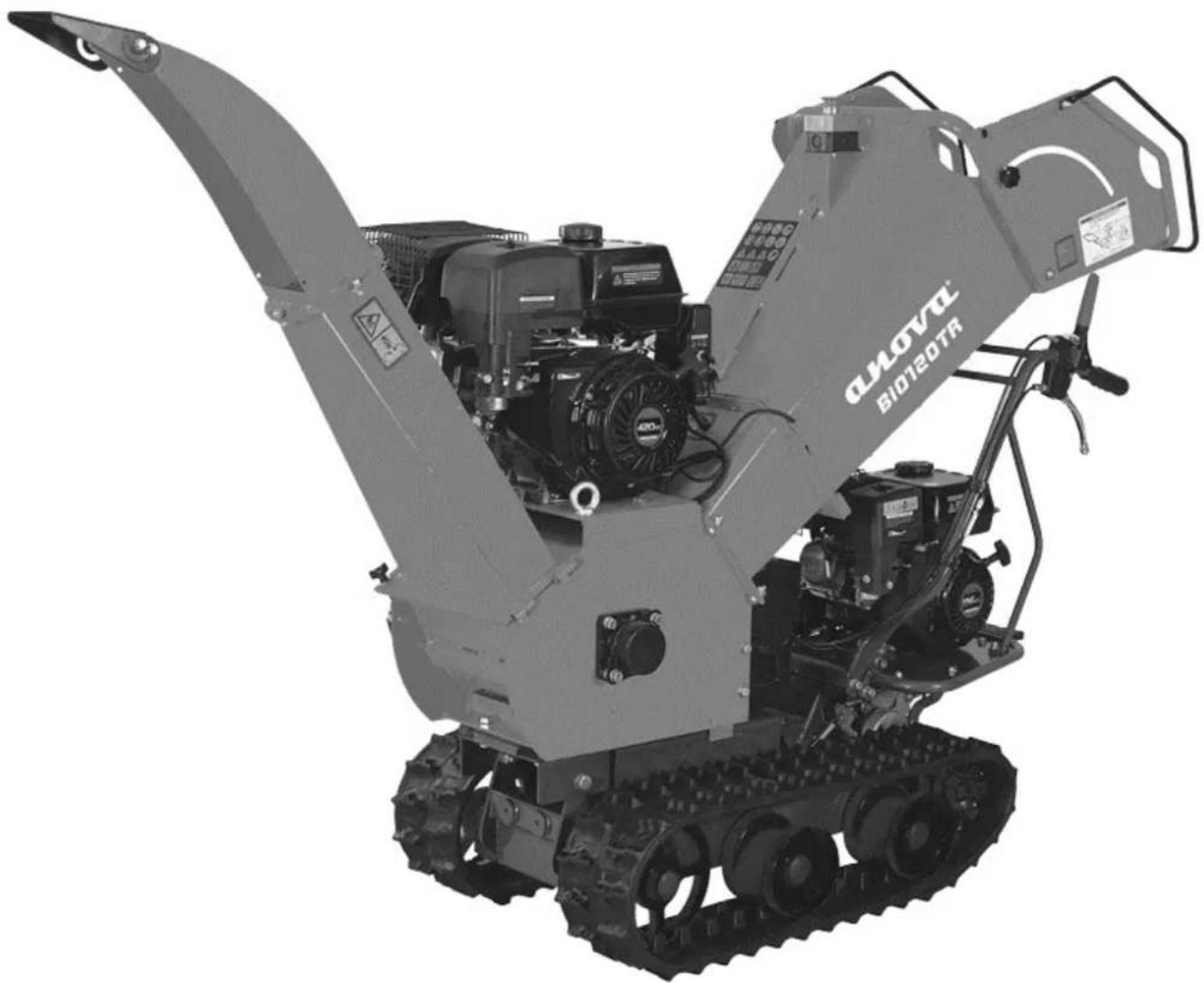
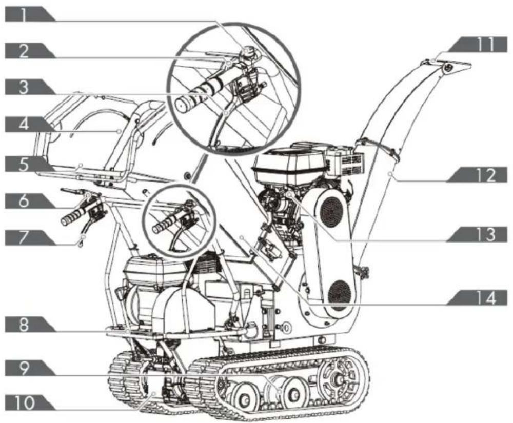
2. PRODUCT DESCRIPTION
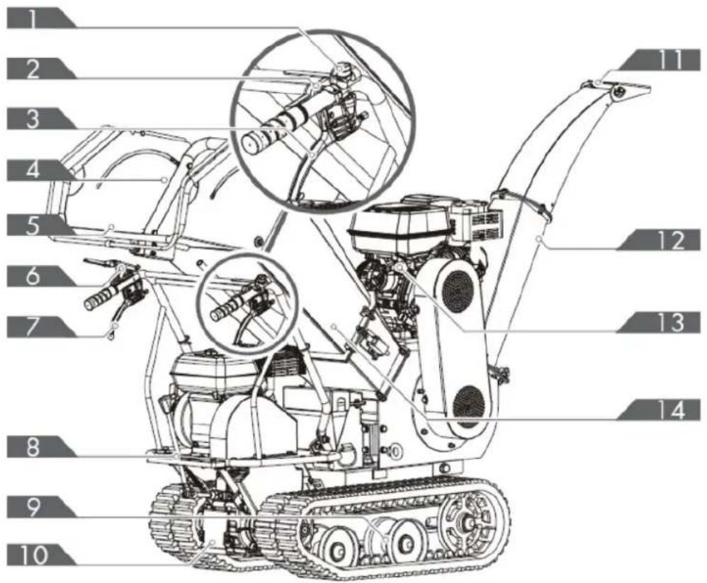
- Motor switch
- Throttle control
- Right steering lever
- Carrying handle
- Feeding tray
- Clutch control lever
-
Left steering lever
-
Gear selector lever
- Caterpillar
- Gearbox
- Deserter
- Discharge pipe
- Engine
- Feed hopper
EN
- Manual starter handle
- Engine start/stop switch
- Throttle control
- Choke control
- Fuel shut-off valve
Gear selector lever
The gear selector lever has four positions: three forward speeds and one reverse. To change gear, move the gear selector lever to the desired position. The lever locks into a notch at each gear selection.

flowchart
graph LR
    A["3"] --> B["2"]
    B --> C["1"]
    C --> D["M"]
    D --> E["R"]
▲ Important
Always release the clutch control lever before changing gears. Otherwise, the forklift will be damaged.
Slower speeds are for heavier loads, while faster speeds are for transporting lighter loads or an empty hopper. It is recommended to use a slower speed until you become familiar with the operation of the tracked wheelbarrow.
If the engine slows down under load or the tracks slip, shift the machine to a lower gear.
If the front of the machine lifts up, shift to a lower gear. If the front continues to lift, raise it by the handles.
Left/right steering lever
Operate the lever to turn left/right.
Note: Operate the steering levers only at a reduced speed
Engine start/stop switch
The motor switch has two positions.
- OFF: The engine does not start or run.
- ON: The engine starts and runs.
Manual starter handle
The handle of the manual starter is used to start the engine.
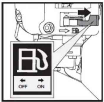
Fuel shut-off valve
The fuel shut-off valve has two positions:
- CLOSED (ED) - Use this position to perform maintenance, transport or store the unit.
- OPEN (B) - Use this position to operate the unit.
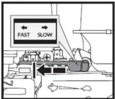
Throttle control
The throttle control regulates the engine speed and moves between the FAST and FAST positions. 🔍, SLOW 🔍 and STOP. The throttle control turns off the engine when moved to the STOP position.
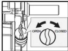
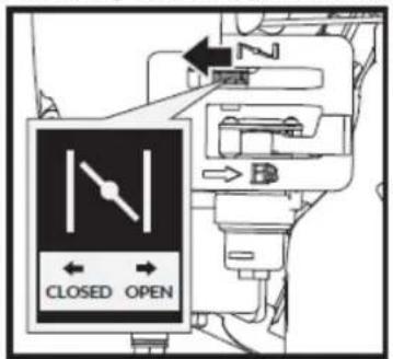
Choke control
The choke control is used to restrict the carburetor and make starting the engine easier.
The choke control moves between the CLOSED positions and OPEN. ||
Note: Never use the choke to stop the engine.
Clutch control lever
Squeeze the control lever; the clutch is engaged.
Release the lever; the clutch is disengaged.
Feed Hopper
The feed hopper is where the materials to be chipped are introduced.
Discharge Conduit
The chipped materials are discharged through this opening. The deflector can be attached to the duct.
3. TECHNICAL SPECIFICATIONS
| Characteristics | ||
| Chipper motor | 9.0kW | |
| Displacement motor | 4.0kW | |
| Chipping capacity | 120 mm | |
| Drum size | 240 mm | |
| Drum speed | 2500r/min | |
| Blades | 300 x 55 mm | |
| Opening of the feeding mouth | 295 x 155 mm | |
| Opening the feed hopper | 380 x 440 mm | |
| Sound pressure level | 96 dB(A)k=3db(A) | |
| Acoustic power level | 116 dB(A)k=3db(A) | |
| Vibration level in the handlebar grips | Left | 10.1 m/s2k=1.5 m/s2 |
| Right | 11.3 m/s2k=1.5 m/s2 | |
| Vibration value | Left | 9.014 m/s2 |
| Right | 10.59 m/s2 | |
| Weight | 309 kg | |
Note: Due to design improvements and/or changes in specifications, this manual may be modified without prior notice and without needing to change the document.
4. ASSEMBLY AND INSTRUCTIONS FOR USE
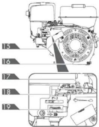
4.1. Unpacking and packaging contents
Use the screwdriver and hammer to open all the side latches.
Remove all plywood boards and remove all loose pieces from the lower pallets.
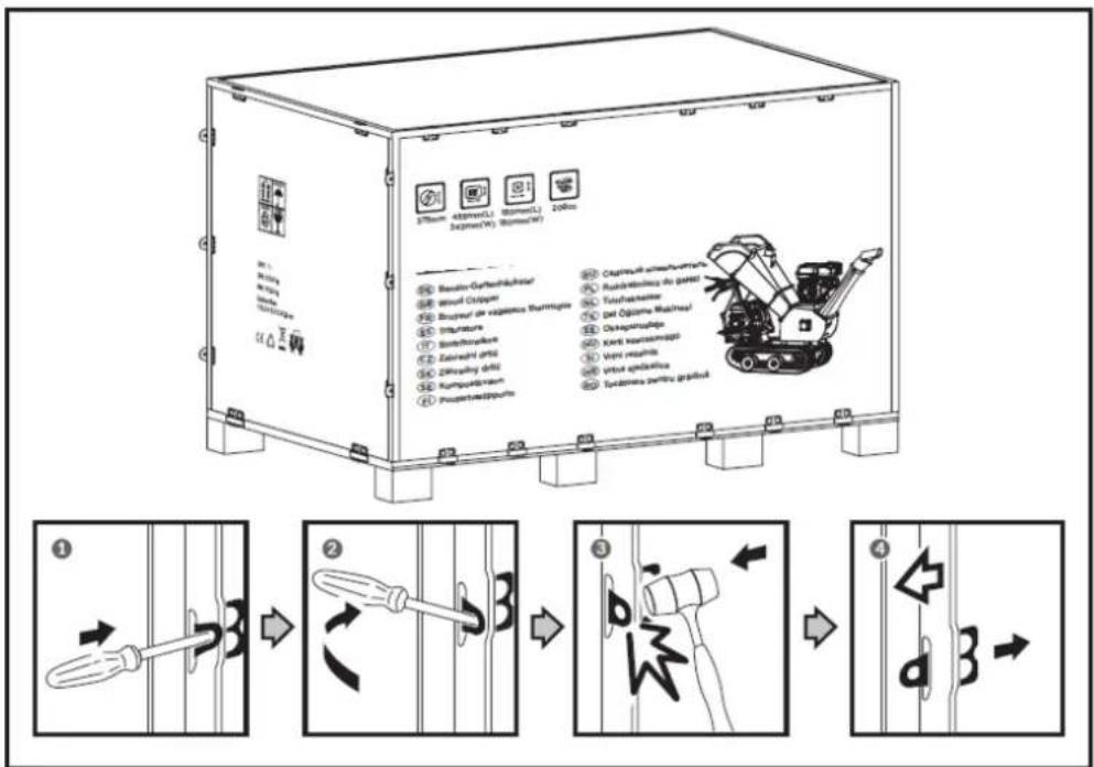
natural_image
Technical line drawing of a tracked robotic vehicle on a platform (no text or symbols)The wood chipper is delivered partially assembled and shipped in a carefully packaged box. Once all the parts are unpacked, you should have:
EN
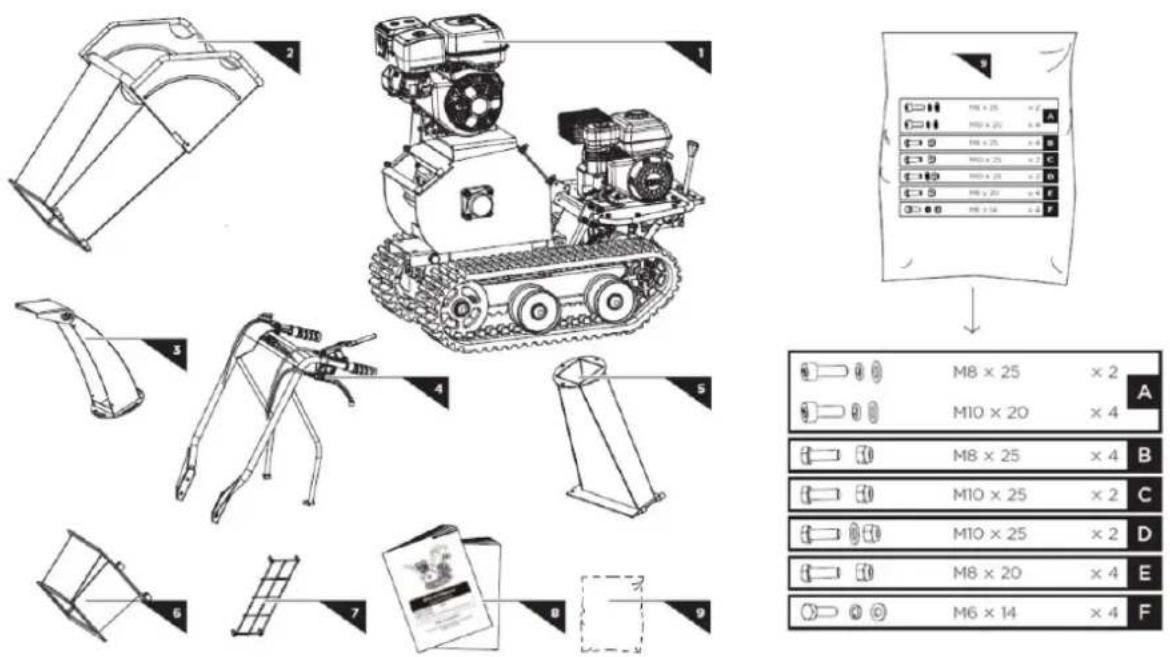
- Main machine
- Lower feed hopper
- Top feed hopper
- Protective network for the discharge outlet
- Deflector
- Operator's Manual
- Handlebar assembly
- Bag of screws (included)
- Discharge pipe
4.1. Mounting
By following the assembly instructions below, you will assemble the machine in just a few minutes.
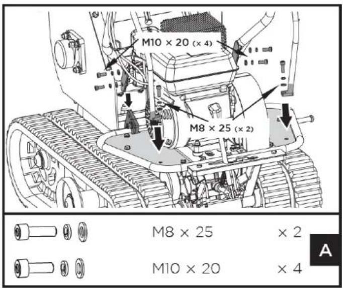
4.1.1. Handlebar assembly
- Align the handlebar holes with the mounting bracket and secure them with a spring washer, a flat washer, and an M10x20 bolt.
- Secure each handlebar bracket to the motor base with a spring washer, a flat washer, and an M8x25 hex bolt.
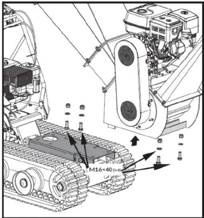
Unscrew the four M16x40 bolts, washers, and nuts that connect the chipper to the dumper base. Move the chipper back and secure it with the bolts, washers, and nuts you removed earlier.

4.1.2. Feed hopper
- Place the lower feed hopper on the machine and secure it with bolts, washers, and nuts.
EN
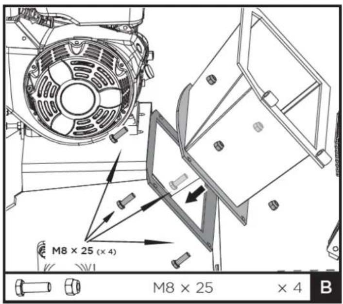
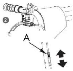
- Slide the hinge pins of the upper feed hopper into the bushings of the lower feed hopper completely, then close the upper hopper over the lower hopper and secure it with M10x25 bolts and nuts.
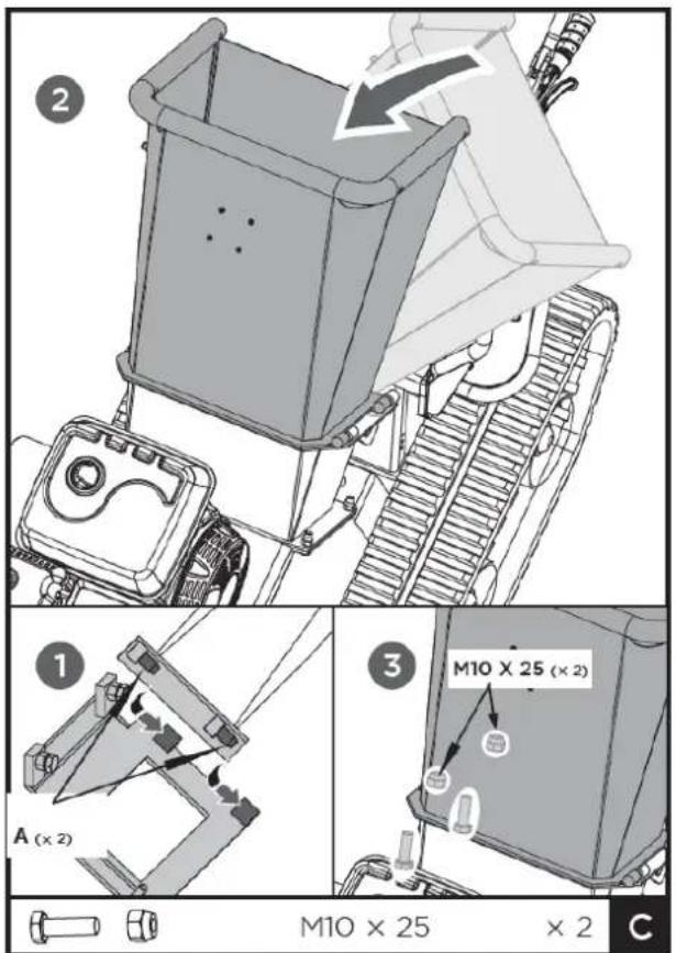
A. Hinge pin
Note: We recommend that you ask someone to help you lift the hopper into place and hold it until it is secured to the crusher.
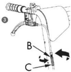
Slide the discharge chute hinge pins fully into the transmission housing weld bushings. Then, close the discharge chute onto the machine and secure it with M10x25 bolts, washers, and nuts.
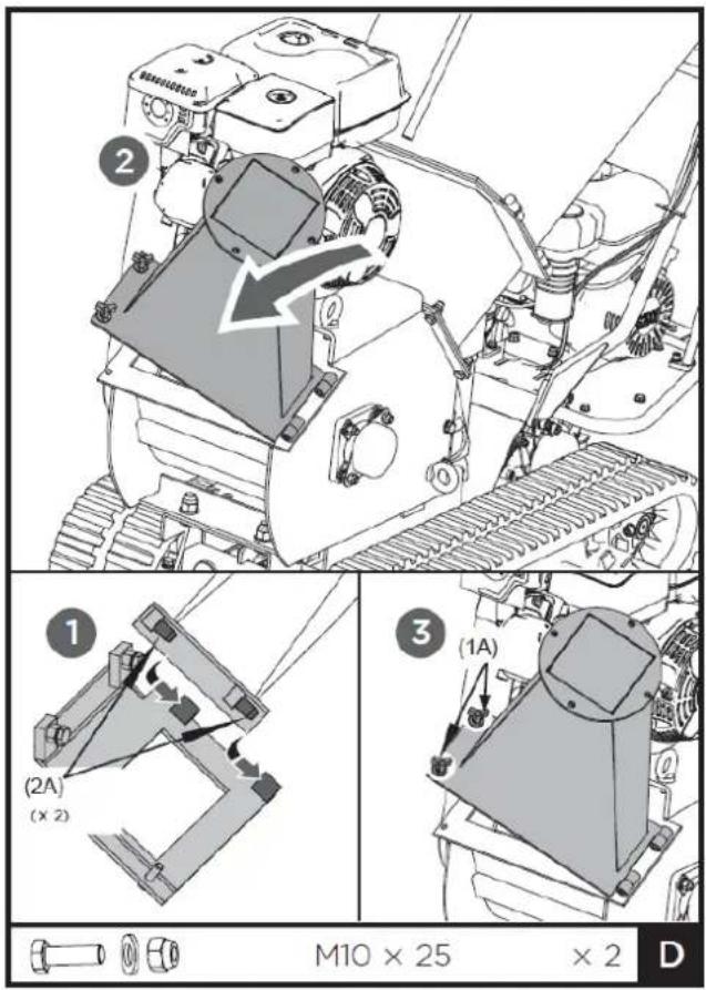
(1A). Knob
(2A). Hinge pin
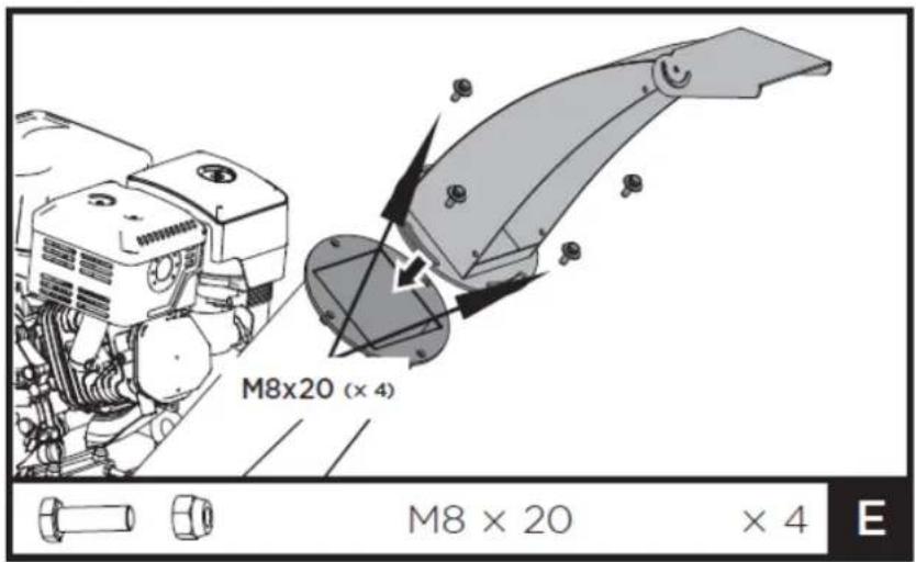
4.1.4. Deflector
Align the holes in the baffle bracket with those in the downpipe. Secure it with the bolts and nuts from the hardware kit.
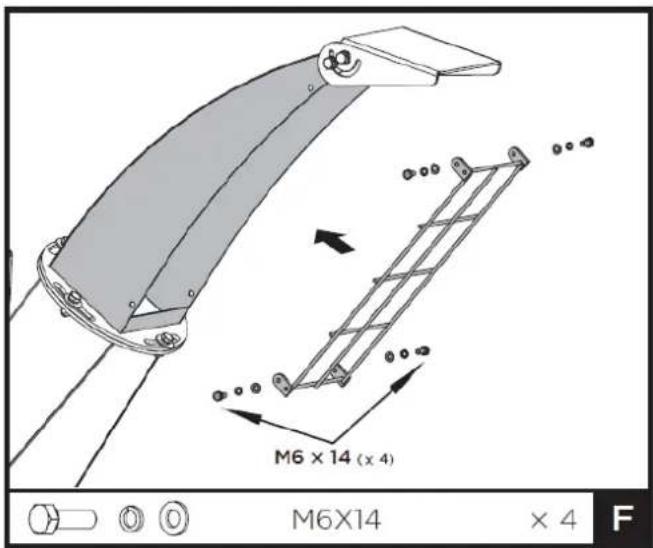
4.1.5. Protective net for discharge outlet
Place the protective net in the front opening of the upper discharge chute, align the holes and secure it with four M6x14 bolts and washers.
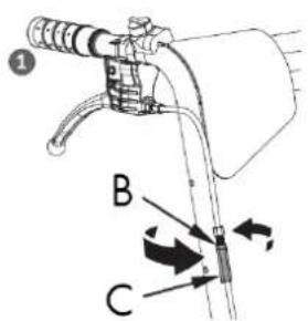
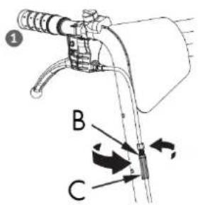
4.1.6. Emergency stop cable connection
Make sure the emergency stop cable is properly connected.
Otherwise, it could cause death or serious injury.
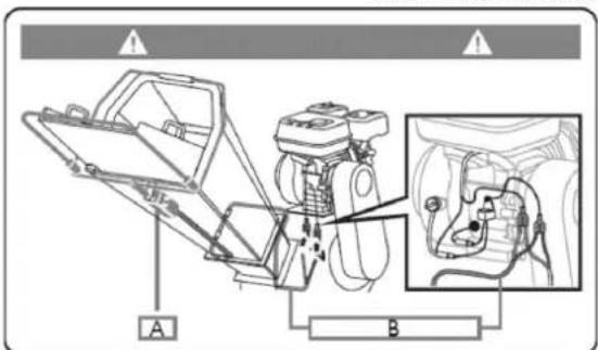
A. Emergency switch

B. Emergency stop cable
C. Emergency stop handle
4.2. Instructions for use of tracked traction
4.2.1. Add oil to the engine (displacement)
Warning
The engine is delivered without oil. Do not start the engine before adding oil. Refer to the engine manual to find out what type of oil to add.
- Make sure the tracked trolley is on a flat, level surface.
EN
- Remove the oil level plug/dipstick to add oil.
- Using a funnel, add oil to the FULL mark on the dipstick. (Refer to your engine manual for oil capacity, oil recommendation, and filler cap location.)
Warning
Do not overfill. Check the engine oil level daily and add as needed.
4.2.2. Add gasoline to the engine (displacement)
Warning
Gasoline is highly flammable and explosive. You can suffer burns or serious injury when handling this fuel. Use extreme caution when handling gasoline.
▲ Important
Fill the fuel tank outdoors, never indoors. Gasoline vapors can ignite if they accumulate in an enclosed space. An explosion could occur.
-
The engine must be turned off and allowed to cool for at least two minutes before adding fuel.
-
Remove the fuel filler cap and fill the tank. (Refer to the engine manual for fuel capacity, fuel recommendation, and cap location.)
▲ Important
Do not overfill. This equipment and/or its engine may include evaporative emissions control system components, required to comply with EPA and/or CARB regulations, which will only function properly when the fuel tank is filled to the recommended level. Overfilling can cause permanent damage to the evaporative emissions control system components. Filling to the recommended level ensures the vapor space necessary for fuel expansion. Pay close attention when filling the fuel tank to ensure you do not exceed the recommended level. Use a portable fuel container with a properly sized dispenser nozzle to fill the tank. Do not use funnels or any other device that obstructs visibility while filling the tank.
- Replace the fuel tank cap and tighten it. Always clean up any spilled fuel.
4.2.3. Engine start (displacement)
- Move the motor switch to the ON position.

- Open the fuel shut-off valve.
- Move the choke lever to the CLOSED position.
If the engine is hot, it is not necessary to close the choke.
- Move the accelerator lever slightly to FAST speed.
- Pull the manual starter until the engine starts. Return the manual starter to the starting position after each pull.
Repeat the steps as needed. Once the engine has started, place the throttle in the FAST position before operating the unit.
Warning
Rapid recoil of the starter cord will pull your hand and arm toward the engine faster than you can release it. This could cause fractures, bruises, and sprains.
4.2.4. Operation (displacement motor)
Once the engine has warmed up, move the throttle lever to increase speed.
Engage the desired gear and slowly squeeze the clutch lever. If the gear does not engage immediately, slowly release the clutch lever and try again. The electric forklift will then begin to move.
The electric forklift has the steering levers on the handlebars, making it extremely easy to operate. To turn right or left, simply pull the corresponding lever.
EN
The steering sensitivity increases proportionally to the machine's speed and load. With the machine empty, only light pressure on the lever is needed to turn. When the machine is fully loaded, more pressure is required.
The electric forklift has a maximum load capacity of 300 kg. However, it is recommended to assess the load and adjust it according to the terrain where the machine will be used.
Therefore, it is recommended to cover uneven or rough terrain in a low gear and to exercise extreme caution. In such situations, the machine should be kept in a low gear throughout the journey.
Avoid sharp turns and frequent changes of direction when driving on rough and hard terrain with sharp and uneven spots with a high degree of friction.
Although the unit has rubber tracks, take care when working in adverse weather conditions (ice, heavy rain and snow) or on terrain that may destabilize the wheelbarrow.
Please note that, being a tracked vehicle, it is subject to considerable pitching when going over bumps, holes, and steps.
When you release the clutch control lever, the machine stops and brakes automatically.
If the machine stops on a steep slope, a wedge should be placed against one of the tracks.
4.2.5. Slow motion
Set the throttle lever to the SLOW position to reduce engine strain when not in use. Reducing engine speed will prolong its life, save fuel, and reduce noise levels.
4.2.6. To stop the engine
To stop the engine in an emergency, simply turn the engine switch to the off position. Under normal conditions, follow this procedure:
- Move the accelerator lever to the SLOW position ( ).
- Let the engine idle for one or two minutes.
- Turn the engine switch to the OFF position.
- Turn the fuel valve lever to the OFF position (B).
Warning
Stopping the engine suddenly at high speed under heavy load is not recommended. It could damage the engine.
Do not move the choke to the CLOSED position to stop the engine. This could cause a backfire or engine damage.
4.3. Crushing operation
The engine is delivered without oil. Do not start the engine before adding oil.
4.3.1. Engine start (crusher)
To start the chipper motor, use the same procedure as for the shredder motor.
4.3.2. Operation
Once the engine has warmed up, pull the throttle lever to accelerate.
As the motor slowly increases its speed to maximum, gradually and slowly pull the belt tensioner lever all the way in to engage the belt drive. This must be done slowly to allow the cutting disc to gain speed; otherwise, the motor will stall due to the high inertia of the cutting disc.
The chipper can process a wide variety of dry or green organic materials, such as branches, stems, vines, leaves, roots, and other plant matter. The maximum capacity is branches up to 7.6 cm in diameter; this may vary depending on the type and hardness of the wood.
Rotating the branch as you insert it into the machine will improve performance.
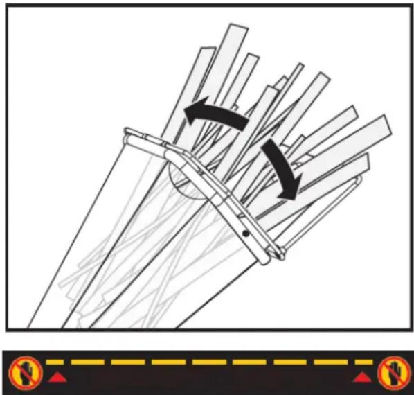
natural_image
Diagram of a mechanical assembly with directional arrows indicating motion, no text or symbols presentNO HANDS ALLOWED BELOW THIS LINE
Feed the branches in with the cut end first, leaving the top leafy. This helps guide the branch through the feed hopper and reduces the spinning and bouncing of small pieces as they are fed back in. Some side branches may require pre-cutting to feed more efficiently.
It is always advisable to process freshly cut materials, as wood branches harden considerably, become elastic when drying, and can cause blades to dull more quickly.
While operating the machine, keep a wooden stick approximately 2.5 cm in diameter and 60 cm long handy. This stick will be useful for feeding short materials, including those with a lot of weeds and leaves, and for keeping the feed hopper clear.
Do not force material into the machine. If chipping is not working properly, the chipper blades may need sharpening or replacement, or the gap between the blades and the wear plate may need adjusting.
Do not overload the machine by putting too much material into the feed hopper at once.
If you hear the motor speed decrease, immediately stop feeding the material. Do not resume feeding until the motor has returned to full speed.
The wood chipper/shredder can become clogged with soft, wet, or fibrous materials. However, if you feed soft materials intermittently, such as branches, there shouldn't be a problem, as the chipper/shredder tends to clear any residue left in the machine.
EN
If any fibrous material becomes wrapped around the rotor shaft, remove it before it penetrates the bearing.
If the wood chipper stalls due to overload or obstruction, turn off the motor and wait until the cutting disc comes to a complete stop and the belt drive disengages. Allow the motor to cool completely and then turn it off. Open the housing cover to clean and remove all materials.
Close the housing cover, turn on the motor, and restart the machine to resume operation.
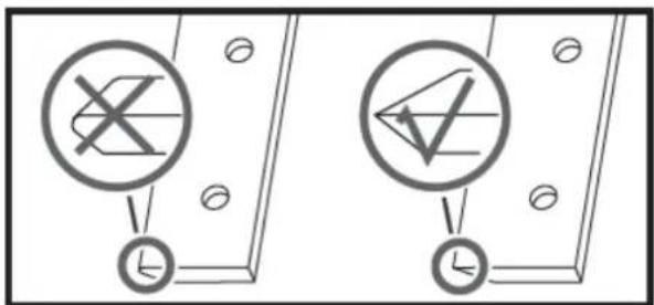
As the discharge material accumulates, move the chipper away from the pile. This will prevent material from building up in the discharge chute. Do not place the deflector vertically, as this will reduce airflow, impeding discharge and causing blockages.
Warning
- Make sure the machine is level and stable to avoid unnecessary vibrations.
- Do not operate it on concrete or any other hard surface.
- The engine is equipped with an oil alert and will not start if the oil level in the crankcase is too low. It may also stall if operated on a steep incline.
- To turn off the machine, move the throttle lever to idle, turn the engine switch to the off position and it will gradually stop.
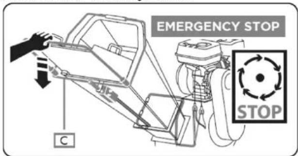
4.3.3. Emergency stop
Ensure the emergency stop switch is functioning correctly before each use. Failure to do so could result in serious injury or death. Note that the emergency stop cable must be routed along the left side of the hopper, as viewed from above.
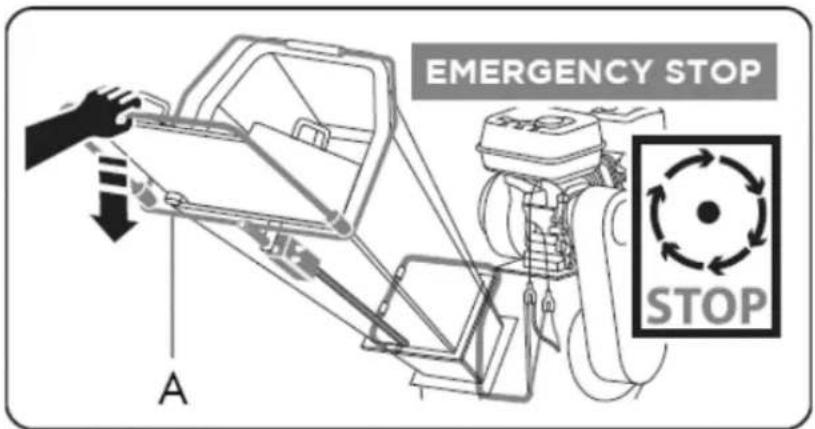
A. Emergency stop handle
4.3.4. Slow motion
Set the throttle lever to the SLOW position to reduce engine strain when not idling. Reducing engine speed will help prolong its life, save fuel, and reduce noise levels.
4.3.5. Engine stop
To turn off the engine in case of emergency, simply turn the engine switch to the OFF position.
Under normal conditions, follow the procedure below:
- Move the accelerator lever to the SLOW position ( ).
- Leave the engine idling for one or two minutes.
- Turn the engine switch to the OFF position.
- Turn the fuel valve lever to the OFF position (ED).
Stopping the engine suddenly at high speed under heavy load is not recommended. It could damage the engine.
Do not move the choke to the CLOSED position to stop the engine. This could cause a backfire or engine damage.
Wait until the machine has come to a complete stop. Allow the engine to cool completely. Remove the spark plug from the engine. Then, clean the inside of the machine and its exhaust chute.
5. MAINTENANCE AND STORAGE
Proper maintenance is essential for safe operation and to minimize potential machine problems. Follow the recommendations and inspection and maintenance schedules in this manual.
Warning
Improper maintenance, failure to correct a problem before operation, or the use of non-manufacturer-approved replacement parts can cause malfunction and serious personal injury. Always use appropriate PPE when performing adjustments or repairs.
5.1. Track traction maintenance
Maintaining your tracked product will ensure a long service life for the machine and its components.
5.1.1. Preventive maintenance
- Turn off the engine and deactivate all control levers. The engine must be cold.
- Keep the engine throttle lever in the SLOW position and disconnect the spark plug wire and secure it.
- Inspect the overall condition of the forklift. Check for loose screws, misaligned or stuck moving parts, cracked or broken parts, or any other condition that could affect its safe operation.
- Use a soft brush, vacuum cleaner, or compressed air to remove all contaminants from the machine. Then, use high-quality light oil to lubricate all moving parts.
- Check the spark plug wire regularly for signs of wear and replace it when necessary.
Warning
Never use a pressure washer to clean your unit. Water can penetrate tight spaces in the machine and its transmission, damaging spindles, gears, bearings, or the motor. Using a pressure washer will reduce its lifespan and serviceability.
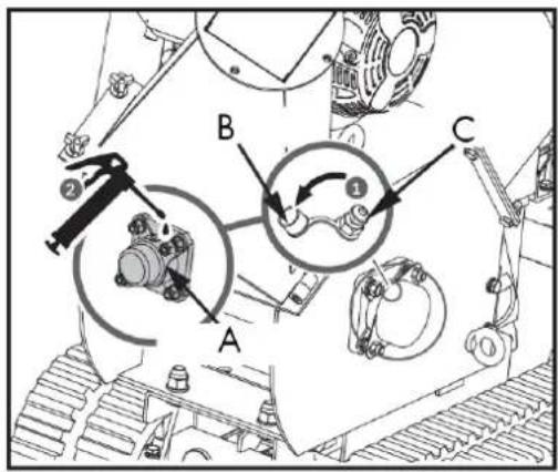
5.1.2. Clutch adjustment
When the clutch begins to show wear, the reach of the lever widens, making it difficult to access. Follow these steps to return the clutch lever to its original position.
- Loosen the lock nut by turning it counterclockwise with a 10mm wrench.
- Tighten or loosen the cable by turning the cable adjusting nut clockwise or counterclockwise with a 10mm wrench until the desired tightness is reached.
- Once adjusted, replace the lock nut against the handle to secure the cable.
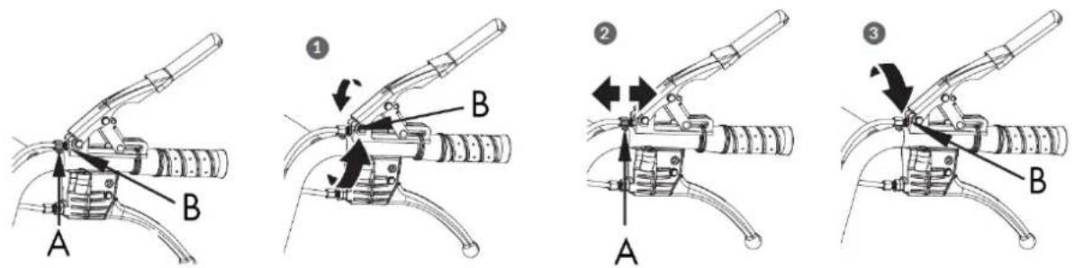
A. Adjustment nut B. Locknut
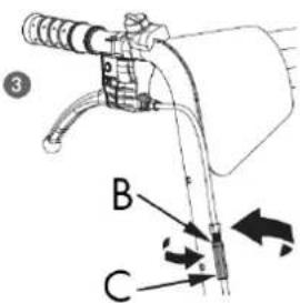
5.1.3. Steering adjustment
If you are having difficulty controlling the direction, follow these steps to adjust the cable tension.
- Loosen the lock nut by turning it counterclockwise with a 10mm wrench.
- Tighten or loosen the cable by turning the adjusting nut clockwise or counterclockwise with a 10mm wrench until the desired tension is reached.
- Once the tension is adjusted, replace the lock nut against the handle to secure the cable.
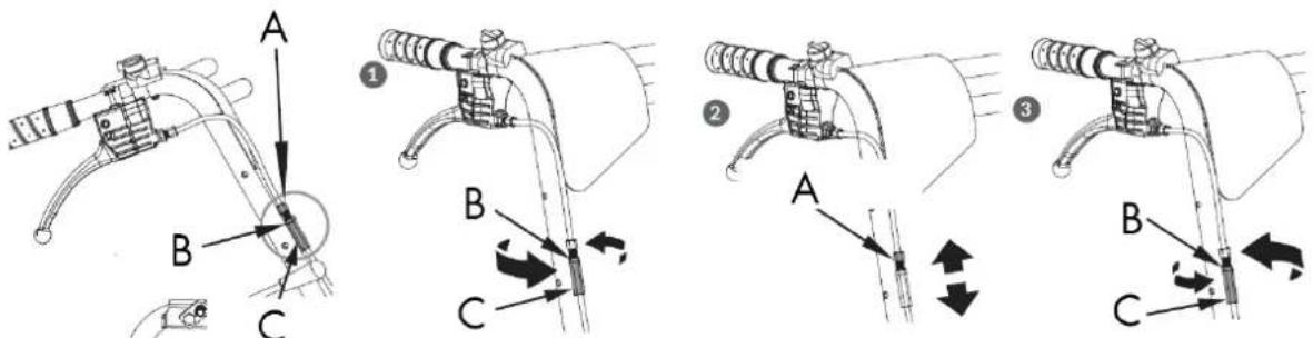
A. Adjustment nut
B. Locknut
C. Locknut.
If the previous adjustment does not create enough tension on the cable, follow the steps below:
- Loosen the lock nut by turning it counterclockwise with a 12mm wrench.
- Tighten or loosen the cable by turning the adjusting nut clockwise or counterclockwise with a 10mm wrench until the desired tightness is reached.
- Once the tightening is adjusted, replace the lock nut against the handle to secure the cable.
EN
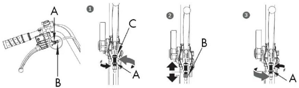
A. Locknut
B. Adjustment nut C. Locknut
5.1.4. Drive belt replacement
Remove the strap covers as shown and pull out the strap.
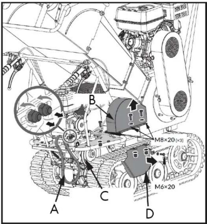
A. Transmission belt
B. Strap cover
C. Gearbox pulley
D. Belt cover for gearbox pulley
Warning
You may need to loosen the belt guide bracket and slide it back before removing the belt.
5.1.5. Lubrication
General lubrication
Lightly lubricate all moving parts of the machine at the end of the season or every 25 hours of operation.
Gearbox lubrication
EN
The gearbox comes pre-lubricated and sealed from the factory. Unless there is evidence of leaks or maintenance has been performed, no additional lubrication is required for up to 50 hours of use.
After the first 50 hours of use, change all the gear oil.
The capacity is 1.5 L.
For future use, check the oil level every 50 hours of operation. If no oil comes out when you remove the oil level plug, add oil and then replace the plug.
GL-5 or GL-6 gear oil, SAE80W-90, is recommended. Do not use synthetic oil.
When changing the gear oil, the engine should be stopped and still warm. Unscrew the filter cap and the drain plug. Once the oil has drained, replace the drain plug, refill with new oil, and replace the filter cap.
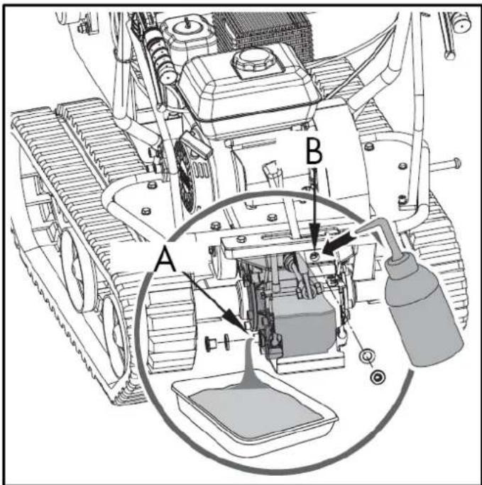
A. Oil filling B. Oil outlet
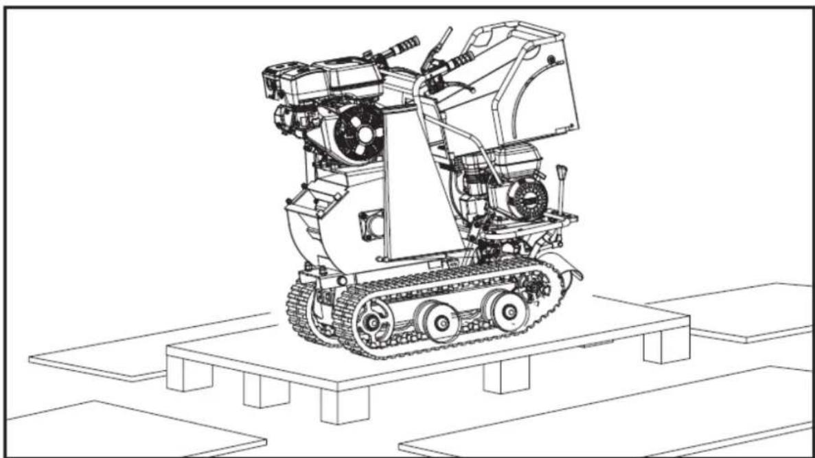
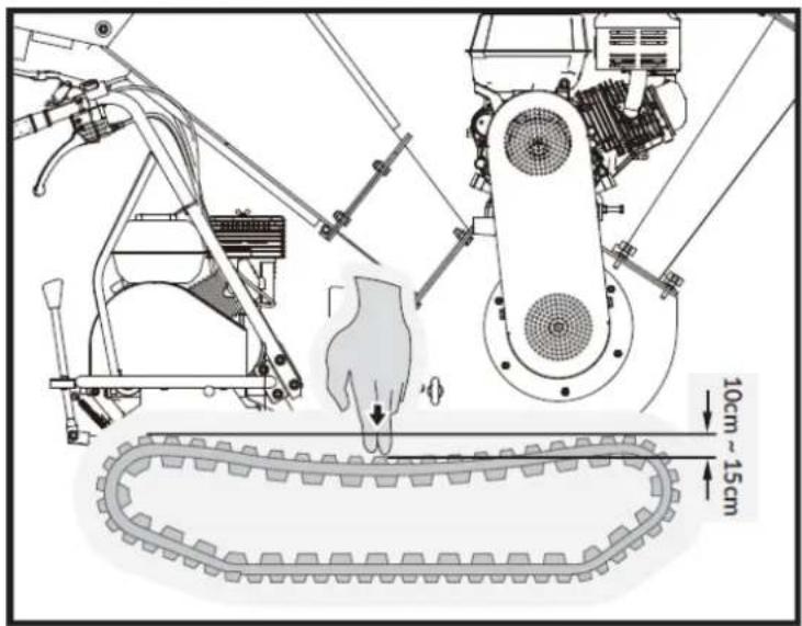
5.1.6. Track tensioning
With use, tracks tend to loosen. When operating with loose tracks, they tend to slip over the drive sprocket, causing it to jump out of its housing, which accelerates wear.
To check the track tension, proceed as follows:
- Place the machine on a flat surface with compacted soil, or on asphalt or paving stones.
- Lift the machine and place it on blocks or supports suitable for its weight, so that the tracks are approximately 10 cm from the ground.
- Measure the caterpillar's midline from the horizontal line. The reading should not exceed 10-15 cm.
EN
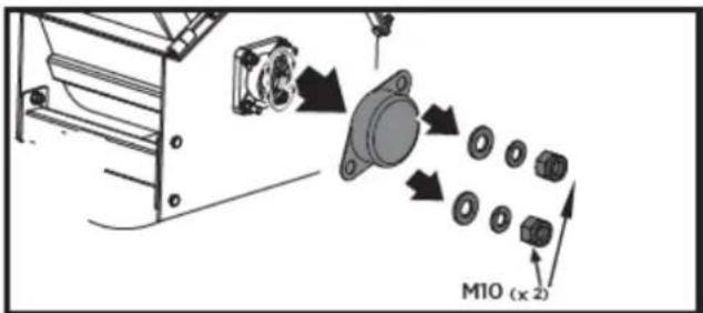
5.1.7. Rail replacement
Check the condition of the rails regularly. If any are cracked or worn, replace them as soon as possible.
- Remove the entire crusher.
- Remove the mounting seat.
EN
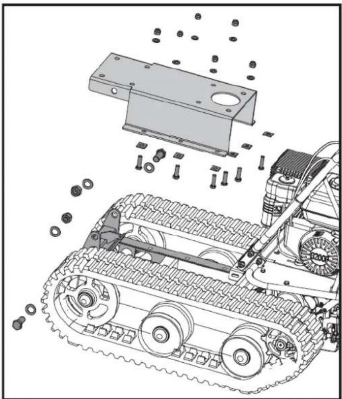
natural_image
Technical illustration of a tracked vehicle with mechanical components and bolts, no visible text or symbols- Loosen the adjusting bolts and pull the flywheel shaft towards the engine; then the track will loosen.
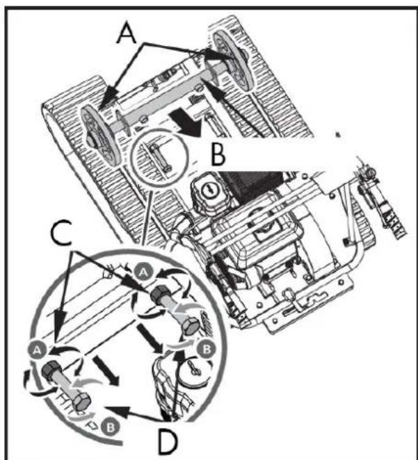
A. Steering wheel
B. Steering wheel axis
C. Locknut
D. Adjustment bolt
- Get the whole track out.
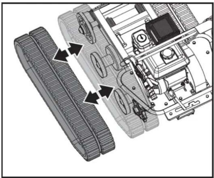
natural_image
Technical diagram of a robotic vehicle showing track and chassis components with directional arrows indicating motion (no text or labels)When removing or installing the tracks, be careful not to trap your fingers between the track and the pulley.
- After replacing the track, reassemble the machine in reverse order.
5.1.8. Engine maintenance
Refer to the engine manual included with your unit for engine maintenance information. The engine manual provides detailed information and a maintenance schedule for performing the necessary tasks.
5.2. Crusher maintenance
Maintaining your crusher will ensure a long lifespan for the machine and its components.
5.2.1. Preventive maintenance
- Turn off the engine. The engine must be cold.
- Keep the engine throttle lever in the SLOW position and disconnect the spark plug wire and secure it.
- Inspect the overall condition of the chipper.
Check for loose screws, misaligned or stuck moving parts, cracked or broken parts, or any other condition that may affect its safe operation. - Remove all debris from the chipper using a soft brush, a vacuum cleaner, or compressed air. Then, use a high-quality, light machine oil to lubricate all moving parts.
- Replace the spark plug wire.
Warning
Never use a pressure washer to clean your wood chipper. Water can penetrate tight spaces inside the unit and damage the spindles, pulleys, bearings, or motor.
Turn off the engine, wait until all moving parts have come to a complete stop, remove the spark plug wire and wait five minutes before performing any maintenance on the chipper.
5.2.2. Regular maintenance checklist
The service intervals shown are the maximum under normal operating conditions. Increase the frequency in dusty or dirty conditions.
| Procedure | Before each use | After the first 15 minutes | Every 25 hours | Every 100 hours |
| Check the engine oil level | ▲ | ▲ | ||
| Check the overall condition of the | ▲ | ▲ | ||
| Check the blades | ▲ | ▲ | ||
| Check straps | ▲ | ▲ | ||
| Check the switch emergency stop | ▲ | |||
| Check tire pressure | ▲ | |||
| Clean the exterior of the engine and the cooling system | ▲ | |||
| Change the engine oil | ▲ | |||
| Replace the air filter | ▲ | |||
| Replace the spark plug | ▲ |
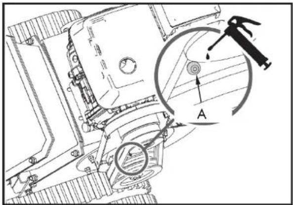
There are two bearings, one outer and one inner to the housing. The bearings are greased when new, but it is recommended to grease them after a couple of hours of use. One or two applications are sufficient. Be careful not to over-grease, as excessive lubrication can damage the bearings.
Lubrication of the outer bearing
- Open the plastic oil cap.
- Grease the outer bearing through the fill hole.
- Close the plastic oil cap.
A. Outer bearing
B. Plastic oil cap
C. Filling hole
5.2.3. Grease the inner bearing
- Unscrew the four M6x2 bolts and open the belt cover.
EN
- Grease the inner bearing.
A. Inner bearing
If the machine's cutting disc strikes a foreign object, or if the machine starts making unusual noises or vibrating excessively, turn off the motor immediately. Let the cutting disc come to a complete stop. Turn off the motor to prevent accidental restarting.
Next, perform the following steps:
- Inspect for damage.
- Repair or replace damaged parts.
- Check for loose parts and tighten them to ensure safe operation.
- If the cutting disc gets stuck on branches, open the bearing cover and turn the disc shaft with a wrench to rotate it.
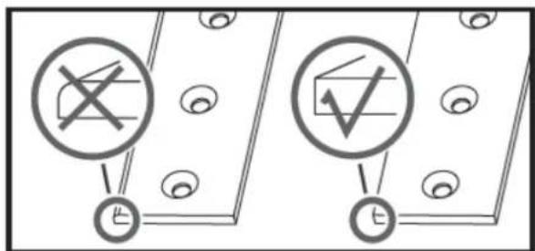
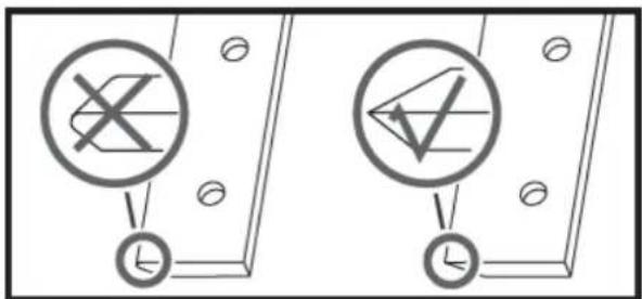
5.2.4. Inspection of blades and wear plate
Regular inspection of the blade sharpness and wear plate edge will ensure your chipper/shredder operates at peak efficiency. Using dull blades or a rounded wear plate will reduce performance and cause excessive vibration, which will damage the machine and make chipping more difficult for the operator.
5.2.5. Blade removal and replacement
This shredder is equipped with two blades mounted on the cutting disc.
When the blades become dull or show visible nicks, the machine loses its self-feeding capability and the material must be pushed in. Often, the material comes out in long strips. The blade is hardened and reversible. The cutting edges typically last a long time. When the edge is rounded, it can be reversed. If both edges are worn, the blades must be replaced.
To replace the blades, follow these steps:
- Remove the two M8 nuts and open the feed hopper.
- Remove the bolts that secure the blade.
natural_image
Technical line drawing of a mechanical device with gears and components (no text or symbols)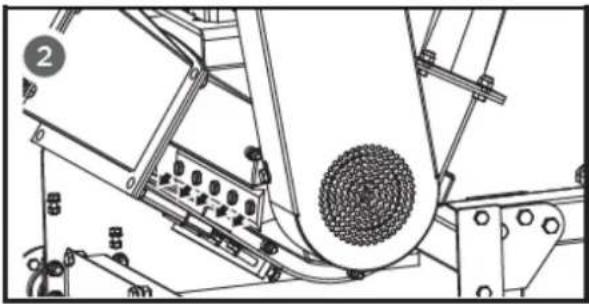
natural_image
Technical line drawing of a mechanical assembly with no visible text or symbolsWarning
Be careful and wear gloves when working near knives.
- Remove any dull or damaged blades and visually inspect the cutter disc groove and mounting area. Ensure they are clean and that the positioning blades are aligned with the cutter disc. Reinstall new or sharpened blades with the cutting edges facing up.
Warning
If the surface of the cutting disc is not cleaned properly and the blades are not mounted flush on the cutting disc, they could crack when the hardware is tightened.
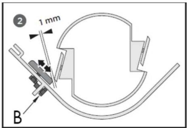
5.2.6. Removal and replacement of the wear plate
The wear plate is case-hardened and reversible. Its cutting edges typically last a long time. When the edge becomes rounded, it can be reversed. The wear plate cannot be resharpened; it will lose its hardness due to the case hardening process. When both cutting edges are worn, the wear plate must be replaced.
-
Remove the feed hopper.
-
Remove the locknuts and bolts that secure the wear plate to the chipper assembly, and then remove the wear plate.
A. Wear plate
- Install the new wear plate and secure it with the bolts and locknuts.
The gap between the blade and the wear plate must be adjusted each time the latter is removed.
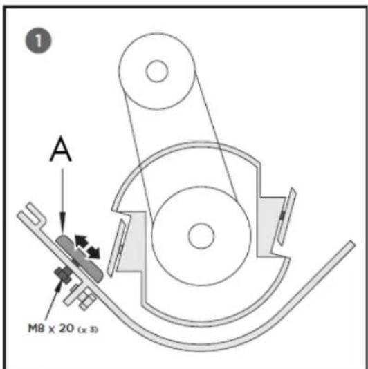
A. Wear plate
B. Adjustment bolt (x1)
Note: The wear plate can be adjusted using the mounting slots. Loosen the bolts securing it and slide it through the long holes. Then, tighten the bolts once the proper clearance is reached.
5.2.7. Tighten the wear plate bolts
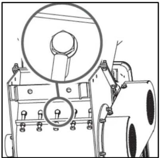
natural_image
Technical line drawing of a mechanical device with a magnified inset showing a bolt and nut (no text or symbols)If the wear plate is not properly adjusted, excessive vibration will occur when chopping, and the blade will appear dull. If there is insufficient clearance, the blade edges may touch the wear plate due to deflection when cutting thick branches, damaging the cutting edge.
Excessive clearance will allow small branches and fibrous materials to be dragged along without being cut.
Warning
After performing maintenance or adjustments, rotate the cutting disc with a rod and carefully observe and listen for any unusual noises, clicking, or vibrations. If you detect any of these, inspect the machine for damage or loose parts and repair, replace, or tighten them before starting it up.
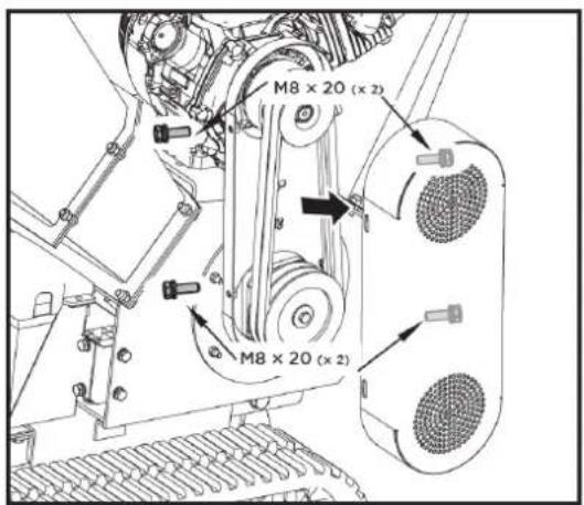
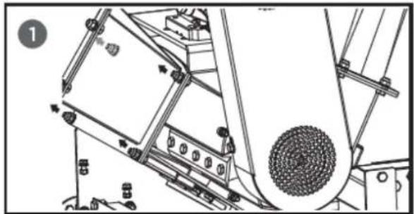
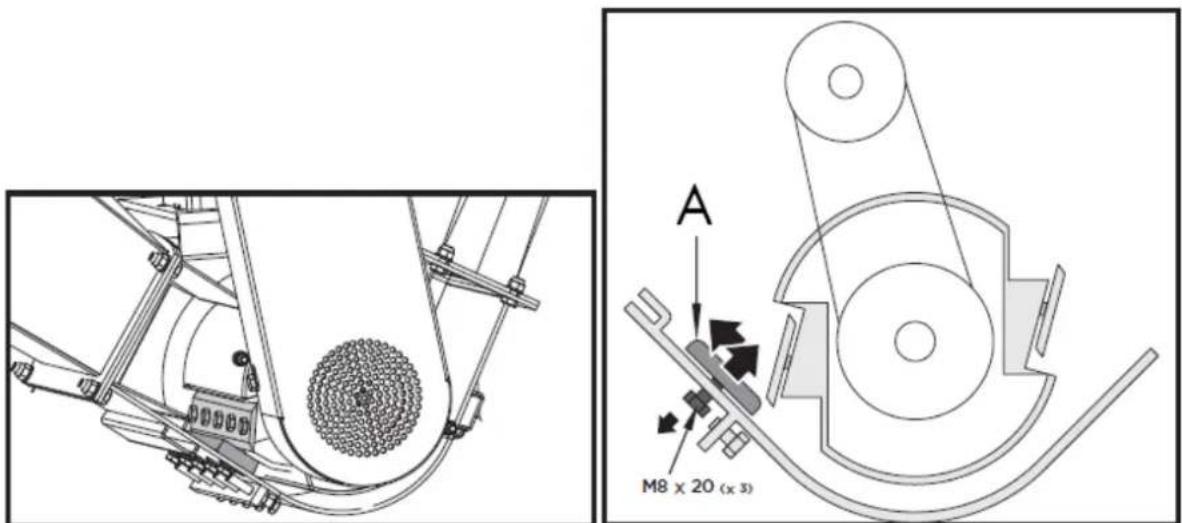
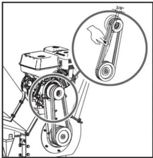
5.2.8. Checking the V-belt
- Unscrew the four M8x20 bolts and open the belt cover.
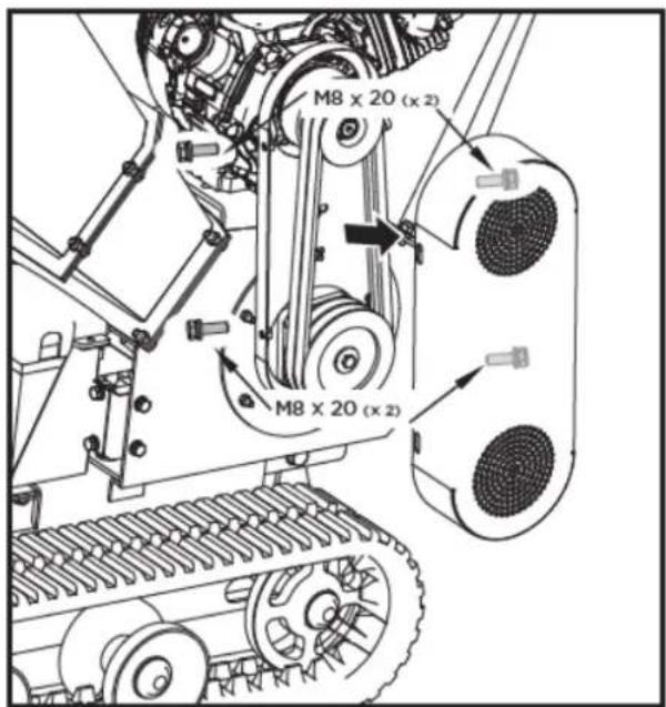
Warning
When adjusting the belt(s), make sure the motor pulley is aligned with the cutting disc pulley.
-
Check the condition of the V-belts. If any are cracked, worn, or glazed, they must be replaced.
-
Check the tension of the V-belts by tightening them in the center. The normal notch on each side should be approximately 9.5 mm (3/8 inch) with moderate pressure from your thumb or forefinger.
natural_image
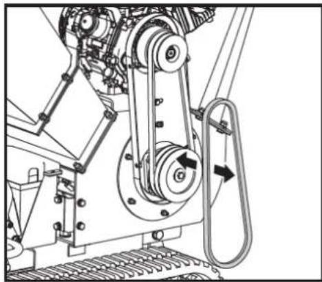
Mechanical assembly diagram showing a pump and belt drive system with magnified inset of hand pulling a pulley (no text or symbols)5.2.9. V-belt tension
Proper belt tension is essential for optimal performance. Correct adjustment ensures a long belt lifespan. Excessive or insufficient tension will lead to premature belt failure.
-
Turn off the engine. The engine must be cold.
-
Remove the strap cover.
-
Loosen the four bolts securing the engine. Loosen the two limit bolts at the front of the engine base. Then, move the engine to the belt loosening or tightening position.
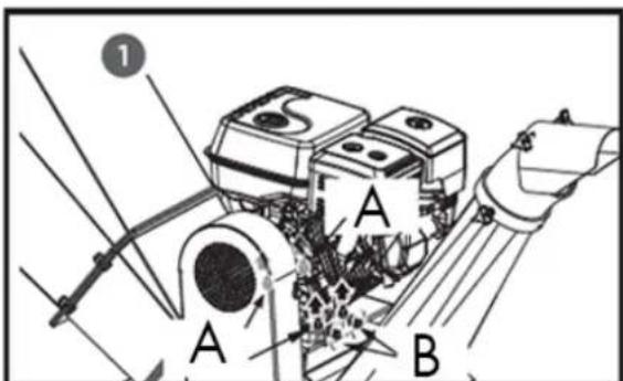
A. Adjustment bolts
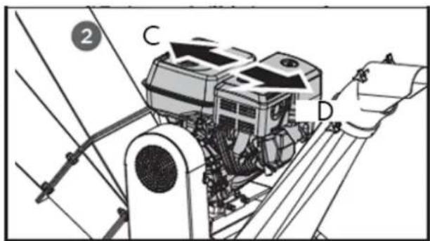
B. Limit bolts
C. Tight
D. Loose
- When the V-belt tension is correct, tighten the four adjusting bolts and the two limit bolts.
If the tension on the V-belt is excessive, loosen it in the opposite direction by moving the two M12 adjusting nuts upwards and adjusting the sleeve between them.
EN
- Check the V-belt tension by tightening it in the center. The normal notch on each side should be approximately 9.5 mm (3/8 inch) with moderate pressure from your thumb or forefinger.
5.2.10. V-belt replacement
Warning
Both V-belts should be replaced at the same time, as they wear evenly with normal use.
- Unscrew the four M8x20 bolts and open the belt cover.
- Loosen the engine and move it in the direction of belt loosening.
- Remove the damaged belt and install the new one.
natural_image
Mechanical assembly diagram showing a belt drive mechanism with pulleys and rotating components (no text or labels)- Check the V-belt tension by tightening it in the center. The normal notch on each side should be approximately 9.5 mm (3/8 inch) with moderate pressure from your thumb or forefinger.
- After adjusting the belt tension, secure the motor.
Warning
When removing or installing the drive belt(s), be careful not to trap your fingers between the belt and the pulley.
5.3. Storage
If your chipper will not be used for more than 30 days, follow the steps below to prepare it for storage:
-
Completely drain the fuel tank. Old fuel has a high gum content and can clog the carburetor and restrict fuel flow.
-
Start the engine and let it run until it stalls. This ensures that no fuel remains in the carburetor and helps prevent the formation of deposits inside, which can damage the engine.
-
Drain the engine oil while it is still warm. Refill with new oil of the grade recommended in the engine manual.
-
Let the engine cool. Remove the spark plug and add 60 ml of high-quality SAE-30 engine oil to the cylinder. Slowly pull the starter cord to distribute the oil. Replace the spark plug.
Warning
Remove the spark plug and drain all the oil from the cylinder before attempting to start the unit after storing it.
- Use clean cloths to wipe the outside of the chipper and keep the ventilation grilles free of obstructions.
Warning
Do not use harsh detergents or petroleum-based cleaners to clean the plastic parts. The chemicals can damage the plastic.
- Store the chipper upright in a clean, dry, and well-ventilated place.
Warning
Do not store the fuel-filled chipper in an unventilated area where fuel vapors can reach flames, sparks, pilot lights, or any other ignition source. Use only approved fuel containers.
6. TROUBLESHOOTING
6.1. Troubleshooting
If you experience any of the following problems during use, resolve them as described below.
Note: If you cannot resolve the product issues, please contact your official distributor.
Note: If you have any questions or problems persist after performing the above operations, please contact your official distributor.
| Problem | Possible cause | Solution |
| The engine won't start. | 1. The spark plug wire is disconnected.2. There is no fuel or the fuel is in poor condition.3. The engine and/or fuel valve are not in the ON position.4. The choke lever is not in the CLOSE position.5. The fuel line is blocked.6. The spark plug is dirty.7. The engine has stalled.8. The belt tension lever is activated. | 1. Firmly connect the spark plug wire to the spark plug.2. Fill with clean, new gasoline.3. The engine and fuel valve must be in the ON position.4. The choke lever must be in the CLOSE position for a cold start.5. Clean the fuel line.6. Clean, adjust the gap, or replace.7. Wait a few minutes before restarting, but do not prime the engine.8. Unhook the belt tension lever. |
| The engine runs erratically. | 1. The spark plug wire is loose.2. The unit operates with the choke lever in the CLOSED position.3. Blocked fuel line or fuel in poor condition.4. Obstructed ventilation.5. Water or dirt in the fuel system.6. Dirty air filter.7. Incorrect carburetor adjustment. | 1. Connect and tighten the spark plug wire2. Move the choke lever to the OPEN position3. Clean the fuel line. Fill the tank with clean, fresh gasoline.4. Clean the vent5. Empty the tank. Refill with fresh fuel.6. Clean or replace the air filter7. Consult the engine manual |
| The engine overheats | 1. Low engine oil level2. Dirty air filter3. Restricted airflow4. Poorly adjusted carburetor | 1. Fill the crankcase with the appropriate oil.2. Clean the air filter.3. Remove the casing and clean it.4. Consult the engine manual. |
| The chipping action seems too slow, the drum jams, or no material is discharged when the motor is running. | 1. The motor speed is too slow, causing the belt to slip.2. The drive belt is loose or damaged.3. The blades are dull or damaged.4. The cutting disc is jammed by debris from the feed hopper and discharge ramp.5. The unloading ramp is obstructed. | 1. Run the engine at full power.2. Tighten or replace the drive belt.3. Sharpen or replace the blades.4. Remove any accumulated debris and rotate the cutting disc with a wooden stick to ensure it spins freely.5. Clean up the residue. |
| The belt frays or gets tangled on the pulley. | 1. The groove of the rotor drive pulley may be chipped.2. The drive belts may be stretched.3. The pulleys may be misaligned. | 1. Check the drive belts for wear and hard spots. File down any nicks on the pulley.2. Replace the drive belts.3. Adjust the pulleys. |
| When chipped, the branch seems to vibrate and move excessively with an unusual noise. | 1. The blades are dull or damaged.2. The blades are not correctly positioned on the cutting disc.3. The distance between the blades and the wear plate is too large.4. The rotor is overloaded with material. | 1. Sharpen or replace the blades.2. Loosen the blade mounting screws, replace the blades, and tighten the screws.3. Adjust the separation.4. Allow the unit to clean itself before adding more material to the hopper. |
| The shredding blades are hitting the wear plate. | The distance between the blades and the wear plate is not adjusted correctly. | Adjust the separation. |
| The machine's wheels swerve to the left or right while towing. | Low tire pressure Add air to the tires |
7. WARRANTY
If your product suffers any manufacturing defect during the established warranty period, please contact or go directly to your point of sale with the necessary documentation.
Your purchase receipt should be kept as proof of the purchase date. Your tool must be returned to your distributor in acceptable and clean condition, in its original molded case, if applicable, along with your corresponding proof of purchase.
7.1. Warranty period
The legal warranty period for the product begins on the original date of purchase by the first initial buyer and its duration will be that established by the Royal Decree-Law on the protection of consumers and users against situations of social and economic vulnerability of the year corresponding to the time of acquisition of the product.
Some countries do not have limitations on how long an implied warranty lasts or do not allow the exclusion or limitation of consequential or incidental damages, in which case the above limitation and exclusion may not apply to you. This warranty gives you specific legal rights, and you may also have other rights that vary from state to state or country to country.
7.2. Exclusions
This warranty does not cover product damage or performance problems caused by:
- Natural wear and tear from use.
- Misuse, negligence, careless operation, or lack of maintenance.
- Defects caused by improper use, damage caused by handling by personnel not authorized by Anova or use of non-original spare parts.
- Defects in normal wear parts, such as bearings, brushes, cables, plugs or accessories such as drills, drill bits, saw blades, etc.
- Damage or defects resulting from abuse, accidents, or alterations.
- Incorrect use and storage (explicit reference to the fact that the rules described in the operating instructions have not been followed).
- Wear and tear caused by the customer (e.g., broken saw blades, consumed carbon brushes, etc.).
- Wear and secondary damage due to lack of maintenance, repair, lubricants (e.g., overheating damage due to blocked cooling slots, bearing damage as a result of dirt, frost damage, etc.)
- Damage as an obvious result of overuse/overload.
- Damage caused by inappropriate supplies (e.g., incorrect fuel)
- Load-induced breakage of housing components or accessories due to abnormal stress
- Load-induced deformation of the housing components or accessories due to abnormal stress.
- Damage resulting from the operation of supplies that are overfilled or leak due to improper storage, improper cleaning agents, or other damaging chemical components.
- Damage due to improper exposure to extreme temperatures (e.g., frost cracking, thermal deformation of components, etc.)
- Damage from permanent exposure to ultraviolet radiation.
- Damage caused by inadequate maintenance.
- Any damage caused by failure to follow the instructions in the instruction manual
- Any product that has been repaired by an unqualified professional.
- Any product connected to an unsuitable power source (amps, voltage, frequency).
- Any damage caused by external influences (water, chemicals, physical, impacts) or foreign substances.
- Use of unsuitable accessories or parts.
- It does not cover defects in normal wear and tear parts, nor does it cover damage or defects resulting from abuse, accidents or alterations, nor transportation costs.
Furthermore, the warranty is voided if the product has been altered or modified, or if the trademark/serial number of the machine has been defaced or removed.
Routine maintenance, tuning, adjustments, or normal wear and tear are not covered under this warranty.
This manual does not cover all possible situations regarding warranty exclusions; for more information, please contact your nearest Anova distributor.
7.3. In case of incident
The warranty must be correctly completed with all the requested information, and accompanied by the purchase invoice.
Anova reserves the right to refuse any claim where the purchase cannot be verified or where it is clear that the product was not properly maintained (maintenance, clean ventilation slots, lubrication, regularly maintained carbon brushes, cleaning, storage, etc.).
Private use is defined as personal domestic use by an end consumer. Commercial use, on the other hand, means all other uses, including uses for business purposes, income generation, or rental. Once the product has been used for commercial purposes, it will be considered a commercial product thereafter for the purposes of this warranty.
These are our standard warranty terms, but occasionally there may be additional warranty coverage not specified at the time of publication. For more information, please contact your nearest authorized Anova dealer or visit www.millasur.com.
Warranty service is only available through authorized Anova distributors. You can find your nearest distributor on our distributor map at www.anova.es.
8. ENVIRONMENT


It is essential to ensure that products and their components are disposed of responsibly to protect the environment. Below, you will find general guidelines for the proper disposal of various materials used in your machine.
Dispose of your machine in an environmentally friendly way. We shouldn't throw machines away with the regular household waste. Their plastic and metal components can be sorted according to their type and recycled.
When disposing of machinery or metal products, it's important to remember that their metal components, such as iron, steel, or aluminum, must be properly recycled at metal recycling facilities. This will contribute to their potential reuse in the manufacture of new products.
Oils and Fuels
Used oils and fuels, among other things, must be recycled properly. Do not pour these liquids down drains, into soil, rivers, lakes, or seas, as they can cause serious environmental damage. Take them to a recycling center or specialized collection point. This process helps prevent water and soil contamination and allows for the safe reuse of oils, if possible.
Plastics
Plastics should be separated and taken to designated recycling points. Do not throw them away with regular household waste. Plastics can be recycled, helping to reduce waste.
Cardboard
Packaging materials, such as cardboard, are recyclable. Be sure to separate clean, dry cardboard and place it in designated recycling containers or at an official waste collection point. Do not dispose of it with household waste.
Batteries
Batteries and other electronic components from machines must be disposed of at designated collection points to prevent the release of toxic substances into the environment. Do not throw them away with regular trash. Take them to appropriate recycling centers for safe and responsible handling.
By following these guidelines, you contribute to environmental protection and resource conservation. For more information on material disposal and recycling, please contact your local authorities and consult the necessary information.
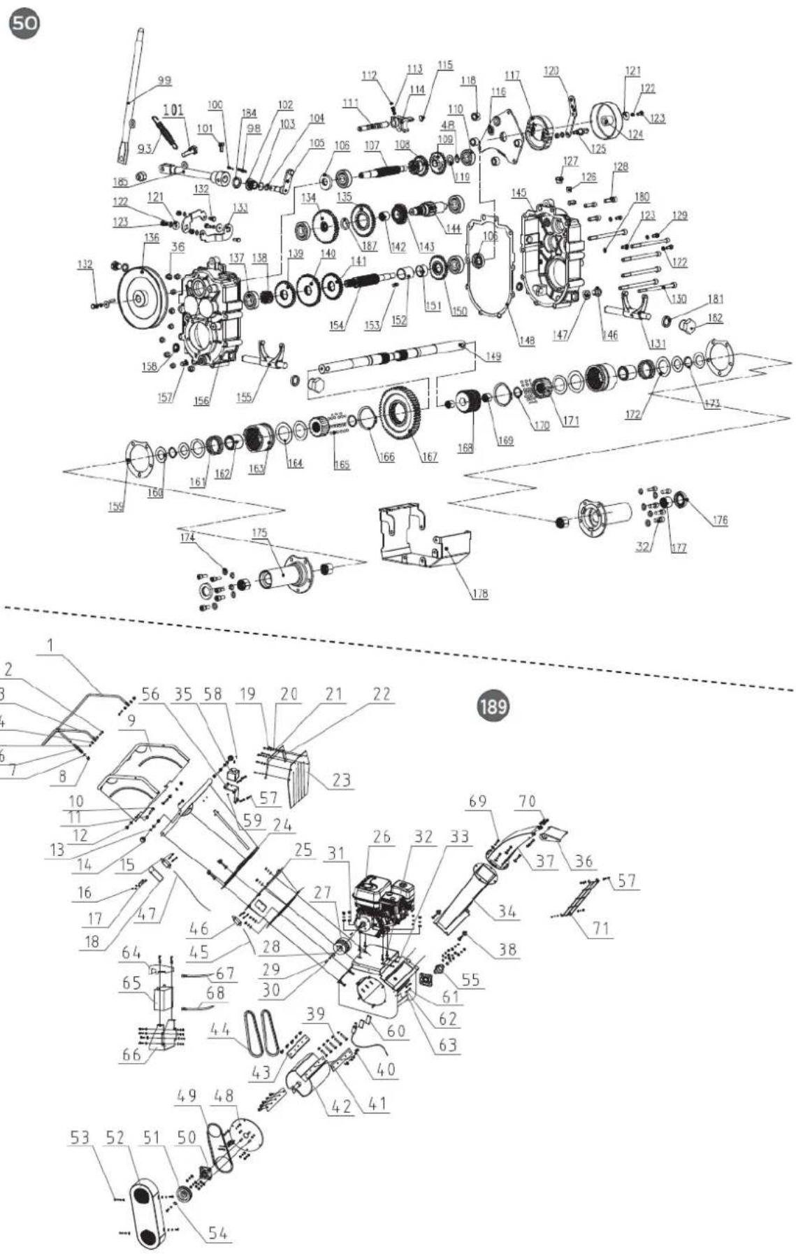
9. EXPLODED VIEW
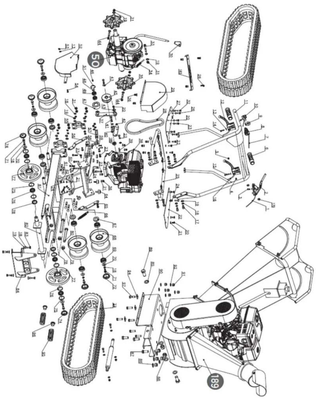
EN

DISTRIBUTION COMPANY
MILLASUR, SLU
CE DECLARATION OF CONFORMITY
In compliance with the various EC directives, this document confirms that, due to its design and construction, and as indicated by the CE marking affixed by the manufacturer, the machine identified herein meets the relevant and fundamental health and safety requirements of the aforementioned EC directives. This declaration authorizes the product to display the CE marking.
In the event that the machine is modified and this modification is not approved by the manufacturer and communicated to the distributor, this declaration will lose its value and validity.
Machine name: WOOD SHREDDER
Model: BIO120TR
[36087]
Recognized and approved standard to which it conforms:
Directive 2006/42/EC
2000/14/EC
2005/88/EC
Tested according to regulations:
EN ISO 12100:2010
INISO 3744:1995
EN ISO 11094:1991
Company seal
MILLASUR, S.L.U. Rúa Eduardo Pondal, 23 - Pol.Emp..Sigüelro 15688-Oroso-A Coruña Tel. (+34) 981 69 64 65 - Fax (+34) 981 69 08 61 e-mail: millasur@millasur.com CIF: B-15 749 922
15/12/2025
Holzhäcksler
BIO120TR
anova®
natural_image
Exterior view of a modern agricultural machine with visible engine and tracked wheels (no text or symbols)DE
ANOVA®
natural_image
Technical line drawing of a tracked robotic vehicle on a platform (no text or symbols)A. Scharnierbolzen
(1A). Knopf
(2A). Scharnierbolzen
4.1.4. Deflektor
A. Not-Aus-Schalter
B. Not-Aus-Kabel
C. Not-Aus-Hebel
natural_image
Diagram of a mechanical device with rotating blades and connecting rods, showing directional arrows (no text or symbols)A. Not-Aus-Griff
4.3.4. Zeitlupe
A. Einstellmutter
B. Kontermutter
C. Kontermutter.
natural_image
Technical illustration of a tracked robotic vehicle with mechanical components and bolts (no text or symbols)natural_image
Technical diagram of a mechanical assembly with labeled components and directional arrows indicating movement or flow (no text or symbols present)A. Innenlager

natural_image
Technical line drawing of a mechanical device with no visible text or symbols
natural_image
Technical line drawing of a mechanical device with rollers and components (no text or symbols)⚠ Warning
A. Verschleißplatte
natural_image
Technical line drawing of a mechanical device with a magnified inset showing a bolt and nut (no text or symbols)natural_image
Technical illustration of a mechanical assembly with a magnified inset showing a hand pulling a belt drive (no text or symbols present)natural_image
Mechanical assembly diagram showing a motor with pulleys and rotating components (no text or labels)DE

10. CE-ZERTIFIKAT
natural_image
Exterior view of a modern agricultural machine with visible engine and tracked wheels (no text or symbols)NL
ANOVA®
natural_image
Top-down diagram of a speaker emitting sound waves, with no text or symbols present.1.2.4. Materiaaltoevoer
Doe alleen schoon materiaal in de machine.
PLAATS UW HANDEN NIET ONDER DEZE LIJN
2. PRODUCTBESCHRIJVING
natural_image
Technical line drawing of a tracked robotic vehicle on a platform (no text or symbols)A. Scharnierpen
(1A). Knop
(2A). Scharnierpen
4.1.4. Afbuiger
A. Noodschakelaar

B. Noodstopkabel
C. Noodstophendel
natural_image
Diagram of a mechanical assembly with rotating parts and directional arrows indicating motion (no text or symbols)
HANDEN NIET TOEGESTAAN ONDER DEZE LIJN
A. Noodstophendel
A. Stelmoer B. Borgmoer
5.1.3. Stuurafstelling
natural_image
Technical illustration of a tracked robotic vehicle with visible components and assembly, no text or symbols presentnatural_image
Technical diagram of a robotic vehicle showing track and chassis components with directional arrows indicating motion (no text or labels)A. Buitenlager
B. Kunststof oliedop
C. Gat vullen
A. Binnenlager
natural_image
Technical line drawing of a mechanical device with gears and components (no text or symbols)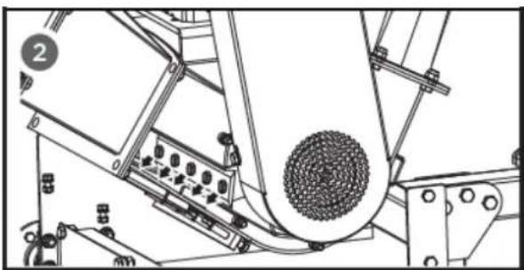
natural_image
Technical line drawing of a mechanical assembly with no visible text or symbols⚠ Waarschuwing
A. Slijtplaat
natural_image
Technical line drawing of a mechanical device with a magnified inset showing a bolt and nut (no text or symbols)natural_image
Technical illustration of a mechanical assembly with a magnified inset showing a hand pulling a belt drive system (no text or symbols present)5.2.9. V-riemspanning
natural_image
Mechanical assembly diagram showing a motor with rotating components and directional arrows (no text or labels)6. PROBLEEMOPLOSSING
6.1. Probleemoplossing
NL

DISTRIBUTIEBEDRIJF
MILLASUR, SLU