SL200H - Welding machine Anova - Free user manual and instructions
Find the device manual for free SL200H Anova in PDF.

User questions about SL200H Anova
0 question about this device. Answer the ones you know or ask your own.
Ask a new question about this device
Download the instructions for your Welding machine in PDF format for free! Find your manual SL200H - Anova and take your electronic device back in hand. On this page are published all the documents necessary for the use of your device. SL200H by Anova.
USER MANUAL SL200H Anova
natural_image
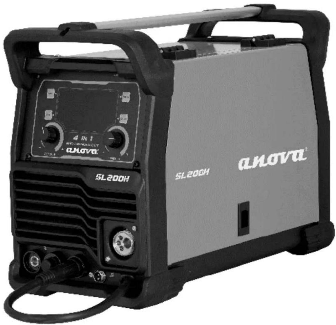
Exterior view of a black and white industrial testing device labeled 'SL200H' with no visible text or symbols on its body.ES
Millasur S.L.U.
Rúa Eduardo Pondal, nº 23 - Pol. Ind. Sigüeiro
15688 - Oroso, A Coruña - 981 696 465 - www.millasur.com
ANOVA®
10. CERTIFICADO CE
natural_image
Exterior view of a black and white industrial testing device labeled 'SL200H' with no visible text or symbols on its body.PT
anova®
Componentes da pistola de soldadura e do guia de arame
10. CERTIFICADO CE
natural_image
Exterior view of a black and white industrial testing device labeled 'SL200H' with no visible text or symbols on its body.FR
anova®
10. CERTIFICAT CE
SOCIÉTÉ DE DISTRIBUTION
MILLASUR, SL
DÉCLARATION DE CONFORMITÉ CE
natural_image
Exterior view of a black and white industrial testing device labeled 'SL200H' with control knobs and a beige cover (no readable text beyond branding)IT
anova®
flowchart
graph LR
    A["Top Component"] --> B["Bottom Component"]
    B --> C["Bottom Component with Arrow indicating downward motion"]
    C --> D["Bottom Component with Arrow indicating upward motion"]
10. CERTIFICATO CE
Instructions and user manual
natural_image
Exterior view of a black and white industrial testing device labeled 'SL200H' with no visible text or symbols on its body.EN
Millasur SLU
Rúa Eduardo Pondal, nº 23 - Pol. Ind. Sigüeiro
15688 – Oroso, A Coruña - 981 696 465 - www.millasur.com


ANOVA®
Anova We would like to congratulate you on choosing one of our products and guarantee the assistance and cooperation that has always distinguished our brand over time.
This machine is designed to last for many years and to be of great use if used according to the instructions in the user manual. We therefore recommend that you carefully read this instruction manual and follow all our recommendations.
For more information or questions, you can contact us through our web support at www.anova.es
INFORMATION ABOUT THIS MANUAL
Pay attention to the information provided in this manual and on the appliance for your safety and the safety of others.
- This manual contains instructions for use and maintenance.
- Take this manual with you when you go to work with the machine.
- The content is correct at the time of printing.
- We reserve the right to make changes at any time without affecting our legal responsibilities.
- This manual is considered an integral part of the product and must remain with it in case of loan or resale.
- Request a new manual from your distributor if it is lost or damaged.
READ THIS MANUAL CAREFULLY BEFORE USING THE MACHINE

To ensure your machine delivers the best results, carefully read the usage and safety guidelines before using it.
OTHER WARNINGS:
Improper use could cause damage to the machine or other objects.
Adapting the machine to new technical requirements could cause differences between the content of this manual and the product purchased.
Read and follow all instructions in this manual. Failure to follow these instructions could result in serious personal injury.
INDEX
- SAFETY INSTRUCTIONS
- TECHNICAL SPECIFICATIONS
- PRODUCT DESCRIPTION
- INSTALLATION AND START-UP
- MAINTENANCE AND STORAGE
- TROUBLESHOOTING
- WARRANTY
- ENVIRONMENT
- EXPLODED VIEW
10.CE CERTIFICATE
1. SAFETY INSTRUCTIONS
1.1. Safety warnings
When using this machine, observe the following safety instructions to exclude the risk of personal injury or property damage.
Also observe the special safety instructions in the relevant chapters. Where applicable, follow any legal directives or regulations for the prevention of accidents related to the use of the machine.
▲ Important
The machine must always be used according to the manufacturer's instructions in the instruction manual. The manufacturer and/or distributor will not be liable for damages resulting from improper use or modifications to the product. Do not use appliances with incorrect or missing parts. The distributor will provide you with information about replacement parts.
Note
Because Anova regularly improves its products, you may find slight differences between your machine and the descriptions in this manual. Anova may make changes to the machine without prior notice and without obligation to update the manual, although essential safety and operating features will remain unchanged.
Note: Due to technical product updates, this document is subject to change without notice.
The machine has an overheat protection system that prevents it from operating if it overheats. It is also protected against power surges and undervoltage. However, there are some risks associated with welding. Therefore, you must read and carefully follow the safety instructions below.
1.1.1. Use of protective accessories
The electric arc and the reflected radiation it emit damage unprotected eyes. Always protect your eyes and face with a suitable welding mask. The electric arc and welding spatter burn unprotected skin. Always wear protective gloves and clothing when welding.
1.1.2. Safe use of the welding machine
Some parts of the machine, such as the filler wire end and the soldering gun, become hot during use. The wire is also sharp and moves quickly, so be careful when threading it.
Never carry the machine on your shoulder during welding, but place it on a flat, secure surface.
Do not place the machine near or on hot objects, as the plastic cover could melt.
Do not move the protective gas cylinder when the control valve is in place. Securely mount the gas cylinder upright on a wall bracket or freestanding cylinder cart. Always close the gas cylinder after use.
1.1.3. Fire safety
Welding is always considered hot work, so you must pay attention to fire safety regulations. Protect the surrounding area from welding spatter. Remove flammable materials from the immediate vicinity of the welding area and ensure that the site has adequate firefighting equipment.
When welding container-type parts, be aware of the hazards specific to special work areas, such as the risk of fire and explosion. A fire caused by sparks can occur even after several hours. Do not weld in flammable or explosive areas; it can cause very serious injuries.
1.1.4. Supply voltage
- Do not insert the welding machine inside the workpiece, for example, in a container or in a car.
- Do not place the welding machine on a wet surface.
- Replace faulty cables immediately, as they are life-threatening and can cause a fire.
- Make sure the cables are not pinched or in contact with sharp edges, among other things.
1.1.5. Welding circuit
- Isolate yourself from the welding circuit using dry, clean protective clothing.
- Do not work on a wet surface.
- Do not use damaged welding cables.
- Do not place the welding gun or ground clamp on the welding machine or any other electrical device.
1.1.6. Welding fumes
- Ensure adequate ventilation. Take special precautions when welding metals containing lead, cadmium, zinc, mercury, or beryllium.
- Sufficient clean air supply can also be improved by using a fresh air mask.
1.2. Intended use
The equipment must be used only for its prescribed purpose. Any other use will be considered misuse. The operator will be liable for any damage or injury of any kind caused as a result.
Note: The operating instructions provided by the manufacturer should be retained and consulted to ensure that the equipment is used and maintained correctly.
In synergic mode, the welding voltage and wire feed speed are adjusted via rotary controls according to the thickness of the sheet metal being welded. This makes selecting the appropriate parameters simple.
1.2.1. About welding
In addition to the welding machine, the weld outcome is influenced by the workpiece and the welding environment. Therefore, the recommendations in this manual should be followed.
During welding, the electric current is conducted through the welding gun nozzle to the wire and, via the wire, to the workpiece. The grounding cable, connected to the workpiece, conducts the current back to the machine, forming the necessary closed circuit. Unrestricted current flow is possible when the grounding clamp is properly attached to the workpiece and the clamp's attachment point is clean, free of paint and rust.
During welding, shielding gas is necessary to prevent air from mixing with the weld pool. Carbon dioxide or a mixture of carbon dioxide and argon are suitable shielding gases. Some filler wires generate their own shielding gas as they melt, thus eliminating the need for an additional shielding gas.
2. TECHNICAL SPECIFICATIONS
| Characteristics | SL200D |
| Supply voltage | AC 230V ± 15% ~ 50Hz |
| Current range (A) | MIG20-200TIG20-190MMA20-190CUT 20-40 |
| No-load voltage (V) | TIG/MMA/MIG-80CUT-380 |
| Wire diameter | 0.8-1.0mm |
| Electrodes | 1.6-5mm |
| Efficiency | 85% |
| Insulation class | F |
| Wire coil | 1-5kg |
Note: Due to continuous improvements in R&D, this document and its technical characteristics may be modified without prior notice.
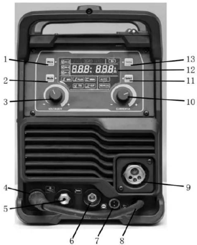
3. PRODUCT DESCRIPTION

- Wire diameter selector :0.8/0.9/1.0 mm
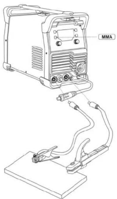
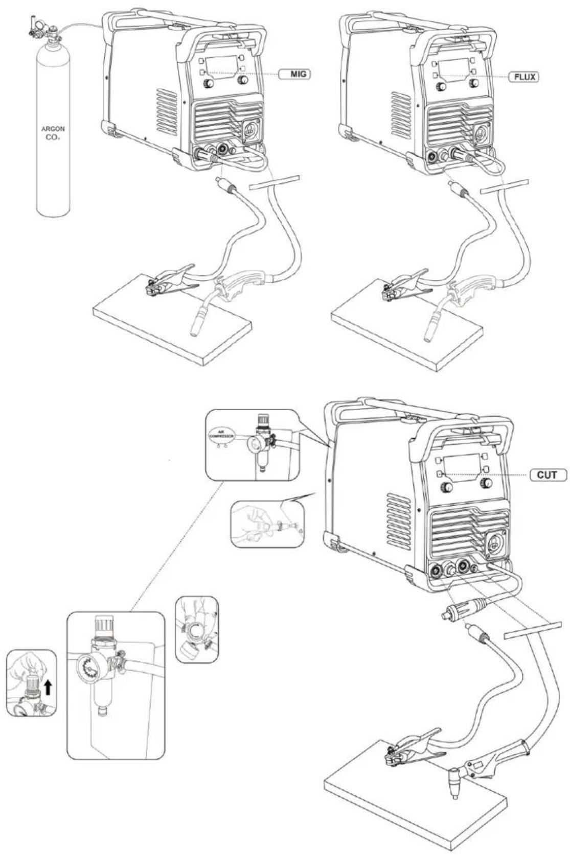
- Welding type: GAS MIG/Flux MIG/TIG/MMA/CUT
- Voltage (manual MIG)
- Ground clamp connector
- Cutting torch connector
- MMA / FLUX MIG welding clamp connector
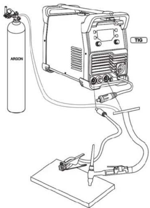
- 2-pin connector (For plasma cutting Cut / TIG torch)
- Welding connector cable
- MIG torch connector
- Intensity selector
- Selector: Manual/Automatic
- LCD display
- Quick cable power supply
4. INSTALLATION AND START-UP
- Turn off the power switch before any electrical connection operation.
- Avoid using it in the rain.
Note: Install the machine strictly according to the following steps. If you have any questions, please contact your authorized dealer.
4.1. Before startup
The products are packaged in specially designed boxes. However, before using them, always make sure they haven't been damaged during shipping. Also, check that you have received the products you ordered and the necessary instruction manuals.
Transport
- The machine must be transported in a vertical position.
- Always move the welding machine by lifting it by the handle.
- Never disconnect it from the welding gun or other cables.
Atmosphere
- The machine is suitable for indoor and outdoor use. However, it should be protected from heavy rain and direct sunlight.
- Store it in a dry, clean place, and protect it from sand and dust during use and storage.
- The recommended operating temperature range is -20^ to +40^ .
- Position the machine so that it does not come into contact with hot surfaces, sparks, or splashes.
- Make sure the airflow in the machine is not restricted.
4.1.1. Application connection with and without gas
Gas application (with solid cable)
The welding cable connector connects to “+”, the ground clamp connects to “-”, the torch connects to “ and hold it.
Without gas application (using tubular wire)
The welding cable connector connects to “-”, the ground clamp connects to “+”, the torch connects to “ and hold it.
EN
EN
4.1.2. Connections
Connection to the electrical grid
The machine is equipped with a power cord. Connect the power cord to the mains.
If you use an extension cable, its cross-sectional area must be at least equal to that of the power cable (3 x 4 mm ^2 ). The maximum length of the extension cable is 50 m.
The machine can also be used with a generator. The recommended power output should be higher than the machine's maximum capacity.
Grounding
Connect the ground cable to the machine. Clean the workpiece surface and secure the ground cable clamp to the workpiece to create a closed, interference-free circuit, which is necessary for welding.
Welding gun
Once the welding gun is connected to the machine, it conducts the filler wire, shielding gas, and electric current to the weld. Pressing the trigger starts the flow of shielding gas and the wire feed. The arc ignites when the filler wire touches the workpiece.
The neck of the tube can rotate 360^ . When rotating it, always make sure it is turned almost to the stop. This prevents damage and overheating.
If you are using filler wire of a diameter other than 0.8 mm, change the contact tip of the soldering gun to match the wire thickness.
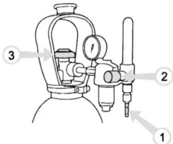
Connecting the gas hose to a typical control valve
-
Connect the hose to the gas bottle's control valve and tighten the connector.
-
Adjust the flow rate using the screw on the control valve. A suitable flow rate of shielding gas is 8-15 l/min.
-
Close the bottle valve after use.
Shielding gas
The shielding gas used for steel wires is carbon dioxide or a mixture of argon and carbon dioxide, which replaces the air in the arc zone. The thickness of the sheet metal being welded and the welding power determine the flow rate of the shielding gas.
Connect the mouth connector of the protective gas hose to the machine's hose connector and the end of the hose connector to the gas bottle's control valve.
Note: Use a shielding gas suitable for welding the material. Securely fix the gas cylinder in an upright position before installing the control valve.
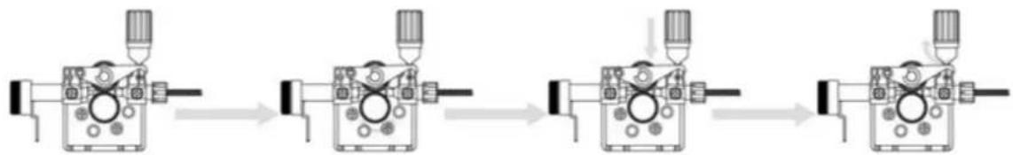
4.2. Changing the feed roller groove
The feed roller groove is factory-set for welding filler wires 0.8 to 1.0 mm in diameter. If 0.6 mm thick filler wire is used, the feed roller groove must be modified.
flowchart
graph LR
    A["Start"] --> B["Drive"]
    B --> C["Adjustment"]
    C --> D["Close-up"]
    D --> E["End"]
Changing the feed roller groove
- Open the feed roller from the pressure control lever.
- Turn on the machine using the main switch.
- Press the trigger of the welding gun and move the feed roller to a position where its locking screw is facing upwards and can be opened.
- Turn off the power at the main switch.
- Open the feed roller locking screw with a 2.0 mm Allen key approximately half a turn.
- Remove the feed roller from its shaft.
- Turn the feed roller over and reinstall it on its shaft all the way in, making sure the screw is level with the shaft.
- Tighten the feed roller locking screw.
4.3. Threading the filler wire
- Open the reel housing by pressing the release button and install the wire reel so that it rotates counterclockwise. You can use a 1 kg or 5 kg wire reel in the machine.
- Secure the reel with a reel lock.
- Unhook the end of the cable from the reel but hold it the whole time.
- Straighten the end of the wire for about 20 cm and cut the wire at the straightened point.
- Open the pressure control lever, which will open the feed gear.
- Pass the cable through the rear cable guide to the gun's cable guide.
- Close the feed gear and secure it with the pressure control lever. Make sure the wire passes through the feed roller slot.
- Adjust the compression pressure using the pressure control lever to the halfway point. If the pressure is too high, metal fragments will break off from the wire surface and may damage it. Conversely, if the pressure is too low, the feed gear will slip, and the wire will not advance properly.
- Press the trigger of the welding gun and wait for the wire to come out.
- Close the reel housing cover.
Caution
When inserting the wire into the gun, do not point it at yourself or others, and do not place your hand in front of the tip, as the cut end of the wire is extremely sharp. Also, do not place your fingers near the feed rollers, as they could become trapped.
4.4. Controls and indicator lights
- The welding power is adjusted according to the thickness of the sheet to be welded.
- The indicator lights show the machine's standby mode and warn of possible overheating.
- When you turn on the machine, a green power light comes on.
- Simultaneously, the standby switch indicator light comes on.
☐ If the machine overheats or the supply voltage is too low or too high, the welding operation stops automatically and the yellow overheat indicator lights up.
☐ The light turns off when the machine is ready to resume operation. Ensure there is sufficient space around the machine for free air circulation and cooling.
4.5. Welding power adjustment
Adjusting the welding power according to the sheet thickness simultaneously affects both the wire feed speed and the current intensity. This is a good starting point for welding in various working situations. However, the type of connection and the root opening can also influence the required welding power.
Select the correct welding power control parameter based on the thickness of the sheet metal being welded. If the sheets have different thicknesses, use their average as the default value.
The sheet thickness scale is indicated in millimeters and is based on a wire diameter of 0.8 mm. When using 0.6 mm wire, adjust the welding power control slightly above the sheet thickness used, and consequently, slightly below with wires from 0.9 to 1.0 mm.
5. MAINTENANCE AND STORAGE
5.1. Maintenance
Proper maintenance is essential for safe and efficient operation. It will also help extend the machine's lifespan and keep it in optimal working condition.
Always select accessories recommended and approved by the manufacturer. Using other unapproved accessories and replacement parts may damage the machine.
Perform a weekly check of your machine to ensure everything is working properly.
Caution
Operators must hold valid qualification certificates demonstrating their complete electrical and safety skills and knowledge. Ensure the machine's power cord is disconnected from the mains before operating the welding machine.
- Periodically check that the internal circuit connections are in good condition (especially the plugs). Tighten any loose connections. If there is corrosion, remove it with sandpaper and then reconnect.
- Keep hands, hair, and tools away from moving parts, such as the fan, to avoid personal injury or damage to the machine.
-
Clean the dust periodically with clean, dry compressed air. If welding in a contaminated environment, the machine should be cleaned daily. The compressed air pressure must be at a suitable level to prevent damage to small internal parts of the machine.
-
Prevent rain, water, and steam from entering the machine. If any leaks occur, dry them and check the insulation of all equipment components. The machine may only be used once all abnormal phenomena have ceased.
- Periodically check that the insulation on all cables is in good condition. If there is any damage, replace it.
- Place the machine in its original packaging in a dry place if you are not going to use it for an extended period.
When performing machine maintenance, its level of use and environmental conditions must be taken into account. Proper use and regular maintenance will prevent unnecessary breakdowns.
Caution
Disconnect the machine from the mains power supply before handling the electrical cables.
5.1.1. Daily maintenance
- Remove any solder spatter from the soldering gun tip and inspect the condition of the parts. Replace any damaged parts immediately.
- Check that the insulating tips on the neck of the soldering gun are intact and in place. Immediately replace any damaged insulating parts with new ones.
- Check that the connections of the welding gun and the ground cable are tight.
- Check the condition of the power supply voltage and the welding cable and replace any faulty cables.
5.1.2. Wire feeding mechanism maintenance
- Check the wire feed mechanism at least every time you change the spool.
- Check the wear on the feed roller groove and replace it when necessary.
- Clean the welding gun wire guide with compressed air.
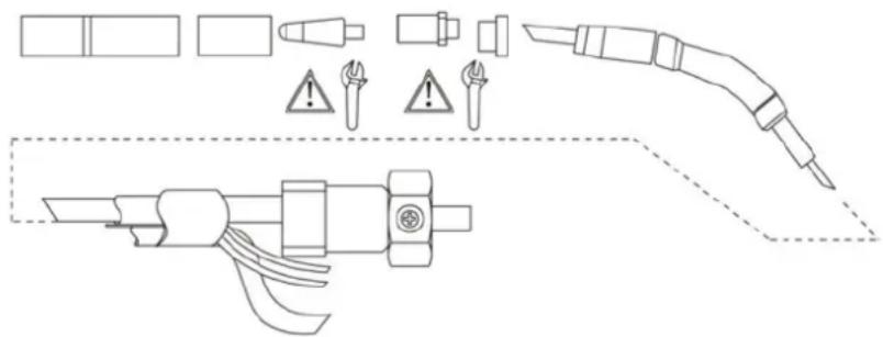
Parts of the welding gun and wire guide
5.2. Cleaning the cable guide
The pressure from the feed rollers removes metallic dust from the surface of the filler wire, which is then deposited on the wire guide. If the wire guide is not clean, it will gradually become clogged and cause wire feeding failures. Clean the wire guide as follows:
- Remove the gas nozzle, contact tip, and contact tip adapter from the soldering gun.
- Using an air gun, blow compressed air through the wire guide.
-
Clean the wire feed mechanism and reel housing with compressed air.
-
Reassemble the soldering gun parts, tighten the contact tip and contact tip adapter with a wrench.
5.3. Change the cable guide
If the cable guide is too worn or completely obstructed, replace it with a new one following these instructions:
- Disconnect the welding gun from the machine.
a. Disconnect the power cord clamp from the gun by opening the screws.
b. Disconnect the gun's power cord from the machine's pole.
c. Disconnect the connector from the machine's trigger conductors.
d. Open the weapon mounting nut.
e. Carefully remove the gun from the machine, so that all parts come out through the cable hole at the front.
- Open the wire guide mounting nut, exposing the end of the wire guide.
- Straighten the welding gun cable and remove the wire guide from the gun.
- Insert a new wire guide into the gun. Make sure the wire guide is fully inserted into the contact tip adapter and that there is an O-ring on the end of the guide that connects to the machine.
- Tighten the wire guide in place with the mounting nut.
- Cut the wire guide 2 mm from the mounting nut and file the sharp edges of the cut to round them.
- Replace the gun in place and tighten the parts with a wrench.
6. TROUBLESHOOTING
Note: We are constantly improving this product, therefore, some parts of this welder may be changed to achieve better quality, but the main functions and operations will not be altered or changed.
| Issues | Possible cause |
| The cable doesn't move or the cable feeder gets tangled. | The feed rollers, cable duct, or contact points are defective.- Check that the feed rollers are neither too tight nor too loose.- Check that the feed roller groove is not too worn.- Check that the cable conduit is not obstructed.- Check that there is no splashing at the tip of the conduit and that the orifice is not obstructed or worn. |
| The main switch indicator light does not turn on. | The machine has no power supply.- Check power supply voltage fuses- Check the power cord and plug. |
| The result of the welding is not good. | The result of welding is influenced by several factors.- Check the welding voltage setting and wire speed.- Check that the ground clamp is properly attached. The attachment point must be clean and both the cable and its connections must be intact.- Check the flow of shielding gas from the tip of the welding gun.- The supply voltage is irregular, too low or too high. |
| The overheating indicator lights up. | The machine is overheating.- Check that the cooling air can flow without obstruction.- The machine's volume/capacity ratio has been exceeded; please wait for the indicator light to turn off.- The supply voltage is too low or too high |
7. WARRANTY
If your product suffers any manufacturing defect during the established warranty period, please contact or go directly to your point of sale with the necessary documentation.
Your purchase receipt should be kept as proof of the purchase date. Your tool must be returned to your distributor in acceptable and clean condition, in its original molded case, if applicable, along with your corresponding proof of purchase.
7.1. Warranty period
The legal warranty period for the product begins on the original date of purchase by the first initial buyer and its duration will be that established by the Royal Decree-Law on the protection of consumers and users against situations of social and economic vulnerability of the year corresponding to the time of acquisition of the product.
Some countries do not have limitations on how long an implied warranty lasts or do not allow the exclusion or limitation of consequential or incidental damages, in which case the above limitation and exclusion may not apply to you. This warranty gives you specific legal rights, and you may also have other rights that vary from state to state or country to country.
7.2. Exclusions
This warranty does not cover product damage or performance problems caused by:
- Natural wear and tear from use.
- Misuse, negligence, careless operation, or lack of maintenance.
- Defects caused by improper use, damage caused by handling by personnel not authorized by Anova or use of non-original spare parts.
EN
- Defects in normal wear parts, such as bearings, brushes, cables, plugs or accessories such as drills, drill bits, saw blades, etc.
- Damage or defects resulting from abuse, accidents, or alterations.
- Incorrect use and storage (explicit reference to the fact that the rules described in the operating instructions have not been followed).
- Wear and tear caused by the customer (e.g., broken saw blades, consumed carbon brushes, etc.).
- Wear and secondary damage due to lack of maintenance, repair, lubricants (e.g., overheating damage due to blocked cooling slots, bearing damage as a result of dirt, frost damage, etc.)
- Damage as an obvious result of overuse/overload.
- Damage caused by inappropriate supplies (e.g., incorrect fuel)
- Load-induced breakage of housing components or accessories due to abnormal stress
- Load-induced deformation of the housing components or accessories due to abnormal stress.
- Damage resulting from the operation of supplies that are overfilled or leak due to improper storage, improper cleaning agents, or other damaging chemical components.
- Damage due to improper exposure to extreme temperatures (e.g., frost cracking, thermal deformation of components, etc.)
- Damage from permanent exposure to ultraviolet radiation.
- Damage caused by inadequate maintenance.
- Any damage caused by failure to follow the instructions in the instruction manual
- Any product that has been repaired by an unqualified professional.
- Any product connected to an unsuitable power source (amps, voltage, frequency).
- Any damage caused by external influences (water, chemicals, physical, impacts) or foreign substances.
- Use of unsuitable accessories or parts.
- It does not cover defects in normal wear and tear parts, nor does it cover damage or defects resulting from abuse, accidents or alterations, nor transportation costs.
Furthermore, the warranty is voided if the product has been altered or modified, or if the trademark/serial number of the machine has been defaced or removed.
Routine maintenance, tuning, adjustments, or normal wear and tear are not covered under this warranty.
This manual does not cover all possible situations regarding warranty exclusions; for more information, please contact your nearest Anova distributor.
7.3. In case of incident
The warranty must be correctly completed with all the requested information, and accompanied by the purchase invoice.
Anova reserves the right to refuse any claim where the purchase cannot be verified or where it is clear that the product was not properly maintained (maintenance, clean ventilation slots, lubrication, regularly maintained carbon brushes, cleaning, storage, etc.).
Private use is defined as personal domestic use by an end consumer. Commercial use, on the other hand, means all other uses, including uses for business purposes, income generation, or rental. Once the product has been used for commercial purposes, it will be considered a commercial product thereafter for the purposes of this warranty.
These are our standard warranty terms, but occasionally there may be additional warranty coverage not specified at the time of publication. For more information, please contact your nearest authorized Anova dealer or visit www.millasur.com.
Warranty service is only available through authorized Anova distributors. You can find your nearest distributor on our distributor map at www.anova.es.
8. ENVIRONMENT


It is essential to ensure that products and their components are disposed of responsibly to protect the environment. Below, you will find general guidelines for the proper disposal of various materials used in your machine.
Dispose of your machine in an environmentally friendly way. We shouldn't throw machines away with the regular household waste. Their plastic and metal components can be sorted according to their type and recycled.
When disposing of machinery or metal products, it's important to remember that their metal components, such as iron, steel, or aluminum, must be properly recycled at metal recycling facilities. This will contribute to their potential reuse in the manufacture of new products.
Oils and Fuels
Used oils and fuels, among other things, must be recycled properly. Do not pour these liquids down drains, into soil, rivers, lakes, or seas, as they can cause serious environmental damage. Take them to a recycling center or specialized collection point. This process helps prevent water and soil contamination and allows for the safe reuse of oils, if possible.
Plastics
Plastics should be separated and taken to designated recycling points. Do not throw them away with regular household waste. Plastics can be recycled, helping to reduce waste.
Cardboard
Packaging materials, such as cardboard, are recyclable. Be sure to separate clean, dry cardboard and place it in designated recycling containers or at an official waste collection point. Do not dispose of it with household waste.
Batteries
Batteries and other electronic components from machines must be disposed of at designated collection points to prevent the release of toxic substances into the environment. Do not throw them away with regular trash. Take them to appropriate recycling centers for safe and responsible handling.
By following these guidelines, you contribute to environmental protection and resource conservation. For more information on material disposal and recycling, please contact your local authorities and consult the necessary information.
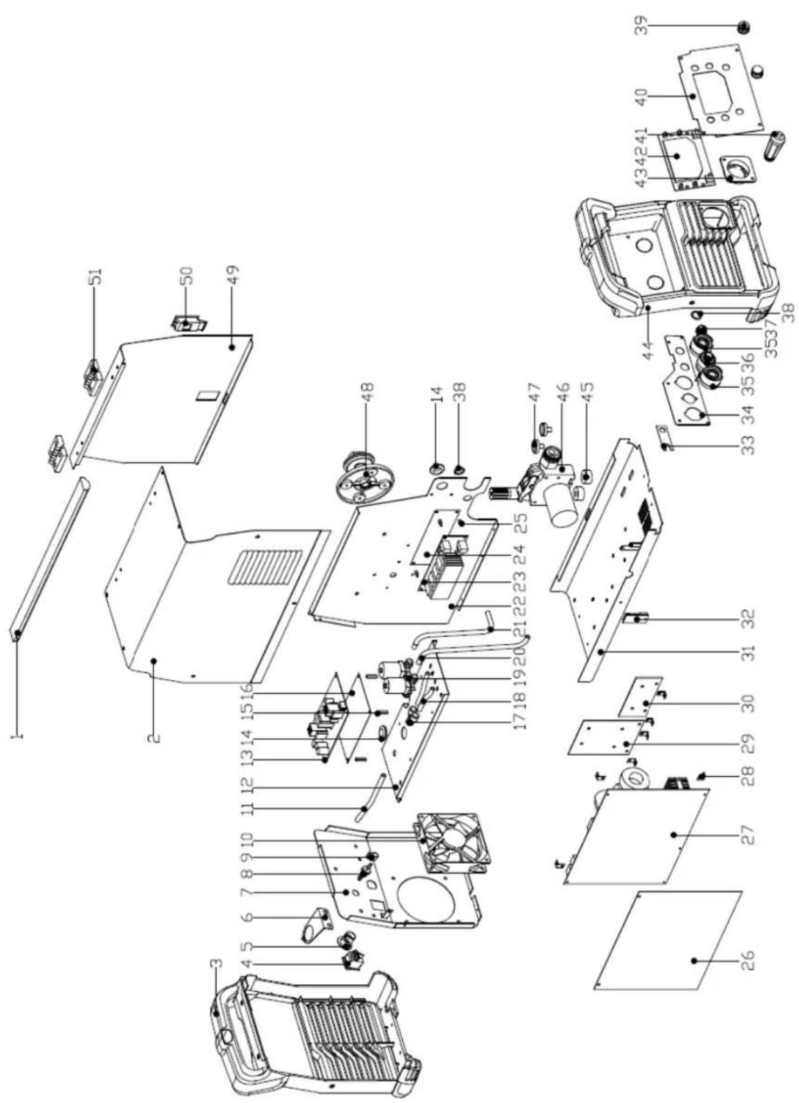
9. EXPLODED VIEW
10. CE CERTIFICATE
DISTRIBUTION COMPANY
MILLASUR, SL
CE DECLARATION OF CONFORMITY
In compliance with the various EC directives, this document confirms that, due to its design and construction, and as indicated by the CE marking affixed by the manufacturer, the machine identified herein meets the relevant and fundamental health and safety requirements of the aforementioned EC directives. This declaration authorizes the product to display the CE marking.
In the event that the machine is modified and this modification is not approved by the manufacturer and communicated to the distributor, this declaration will lose its value and validity.
Machine name: WELDER
Model:SL200H
[MIG200L]
Recognized and approved standard to which it conforms:
Directive 2014/35/EU
2014/30/EU
Tested according to regulations:
EN 60974-10:2021
EN 61000-3-11:2019
EN IEC 60974-1:2022+A11:2022
EN 61000-3-12:2019+A1:2021
Company seal
MILLASUR, S.L.U.
Rúa Eduardo Pondal,23 · Pol.Emp..Sigüeiro
15688-Oroso-A Coruña
Tel.(+34) 981 69 64 65 - Fax (+34) 981 69 08 61
e-mail: millasur@millasur.com
CIF: B-15 749 922
07/10/2025
Schweißmaschine
SL200H
ANOVA®
natural_image
Exterior view of a black and white industrial testing device labeled 'SL200H' with control knobs and a beige casing (no readable text beyond branding)DE
Millasur SLU
Rúa Eduardo Pondal, Nr. 23 – Pol. Ind. Sigüeiro
15688 – Oroso, A Coruña – 981 696 465 – www.millasur.com
ANOVA®
10. CE-ZERTIFIKAT
natural_image
Exterior view of a black and white industrial testing device labeled 'SL200H' with no visible text or symbols on its body.NL
ANOVA®
ANDERE WAARSCHUWINGEN:
3. PRODUCTBESCHRIJVING
6. PROBLEEMOPLOSSING
10. CE-CERTIFICAAT
DISTRIBUTIEBEDRIJF
MILLASUR, SL