Bolero Flux TT 604400 Inox A++ - Basket CECOTEC - Free user manual and instructions
Find the device manual for free Bolero Flux TT 604400 Inox A++ CECOTEC in PDF.

User questions about Bolero Flux TT 604400 Inox A++ CECOTEC
0 question about this device. Answer the ones you know or ask your own.
Ask a new question about this device
Download the instructions for your Basket in PDF format for free! Find your manual Bolero Flux TT 604400 Inox A++ - CECOTEC and take your electronic device back in hand. On this page are published all the documents necessary for the use of your device. Bolero Flux TT 604400 Inox A++ by CECOTEC.
USER MANUAL Bolero Flux TT 604400 Inox A++ CECOTEC
natural_image
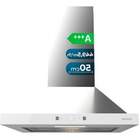
Exterior view of a white stainless steel kitchen air duct with ventilation grilles and ventilation grilles, shown against a solid blue background (no text or symbols visible)Safety instructions 9
-
Parts and components 71
-
Before use 71
-
Installation 71
-
Operation 75
-
Troubleshooting 77
-
Cleaning and maintenance 78
-
Recycling of electrical and electronic
equipment 78
-
Copyright 79
-
Simplified EU Declaration of Conformity 79
SOMMAIRE
EN · The coding in this manual is generic and applies to all code variants of the appliance.
Read the following instructions carefully before using the appliance. Keep this instruction manual for future reference or new users.
- This appliance can be used by children aged 8 years and above and people with reduced physical, sensory or mental capabilities or lack of experience and knowledge if they have been given supervision or instruction concerning the use of the appliance in a safe way and understand the hazards involved. Children must not play with the appliance.
- Cleaning and user maintenance must not be carried out by children without supervision.
- This appliance is intended for domestic use only and is not suitable for use in commercial establishments such as bars, restaurants, farms, hotels, motels, and offices.
- Means for disconnection must be incorporated in the fixed wiring in accordance with the wiring rules.
- The air discharge regulations must be complied with.
- Things you should never do:
I. Do not attempt to use the kitchen hood without the mesh filter or if the filter is excessively dirty or greasy!
II. Do not install the kitchen hood above a cooker with a high-level grill.
III. Do not leave pans unattended during use because overheated fats or oils may catch fire.
- Accumulation of grease in the kitchen hood can cause a fire hazard. Clean the appliance according to the instructions in this manual.
- Exercise extreme caution when cleaning the appliance. Risk
ENGLISHENGLISH
of burns and/or cuts. We recommend the use of gloves.
- Never leave open flames under the kitchen hood.
- If the kitchen hood is damaged, do not attempt to use it.
- When the kitchen hood and other non-electrically powered
- appliances are in simultaneous operation, the negative pressure in the room must not exceed 4 Pa (4 x 10⁻⁵ bar).
- Important! Always disconnect the power supply during installation and maintenance.
- The kitchen hood must be installed in accordance with the installation instructions and in compliance with all measurements.
- All installation work must be carried out by a competent person or a qualified electrician.
- Dispose of the packaging material carefully. Children are vulnerable to it.
- Pay attention to sharp edges inside the
- kitchen hood, especially during installation and cleaning.
- Make sure that the duct does not have bends sharper than 90 degrees, as this will reduce the efficiency of the kitchen hood.
- Warning: Failure to install the screws or fastening device in accordance with these instructions may result in electrical hazards.
- Warning: Before accessing the electrical terminals, all power supply circuits must be disconnected.
- There must be adequate ventilation of the room when the kitchen hood is used at the same time as gas or other fuel burning appliances.
- Caution: The appliance and its accessible parts may become hot during operation. Be careful not to touch any accessible parts. Children under 8 years old must stay away, unless
they are supervised.
- Local air discharge regulations must be complied with.
- For safety reasons, only use the supplied fixing or mounting screws (if applicable, depending on the model) or screws of the same size as those recommended in this instruction manual.
- Do not use a steam cleaner.
- Never try to put out the fire with water. Instead, turn off the appliance and smother the flame with, e.g., a fireproof lid or blanket.
- Never use extension leads, multiple socket connections or external timer connection elements.
- If the power cable is damaged, it must be replaced by the official Cecotec Technical Support Service or by similarly qualified technicians to prevent hazards.
- The appliance must not be operated if the power supply cord is damaged or cut.
- If the appliance stops working or malfunctions abnormally, disconnect it from the mains and contact the official Cecotec Technical Support Service.
- Cecotec disclaims all liability for any damage or injury caused as a result of failure to follow the installation and/or operating instructions contained in this instruction manual.
- There must be adequate ventilation of the room when the kitchen hood is used at the same time as gas or other fuel burning appliances.
- There is a risk of fire if cleaning is not carried out according to the instructions.
- Do not flambé under the kitchen hood.
- CAUTION: Accessible parts can become hot when used with cooking appliances.
- Air must not be discharged into a duct that is used to exhaust
fumes from appliances burning gas or other fuels.
- The minimum distance between the worktop and the lowest part of the kitchen hood, when it is located above a gas appliance, must be at least 65 cm. If the installation instructions for the gas appliance specify a greater distance, this must be taken into account. The distance of 65 cm can be reduced for:
o Non-combustible parts of kitchen hoods. - Parts operating at safety extra-low voltage (provided that these parts do not give access to live parts if they are deformed).
- The air discharge regulations must be complied with.
- Cecotec disclaims all liability for any damage or injury caused as a result of failure to follow the installation and/or operating instructions contained in this instruction manual.
- The kitchen hood is intended for installation only over a hob with four cooking zones.
INSTRUCTIONS DE SÉCURITÉ
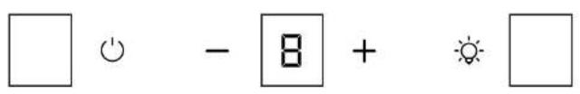
- Gesture control sensor
- Power on/off touch icon
- Extraction power decrease touch icon
-
Display
-
Extraction power increase touch icon
-
Light on/off touch icon
-
Gesture control sensor
Note:
The graphics in this manual are schematic representations and may not exactly match the product.
2. BEFORE USE
- This appliance comes in a packaging designed to protect it during transport. Remove the appliance from its box. You can keep the original box and other packaging materials in a safe place to prevent damage to the appliance if you need to transport it in the future. If you wish to dispose of the original packaging, make sure all items are recycled properly.
- Check that all parts and components are included and in good condition. If any of them are missing or damaged, please contact Cecotec's Official Technical Support Service immediately.
Box content:
- Extractor hood
- Carbon filter (not installed) x2
- Instruction manual
- Do not remove the product's serial number in order to keep proper traceability if technical assistance is required.
3. INSTALLATION
Figure 2 shows the dimensions (in mm) of the extractor hood required for installation.
ENGLISHENGLISH
Ventilation requirements
- The ventilation system outlet must lead outdoors, except for recirculation installations (without external outlet).
- Do not position the ventilation system outlet in any enclosed indoor space within the building (such as lofts, attics or false ceilings).
- Use only metal ducting. Rigid metal ducting is recommended. Plastic or flexible metal sheet ducting is not recommended.
- The ventilation system must have a damper. If the roof or wall cap already has a damper, do not use the damper supplied with the extractor hood.
- To maximise the ventilation system's performance:
o Minimise duct run length and number of transitions and elbows.
o Maintain consistent duct size.
- Seal all connections with duct tape to prevent leaks.
- Seal the wall or roof opening around the cap with sealant.
- The extractor hood must be installed at a height of 650–750 mm above the hob.
Ventilation methods
The following figures show different types of ventilation:
Roof ventilation
Fig. 3
-
Roof cap
-
Round vent
-
Hood
Wall ventilation
Fig. 4
-
Wall cap
-
Round vent
-
Hood
Recirculation (without external outlet)
Fig. 5
-
Deflector
-
Hood
Note:
Please follow these instructions to ensure optimal air extraction. Failure to follow these guidelines will reduce performance and increase the noise level of the extractor hood.
- All installation work must only be carried out by a qualified electrician or competent
person.
- Do not connect the hood's extraction duct to an existing ventilation system being used for another appliance, such as a chimney.
- The air extraction duct bend angle must not be less than 120°. Align the duct horizontally. Alternatively, the duct should rise from the starting point and lead to an external wall.
- After installation, ensure the extractor hood is level to prevent grease accumulation on one side.
- Ensure the selected extraction duct for installation complies with relevant standards and is fire-resistant.
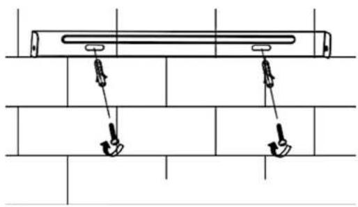
Extractor hood installation
Figure 6 shows the accessories included for installation.
- Drill 3 holes in the wall to install the mounting plate. Then install it (Figure 7).
Fig. 7 key:
- Hole
- Expansion plug
- Mounting plate
-
Screw (4 mm x 30 mm)
-
Hang the extractor hood on the mounting plate. Remove the filters and mark the positions for the other two safety screws on the wall from inside the hood (Figure 8).
Chimney installation
- Slide the upper chimney section into the lower section. Pay attention to the ventilation slot positions. Consider whether the system is for air extraction or recirculation (Figure 9).
Fig. 9 key:
- Air extraction.
- Upper part of the chimney (interior).
- Wall bracket.
- Lower part of the chimney (exterior).
-
Air recirculation.
-
Slide the upper chimney section into the lower section. Pay attention to the ventilation slot positions. Consider whether the system is extraction or recirculation.
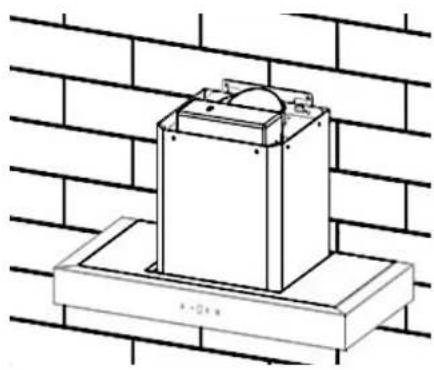
- Install the lower wall bracket to the lower chimney section following these instructions
ENGLISHENGLISH
(Figure 10):
- Place the chimney on the hood.
- Mark the points on the wall for the lower bracket holes, then drill the holes.
-
Secure the lower bracket to the wall using 2 wall plugs and 2 screws (4 mm x 30 mm).
-
Extend the upper chimney section to the desired height.
- Mark the points on the wall for the upper bracket holes, then drill the holes.
- Secure the upper bracket to the drilled positions using 2 wall plugs and 2 ST4 x 30 mm screws.
- Secure the upper chimney section to the wall bracket using 2 ST4 x 8 mm screws (Figure 11).
Fig. 11 key:
- Wall plug.
- Wall bracket
- Screw (4 mm x 8 mm).
-
Screw (4 mm x 30 mm).
-
The bend angle of the air outlet pipe must not be less than 120°. Position the duct horizontally. Alternatively, the duct can rise from the hood and be directed to an exterior wall.
- After installation, ensure that the extractor hood is level to prevent grease build-up on one side (Fig. 12).
Note: Make sure the chosen extraction duct complies with all regulations and is fire-resistant.
Air outlet pipe installation
Note: Remove the protective film before installation.
- Valve installation
- Install the non-return check valve on the hood's air outlet as shown in the figure.
- Attach the duct to the extractor hood's air outlet as shown in Figure 13.
Fig. 13 key:
- One-way anti-return valve
- Air outlet
- Air outlet pipe
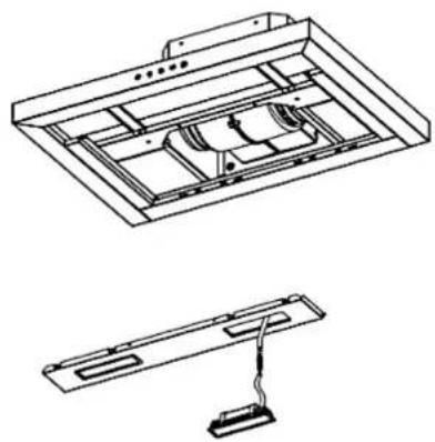
Replacing the LED light
Notes:
The LED light must only be replaced by qualified technicians or by Cecotec's Official.
Technical Support Service.
- Unplug the power cord before replacing it.
- Before replacing the light, make sure that it is not hot.
- Always use gloves or cloths to avoid direct contact with LED lights.
-
Remove the mesh filters.
-
Reach inside the hood to gently push the LED bulb outwards. Use your other hand to grip and pull it out, then remove the cable.
- After replacing the bulb, connect the wire and fit the new bulb into the opening (Figure 14). Note: Remember to reassemble everything after replacing the bulb and secure all screws in the same position. Always replace the bulb with one of the same type and amperage.
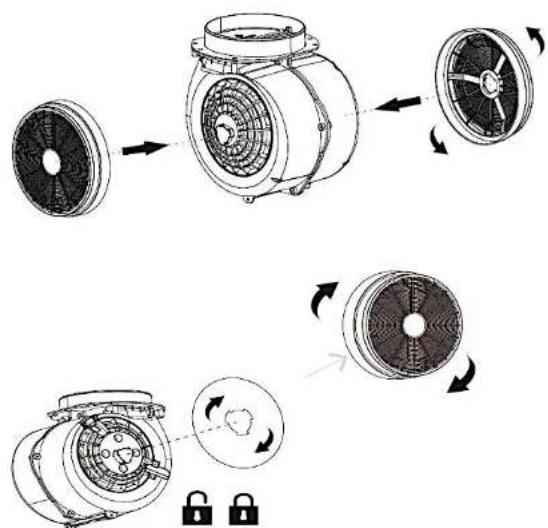
Carbon filter installation (Figure 15)
If using the recirculation system, it is recommended to install carbon filters. Carbon filters can filter unpleasant food colours from the environment.
- Remove the mesh filters before installing the carbon filters.
- Place the carbon filter on the fan housing shaft by aligning the carbon filter holes with the housing shaft.
- Rotate the carbon filter clockwise.
- Turn until it cannot move further. Turn the carbon filter cover anticlockwise to remove it.
- Finally, reinstall the mesh filters.
Note:
- Make sure the filter is properly locked, otherwise it could become loose and pose a hazard.
- When carbon filters are installed, the suction power decreases.
- Carbon filter dimensions: Face A diameter 12.9 cm; Face B diameter 13.3 cm.
IMPORTANT: Install carbon filters only if using the hood in air recirculation mode (WITHOUT EXTERNAL EXHAUST DUCT).
It is recommended to replace carbon filters regularly, depending on usage time, when a decrease in odour absorption properties is noticed.
Power cord installation
You must connect the plug to a 220-240 V\~, 50/60 Hz power line.
The extractor hood must be connected to an earthed installation.
ENGLISHENGLISH
4. OPERATION
In standby mode, the power on/off touch icon has 50% brightness while other touch icons are invisible. When the hood is connected, the buzzer will sound twice, and all button indicators (except On/Off) and the display will illuminate for 1 second, then turn off as the hood enters standby mode.
Power on/off touch icon
In standby mode, a short press of this icon will activate all touch icons, and the hood will start at low speed.
Press again and the extractor hood will switch off. After plugging in the extractor hood, it starts at low speed.
The next time you switch on the hood, it will remember the speed at which it was last operating.
Note: In operating mode, all icons have 100% brightness.
Light on/off touch icon
Press the light touch icon to switch on the extractor hood light.
Press again to switch it off.
Speed touch icons
When the appliance is in operating mode, press the icon to operate at low/medium/high speed, cycling through (low -> medium -> high -> low...).
A long press of the + icon will activate the Booster (Intensive) function.
The digital display will show a flashing "B". After 5 minutes, it will return to high speed.
Delay function
When the extractor hood is operating, press and hold the + and - icons. The digital display will show the current speed and flash, indicating that the extractor hood has entered delayed shutdown mode.
The delay time is 5 minutes. During the countdown, a long press of the - and + icons can cancel the delay function.
After 5 minutes, all indicator lights will turn off, the digital display will continue flashing, and
the hood will emit continuous beeps.
Press any icon to stop the buzzer sound and return to standby mode.
Note: If no operation is performed, it will automatically return to standby mode after 5 seconds.
Gesture control sensors
In standby mode, move your hand from left to right to activate low speed.
At low speed, move your hand from left to right to activate medium speed.
At medium speed, move your hand from left to right to activate high speed.
At high speed, move your hand from left to right to activate Booster (Intensive) speed.
In operating mode, move your hand from right to left to activate the Delay function. During the 5-minute countdown, move your hand from right to left again and the extractor hood will switch off.
Note: Only hoods installed with gesture control function can be activated by gesture control.
- TROUBLESHOOTING
| Problem Possible causes | Possible solution | |
| The light turns on, but the motor does not run. | The ventilation system is blocked. | Clear the obstruction. |
| The capacitor is faulty. Contact Cecotec's Official Technical Support Service. | ||
| The motor is faulty. Contact Cecotec's Official Technical Support Service. | ||
| The light does not turn on and the motor does not run. | The LED light does not work. | Replace the LED light bulb. |
| The plug is loose. Make sure the plug is properly connected to the power socket. | ||
| The extractor hood vibrates. | The fan is damaged. Contact Cecotec's Official Technical Support Service. | |
| The motor is not properly secured. | Contact Cecotec's Official Technical Support Service. | |
| The hood is not properly fixed to the wall. | Make sure the extractor hood is completely secure. | |
ENGLISHENGLISH
| Smoke or steam cannot be properly extracted. | The distance between the extractor hood and the hob is too great. | Reduce the distance between the hood and the hob. |
| The hob is exposed to a high airflow. | Reduce the airflow in the cooking area by closing doors or windows. |
6. CLEANING AND MAINTENANCE
Cleaning and maintenance
Switch off the extractor hood and unplug it from the mains socket before performing any cleaning or maintenance tasks. The hood's external surfaces are susceptible to scratches and stains. Therefore, use mild cleaning products and remove any alkaline or acidic substance residues (lemon juice, vinegar) immediately.
Stainless steel surfaces
Stainless steel must be cleaned regularly to ensure a long service life. To do this, use a suitable cleaner.
Control panel surface
The control panel can be cleaned with a damp cloth and a neutral cleaning product.
Make sure the cloth is clean and well wrung out before cleaning the extractor hood. Use a soft, dry cloth to remove any excess moisture that may remain after cleaning.
Mesh filter cleaning
Clean the filter every month to prevent fire hazards. The filter accumulates grease, smoke and dust, which affects the efficiency of the extractor hood. If the filter is not cleaned, grease residues will accumulate. Clean the filter with water and a suitable cleaning product, allow it to air dry before replacing it.
7. RECYCLING OF ELECTRICAL AND ELECTRONIC EQUIPMENT

This symbol indicates that, according to the applicable regulations, the product and/or battery must be disposed of separately from household waste. When this product reaches the end of its shelf life, you should dispose of the batteries/accumulators and take them to a collection point designated by the local authorities.
For detailed information on how to properly dispose of electrical and electronic equipment
and/or the corresponding batteries, consumers should contact their local authorities. Compliance with the above guidelines will help protecting the environment.
Information regarding national packaging recycling systems and their marking can be found on our website.
B. COPYRIGHT
The intellectual property rights over the texts in this manual belong to CECOTEC INNOVACIONES, S.L. All rights reserved. The content of this publication may not, either in part or in its entirety, be reproduced, stored in a retrieval system, transmitted or distributed by any means (electronic, mechanical, photocopying, recording or similar) without prior authorisation from CECOTEC INNOVACIONES, S.L.
9. SIMPLIFIED EU DECLARATION OF CONFORMITY
CE Cecotec Innovaciones hereby declares that this appliance complies with the essential requirements and other relevant provisions of applicable European Union regulations. This appliance has been designed, manufactured and tested in compliance with required safety and quality standards. The full text of the EU Declaration of Conformity can be found on the following website: https://cecotec.es/es/information/declaration-of-conformity
FRANÇAISFRANÇAIS
1. PIÈCES ET COMPOSANTS
Panneau de contrôle
Image 1
يَنْتَكُ: https://cecotec.es/es/information/declaration-of-conformity
1234567
Fig./Img./Abb./Afo./Rys./Obr./Şekil/Eik./ábra/1
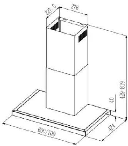
Fig./Img./Abb./Afo./Rys./Obr./Şekil/Eik./ábra/12
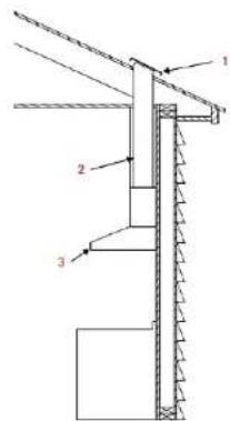
Fig./img./Abb./Afb./Rys./Obr./Şekil/Eik./ábra/Ükülü3
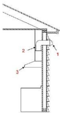
Fig./Img./Abb./Afb./Rys./Obr./Şekil/Eik./ábra/4
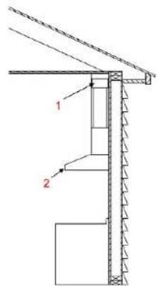
Fig./img./Abb./Afb./Rys./Obr./Şekil/Eik./âbrə/Ükışlı5
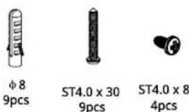
Fig./Img./Abb./Afb./Rys./Obr./Şekil/Eik./ábra/16
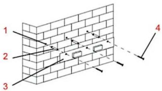
Fig./Img./Abb./Afb./Rys./Obr./Şekil/Eik./śbra/UJ4U7
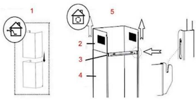
Fig./Img./Abb./Afb/Rys./Obr./Şekil/Eik./abra/###9
natural_image
Technical line drawing of a mechanical device mounted on a base plate against a brick wall background (no text or symbols)Fig./Img./Abb./Afo./Rys./Obr./Şekil/Eik./ábra/18
natural_image
Diagram of a mechanical assembly with two hanging weights on a brick wall (no text or symbols)Fig./Img./Abb./Afb./Rys./Obr./Şekil/Eik./ábra/10
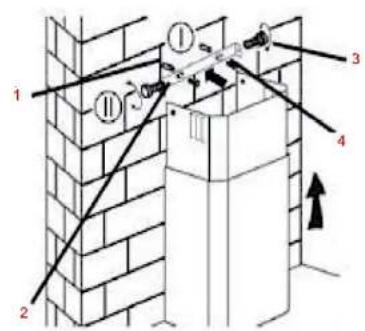
Fig./Img./Abb./Afb./Rys./Obr./Şekil/Eik./ábra/11

natural_image
Technical line drawing of a brick wall with a rectangular base and dimension labels (no text or symbols)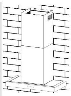
natural_image
Technical line drawing of a brick wall structure with a vertical support frame (no text or symbols)Fig./Img./Abb./Afb./Rys./Obr./Şekil/Eik./ábra/UJ4U12
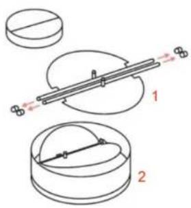
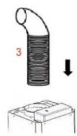
Fig./Img./Abb./Afb./Rys./Obr./Şekil/Eik./ábra/üklı13
natural_image
Technical line drawing of a ceiling-mounted device with internal components and a separate schematic view (no text or symbols)Fig./Img./Abb./Afb./Rys./Obr./Şekil/Eik./âbrə/14
natural_image
Technical illustration of a mechanical fan assembly showing three stages: top view, middle view, and bottom view with no visible text or symbols.Fig./Img./Abb./Afb./Rys./Obr./Şekil/Eik./ábra/15
www.cecotec.es