
All Easy Pro 24 - Air-conditioner MIDEA - Free user manual and instructions
Find the device manual for free All Easy Pro 24 MIDEA in PDF.

| Product type | Wall-mounted split air conditioner |
| Brand | Midea |
| Model | All Easy Pro 24 |
| Cooling capacity | 7.0 kW (24,000 BTU/h) |
| Heating capacity | 7.5 kW (estimated) |
| Refrigerant | R32 |
| Refrigerant GWP | 675 |
| Energy class cooling | A+++ |
| Energy class heating | A++ |
| SEER (cooling) | 8.6 |
| SCOP (average season heating) | 4.6 |
| Indoor sound power level | 58 dB (cooling) |
| Outdoor sound power level | 64 dB (cooling) |
| Power supply | 220-240 V ~ 50 Hz |
| Indoor unit dimensions (W x H x D) | Approx. 1140 x 322 x 240 mm |
| Outdoor unit dimensions (W x H x D) | Approx. 946 x 810 x 420 mm |
| Indoor unit weight | Approx. 15 kg |
| Outdoor unit weight | Approx. 50 kg |
| Maximum pipe length | 50 m |
| Maximum elevation difference | 25 m |
| Main functions | Active cleaning, Distant breeze, Intelligent ECO eye, Auto restart, Anti-mold, Timer, Sleep, Wireless control |
| Filter maintenance | Washable air filter with soapy water |
| Repairability index | Not communicated |
Frequently Asked Questions - All Easy Pro 24 MIDEA
User questions about All Easy Pro 24 MIDEA
0 question about this device. Answer the ones you know or ask your own.
Ask a new question about this device
Download the instructions for your Air-conditioner in PDF format for free! Find your manual All Easy Pro 24 - MIDEA and take your electronic device back in hand. On this page are published all the documents necessary for the use of your device. All Easy Pro 24 by MIDEA.
USER MANUAL All Easy Pro 24 MIDEA
natural_image
Line drawing of a rectangular electronic device with a handle and mounting bracket (no text or symbols)Read this manual carefully before installing or operating your new air conditioning unit. Make sure to save this manual for future reference.
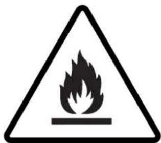
CAUTION: Risk of fire
IMPORTANT NOTE:
Read this manual carefully before installing or operating your new air conditioning unit. Make sure to save this manual for future reference.
Table of Contents
Safety Precautions 04
Owner's Manual
Unit Specifications and Features....08
- Indoor unit display....08
- Operating temperature....09
- Other features ....10
- Setting angle of airflow....11
- Manual operation (without Remote)....11
Care and Maintenance....12
Troubleshooting....14
Installation Manual
Accessories....17
Installation Summary - Indoor Unit ....18
Unit Parts....19
Indoor Unit Installation....20
- Select installation location....20
- Attach mounting plate to wall....20
- Drill wall hole for connective piping....21
- Prepare refrigerant piping....22
- Connect drain hose....24
- Connect signal cable....25
- Wrap piping and cables....26
- Mount indoor unit....27
Outdoor Unit Installation....27
- Select installation location....27
- Install drain joint....28
- Anchor outdoor unit....28
- Connect signal and power cables....30
Refrigerant Piping Connection....31
A. Note on Pipe Length....31
B. Connection Instructions –Refrigerant Piping....31
1. Cut pipe....31
2. Remove burrs....32
3. Flare pipe ends....32
4. Connect pipes....32
Air Evacuation....35
- Evacuation Instructions....35
- Note on Adding Refrigerant....36
Electrical and Gas Leak Checks....37
Test Run....38
Safety Precautions
Read Safety Precautions Before Operation and Installation
Incorrect installation due to ignoring instructions can cause serious damage or injury.
The seriousness of potential damage or injuries is classified as either a WARNING or CAUTION.

WARNING
This symbol indicates the possibility of personnel injury or loss of life.

CAUTION
This symbol indicates the possibility of property damage or serious consequences.

WARNING
This appliance can be used by children aged from 8 years and above and persons with reduced physical, sensory or mental capabilities or lack of experience and knowledge if they have been given supervision or instruction concerning use of the appliance in a safe way and understand the hazards involved. Children shall not play with the appliance. Cleaning and user maintenance shall not be made by children without supervision(EN Standard requirements).
This appliance is not intended for use by persons(including children) with reduced physical, sensory or mental capabilities, or lack of experience and knowledge, unless they have been given supervision or instruction concerning use of the appliance by a person responsible for their safety. Children should be supervised to ensure that they do not play with the appliance.

WARNINGS FOR PRODUCT USE
- If an abnormal situation arises (like a burning smell), immediately turn off the unit and disconnect the power. Call your dealer for instructions to avoid electric shock, fire or injury.
- Do not insert fingers, rods or other objects into the air inlet or outlet. This may cause injury, since the fan may be rotating at high speeds.
- Do not use flammable sprays such as hair spray, lacquer or paint near the unit. This may cause fire or combustion.
- Do not operate the air conditioner in places near or around combustible gases. Emitted gas may collect around the unit and cause explosion.
- Do not operate your air conditioner in a wet room such as a bathroom or laundry room. Too much exposure to water can cause electrical components to short circuit.
- Do not expose your body directly to cool air for a prolonged period of time.
- Do not allow children to play with the air conditioner. Children must be supervised around the unit at all times.
- If the air conditioner is used together with burners or other heating devices, thoroughly ventilate the room to avoid oxygen deficiency.
- In certain functional environments, such as kitchens, server rooms, etc., the use of specially designed air-conditioning units is highly recommended.
CLEANING AND MAINTENANCE WARNINGS
- Turn off the device and disconnect the power before cleaning. Failure to do so can cause electrical shock.
- Do not clean the air conditioner with excessive amounts of water.
- Do not clean the air conditioner with combustible cleaning agents. Combustible cleaning agents can cause fire or deformation.

CAUTION
- Turn off the air conditioner and disconnect the power if you are not going to use it for a long time.
- Turn off and unplug the unit during storms.
• Make sure that water condensation can drain unhindered from the unit. - Do not operate the air conditioner with wet hands. This may cause electric shock.
- Do not use device for any other purpose than its intended use.
- Do not climb onto or place objects on top of the outdoor unit.
- Do not allow the air conditioner to operate for long periods of time with doors or windows open, or if the humidity is very high.

ELECTRICAL WARNINGS
- Only use the specified power cord. If the power cord is damaged, it must be replaced by the manufacturer, its service agent or similarly qualified persons in order to avoid a hazard.
- Keep power plug clean. Remove any dust or grime that accumulates on or around the plug. Dirty plugs can cause fire or electric shock.
- Do not pull power cord to unplug unit. Hold the plug firmly and pull it from the outlet. Pulling directly on the cord can damage it, which can lead to fire or electric shock.
- Do not modify the length of the power supply cord or use an extension cord to power the unit.
- Do not share the electrical outlet with other appliances. Improper or insufficient power supply can cause fire or electrical shock.
- The product must be properly grounded at the time of installation, or electrical shock may occur.
- For all electrical work, follow all local and national wiring standards, regulations, and the Installation Manual. Connect cables tightly, and clamp them securely to prevent external forces from damaging the terminal. Improper electrical connections can overheat and cause fire, and may also cause shock. All electrical connections must be made according to the Electrical Connection Diagram located on the panels of the indoor and outdoor units.
- All wiring must be properly arranged to ensure that the control board cover can close properly. If the control board cover is not closed properly, it can lead to corrosion and cause the connection points on the terminal to heat up, catch fire, or cause electrical shock.
- If connecting power to fixed wiring, an all-pole disconnection device which has at least 3mm clearances in all poles, and have a leakage current that may exceed 10mA, the residual current device(RCD) having a rated residual operating current not exceeding 30mA, and disconnection must be incorporated in the fixed wiring in accordance with the wiring rules.
TAKE NOTE OF FUSE SPECIFICATIONS
The air conditioner's circuit board (PCB) is designed with a fuse to provide overcurrent protection. The specifications of the fuse are printed on the circuit board, such as :
Indoor unit: T3.15AL/250VAC, T5AL/250VAC, T3.15A/250VAC, T5A/250VAC, etc.
Outdoor unit: T20A/250VAC(<=18000Btu/h units), T30A/250VAC(>18000Btu/h units)
NOTE: For the units with R32 or R290 refrigerant, only the blast-proof ceramic fuse can be used.

WARNINGS FOR PRODUCT INSTALLATION
- Installation must be performed by an authorized dealer or specialist. Defective installation can cause water leakage, electrical shock, or fire.
- Installation must be performed according to the installation instructions. Improper installation can cause water leakage, electrical shock, or fire.
(In North America, installation must be performed in accordance with the requirement of NEC and CEC by authorized personnel only.) - Contact an authorized service technician for repair or maintenance of this unit. This appliance shall be installed in accordance with national wiring regulations.
- Only use the included accessories, parts, and specified parts for installation. Using non-standard parts can cause water leakage, electrical shock, fire, and can cause the unit to fail.
- Install the unit in a firm location that can support the unit's weight. If the chosen location cannot support the unit's weight, or the installation is not done properly, the unit may drop and cause serious injury and damage.
- Install drainage piping according to the instructions in this manual. Improper drainage may cause water damage to your home and property.
- For units that have an auxiliary electric heater, do not install the unit within 1 meter (3 feet) of any combustible materials.
- Do not install the unit in a location that may be exposed to combustible gas leaks. If combustible gas accumulates around the unit, it may cause fire.
- Do not turn on the power until all work has been completed.
- When moving or relocating the air conditioner, consult experienced service technicians for disconnection and reinstallation of the unit.
- How to install the appliance to its support, please read the information for details in "indoor unit installation" and "outdoor unit installation" sections.
Note about Fluorinated Gasses(Not applicable to the unit using R290 Refrigerant)
- This air-conditioning unit contains fluorinated greenhouse gasses. For specific information on the type of gas and the amount, please refer to the relevant label on the unit itself or the "Owner's Manual - Product Fiche" in the packaging of the outdoor unit. (European Union products only).
- Installation, service, maintenance and repair of this unit must be performed by a certified technician.
- Product uninstallation and recycling must be performed by a certified technician.
- For equipment that contains fluorinated greenhouse gases in quantities of 5 tonnes of CO2 equivalent or more, but of less than 50 tonnes of CO2 equivalent, If the system has a leak-detection system installed, it must be checked for leaks at least every 24 months.
- When the unit is checked for leaks, proper record-keeping of all checks is strongly recommended.

WARNING for Using R32/R290 Refrigerant
- When flammable refrigerant are employed, appliance shall be stored in a well -ventilated area where the room size corresponds to the room area as specific for operation.
For R32 frigerant models:
Appliance shall be installed, operated and stored in a room with a floor area larger than 4m^2 . Appliance shall not be installed in an unvertilated space, if that space is smaller than 4m^2 .
For R290 refrigerant models, the minimum room size needed:
<=9000Btu/h units: 13m²
9000Btu/h and <=12000Btu/h units: 17m ^2
12000Btu/h and <=18000Btu/h units: 26m^2
18000Btu/h and <=24000Btu/h units: 35m^2
- Reusable mechanical connectors and flared joints are not allowed indoors.
(EN Standard Requirements).
- Mechanical connectors used indoors shall have a rate of not more than 3g/year at 25% of the maximum allowable pressure. When mechanical connectors are reused indoors, sealing parts shall be renewed. When flared joints are reused indoors, the flare part shall be re-fabricated. (UL Standard Requirements)
- When mechanical connectors are reused indoors, sealing parts shall be renewed. When flared joints are reused indoors, the flare part shall be re-fabricated.
(IEC Standard Requirements)
European Disposal Guidelines
This marking shown on the product or its literature, indicates that waste electrical and electrical equipment should not be mixed with general household waste.
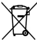

Correct Disposal of This Product
(Waste Electrical & Electronic Equipment)
This appliance contains refrigerant and other potentially hazardous materials. When disposing of this appliance, the law requires special collection and treatment. Do not dispose of this product as household waste or unsorted municipal waste.
When disposing of this appliance, you have the following options:
- Dispose of the appliance at designated municipal electronic waste collection facility.
- When buying a new appliance, the retailer will take back the old appliance free of charge.
- The manufacturer will take back the old appliance free of charge.
- Sell the appliance to certified scrap metal dealers.
Special notice
Disposing of this appliance in the forest or other natural surroundings endangers your health and is bad for the environment. Hazardous substances may leak into the ground water and enter the food chain.
Unit Specifications and Features
Indoor unit display
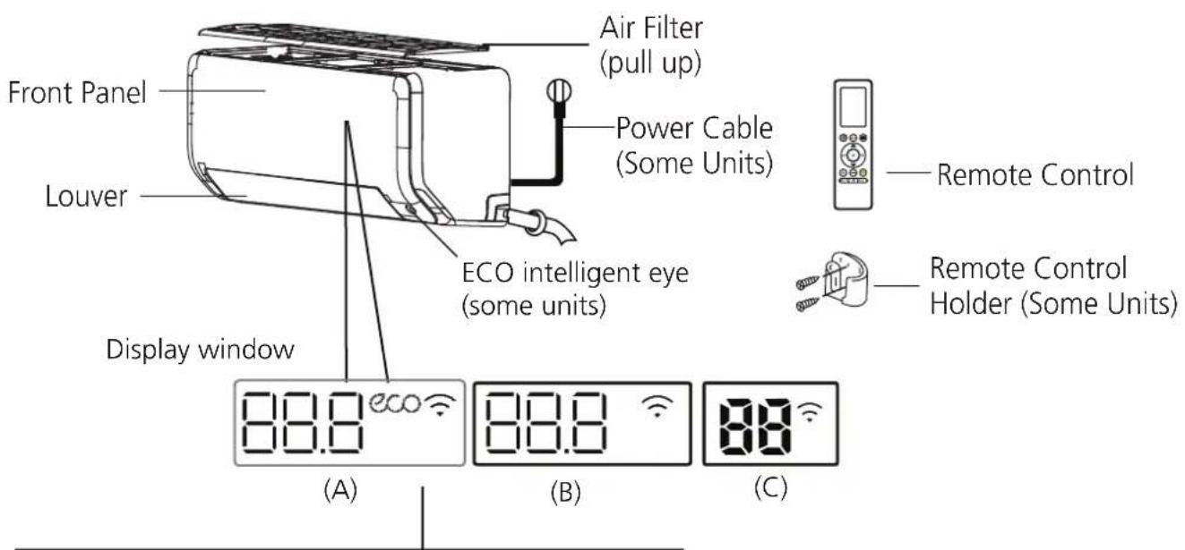
"88.8" "88" Displays temperature, operation feature and Error codes:
"ON" for 3 seconds when:
- TIMER ON is set (if the unit is OFF, "ON" remains on when TIMER ON is set)
- FRESH, SWING, TURBO, ECO, BREEZE AWAY, ECO INTELLIGENT EYE or SILENCE feature is turned on
"OF " for 3 seconds when:
- TIMER OFF is set
- FRESH, SWING, TURBO, ECO, BREEZE AWAY, ECO INTELLIGENT EYE or SILENCE feature is turned off
" dF " when defrosting(for cooling & heating units)
" " when Active Clean feature is turned on
"FP " when 8°C(46°F) heating mode is turned on(some units)
" ECO " when ECO feature is activated(some units)
" 🔊 " when wireless control feature is activated(some units)
NOTE: Different models have different front panel and display window. Not all the indicators describing below are available for the air conditioner you purchased. Please check the indoor display window of the unit you purchased.
Illustrations in this manual are for explanatory purposes. The actual shape of your indoor unit may be slightly different. The actual shape shall prevail.
Display Code Meanings
Operating temperature
When your air conditioner is used outside of the following temperature ranges, certain safety protection features may activate and cause the unit to disable.
Inverter Split Type
| COOL mode HEAT mode DRY mode | |||
| Room Temperature | 17°C - 32°C(62°F - 90°F) | 0°C - 30°C(32°F - 86°F) | 10°C - 32°C(50°F - 90°F) |
| Outdoor Temperature | 0°C - 50°C(32°F - 122°F) | -15°C - 24°C(5°F - 75°F) | 0°C - 50°C(32°F - 122°F) |
| -15°C - 50°C(5°F - 122°F)(For models with low temp. cooling systems.) | |||
| 0°C - 52°C(32°F - 126°F)(For special tropical models) | 0°C - 52°C(32°F - 126°F)(For special tropical models | ||
FOR OUTDOOR UNITS WITH BASEPAN HEATER OR CRANKCASE HEATER
When outside temperature is below 0^ C( 32^ F), we strongly recommend keeping the unit plugged in at all time to ensure smooth ongoing performance.
Fixed-speed Type
| COOL mode | HEAT mode | DRY mode | |
| Room Temperature | 17°C-32°C (62°F-90°F) | 0°C-30°C(32°F-86°F) | 10°C-32°C (50°F-90°F) |
| Outdoor Temperature | 18°C-43°C (64°F-109°F) | -7°C-24°C(19°F-75°F) | 11°C-43°C (52°F-109°F) |
| -7°C-43°C (19°F-109°F)(For models with low-temp cooling systems) | 18°C-43°C (64°F-109°F) | ||
| 18°C-52°C (64°F-126°F)(For special tropical models) | 18°C-52°C (64°F-126°F)(For special tropical models) |
NOTE: Room relative humidity less than 80%. If the air conditioner operates in excess of this figure, the surface of the air conditioner may attract condensation. Please sets the vertical air flow louver to its maximum angle (vertically to the floor), and set HIGH fan mode.
To further optimize the performance of your unit, do the following:
- Keep doors and windows closed.
- Limit energy usage by using TIMER ON and TIMER OFF functions.
- Do not block air inlets or outlets.
- Regularly inspect and clean air filters.
A guide on using the infrared remote is not included in this literature package. Not all the functions are available for the air conditioner, please check the indoor display and remote control of the unit you purchased.
Other Features
• Auto-Restart(some units)
If the unit loses power, it will automatically restart with the prior settings once power has been restored.
• Anti-mildew (some units)
When turning off the unit from COOL, AUTO (COOL), or DRY modes, the air conditioner will continue operate at very low power to dry up condensed water and prevent mildew growth.
- Wireless Control(some units)
Wireless control allows you to control your air conditioner using your mobile phone and a wireless connection.
For the USB device access, replacement, maintenance operations must be carried out by professional staff.
- Louver Angle Memory(some units)
When turning on your unit, the louver will automatically resume its former angle.
• Active Clean function
-- The Active Clean Technology washes away dust, mold, and grease that may cause odors when it adheres to the heat exchanger by automatically freezing and then rapidly thawing the frost. A "pi-pi" sound will be heard. The Active clean operation is used to produce more condensed water to improve the cleaning effect, and the cold air will blow out. After cleaning, the internal wind wheel then keeps operating with hot air to blow-dry the evaporator, thus preventing the growth of mold and keeping the inside clean.
-- When this function is turned on, the indoor unit display window appears "CL", after 20 to 45 minutes, the unit will turn off automatically and cancel Active Clean function.
- Breeze Away (some units)
This feature avoids direct air flow blowing on the body and make you feel indulging in silky coolness.
• Refrigerant Leakage Detection(some units)
The indoor unit will automatically display "ELOC" when it detects refrigerant leakage.
• ECO Intelligent eye(some units)
The system is controlled intelligently under Intelligent eye mode. It can detect the people's activities in the room. In cooling mode, when you are away for 30 minutes, the unit will automatically lower the frequency to save energy(for Inverter models only). And the unit will automatically start and resume operation if sensing human activity again.
- Sleep Operation
The SLEEP function is used to decrease energy use while you sleep (and don't need the same temperature settings to stay comfortable). This function can only be activated via remote control. And the Sleep function is not available in FAN or DRY mode.
When in COOL mode, the unit will increase the temperature by 1^ C ( 2^ F) after 1 hour, and will increase an additional 1^ C ( 2^ F) after another hour.
When in HEAT mode, the unit will decrease the temperature by 1^ C ( 2^ F) after 1 hour, and will decrease an additional 1^ C ( 2^ F) after another hour.
The sleep feature will stop after 8 hours and the system will keep running with final situation.
flowchart
graph LR
    A["Set temperature"] --> B["1hr"]
    B --> C["1hr"]
    C --> D["Keep running"]
    E["Cool mode(+1℃/2℉) per hour for the first two hours"] --> B
    F["Heat mode(-1℃/2℉) per hour for the first two hours"] --> C
    G["Saving energy during sleep"] --> H["Sun"]
NOTE:
For multi-split air conditioners, the following functions are not available:
Active clean function, Silence feature, Breeze away function, Refrigerant leakage detection function and Eco feature.
- Setting Angle of Air Flow
Setting vertical angle of air flow
While the unit is on, use the SWING button on remote control to set the direction (vertical angle) of airflow. Please refer to the Remote Control Manual for details.
NOTE ON LOUVER ANGLES
When using COOL or DRY mode, do not set louver at too vertical an angle for long periods of time. This can cause water to condense on the louver blade, which will drop on your floor or furnishings.
When using COOL or HEAT mode, setting the louver at too vertical an angle can reduce the performance of the unit due to restricted air flow.
Setting horizontal angle of air flow
The horizontal angle of the airflow must be set manually. Grip the deflector rod (See Fig.B) and manually adjust it to your preferred direction.
For some units, the horizontal angle of the airflow can be set by remote control. please refer to the Remote Control Manual.
Manual Operation(without remote)

CAUTION
The manual button is intended for testing purposes and emergency operation only. Please do not use this function unless the remote control is lost and it is absolutely necessary. To restore regular operation, use the remote control to activate the unit. Unit must be turned off before manual operation.
To operate your unit manually:
- Locate the MANUAL CONTROL button on the right-hand side panel of the unit.
- Press the MANUAL CONTROL button one time to activate FORCED AUTO mode.
- Press the MANUAL CONTROL button again to activate FORCED COOLING mode.
- Press the MANUAL CONTROL button a third time to turn the unit off.
Unit specifications and Features
NOTE: Do not move louver by hand. This will cause the louver to become out of sync. If this occurs, turn off the unit and unplug it for a few seconds, then restart the unit. This will reset the louver.
Fig. A

CAUTION
Do not put your fingers in or near the blower and suction side of the unit. The high-speed fan inside the unit may cause injury.
Fig. B
Fig. C
Care and Maintenance
Cleaning Your Indoor Unit

BEFORE CLEANING OR MAINTENANCE
ALWAYS TURN OFF YOUR AIR CONDITIONER SYSTEM AND DISCONNECT ITS POWER SUPPLY BEFORE CLEANING OR MAINTENANCE.

CAUTION
Only use a soft, dry cloth to wipe the unit clean. If the unit is especially dirty, you can use a cloth soaked in warm water to wipe it clean.
- Do not use chemicals or chemically treated cloths to clean the unit
- Do not use benzene, paint thinner, polishing powder or other solvents to clean the unit. They can cause the plastic surface to crack or deform.
- Do not use water hotter than 40°C (104°F) to clean the front panel. This can cause the panel to deform or become discolored.
Cleaning Your Air Filter
A clogged air filter can reduce the cooling efficiency of your unit, can also make the air flow irregular and too much noisy, so please clean the air filter as often as necessary. Once the abnormal noise of air flow is heard, please clean the air filter immediately.
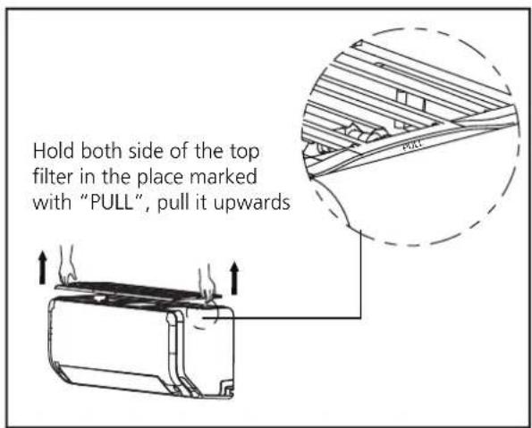
- The air filter is on the top of the air conditioner.
- Hold both side of the top filter in the place marked with "PULL", then pull it upwards.
- If your filter has small air freshening filters, unclip them from the larger filter. Clean these air freshening filters with a hand-held vacuum.
-
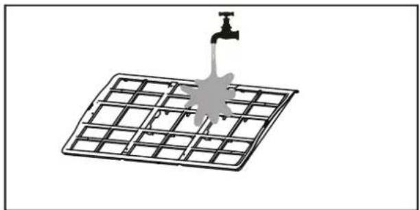
Clean the large air filter with warm, soapy water. Be sure to use a mild detergent.
-
Rinse the filter with fresh water, then shake off excess water.
- Dry it in a cool, dry place, and refrain from exposing it to direct sunlight.
- When dry, re-clip the air freshening filter to the larger filter, then install it back on the indoor unit.
natural_image
Diagram of a water tap spraying over a grid-patterned solar panel (no text or symbols)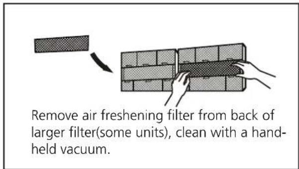

CAUTION
- Before changing the filter or cleaning, turn off the unit and disconnect its power supply.
- When removing filter, do not touch metal parts in the unit. The sharp metal edges can cut you.
- Do not use water to clean the inside of the indoor unit. This can destroy insulation and cause electrical shock.
- Do not expose filter to direct sunlight when drying. This can shrink the filter.
Air Filter Reminders (Optional)
Air Filter Cleaning Reminder
After 240 hours of use, the display window on the indoor unit will flash "CL." This is a reminder to clean your filter. After 15 seconds, the unit will revert to its previous display.
To reset the reminder, press the LED button on your remote control 4 times, or press the
MANUAL CONTROL button 3 times. If you don't reset the reminder, the "CL" indicator will flash again when you restart the unit.
Air Filter Replacement Reminder
After 2,880 hours of use, the display window on the indoor unit will flash "nF." This is a reminder to replace your filter. After 15 seconds, the unit will revert to its previous display.
To reset the reminder, press the LED button on your remote control 4 times, or press the
MANUAL CONTROL button 3 times. If you don't reset the reminder, the "nF" indicator will flash again when you restart the unit.

CAUTION
- Any maintenance and cleaning of outdoor unit should be performed by an authorized dealer or a licensed service provider.
- Any unit repairs should be performed by an authorized dealer or a licensed service provider.
Maintenance – Long Periods of Non-Use
If you plan not to use your air conditioner for an extended period of time, do the following:
natural_image
Diagram of a 3D rectangular block with shaded faces and an arrow indicating a dimension (no text or symbols)Clean all filters
natural_image
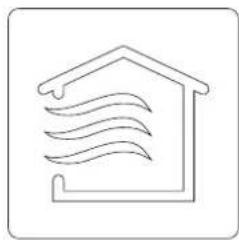
Simple line drawing of a house with wavy lines inside, no text or symbols presentTurn on FAN function until unit dries out completely
Turn off the unit aRemove batteries
disconnect the power
natural_image
Simple line drawing of a remote control with a handle and internal components (no text or symbols)from remote control
Maintenance – Pre-Season Inspection
After long periods of non-use, or before periods of frequent use, do the following:
natural_image
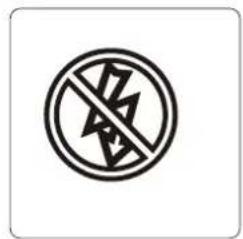
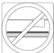
Cross-sectional diagram of a hazard symbol with lightning and ground symbols (no text or labels)Check for damaged wires Clean all filters
natural_image
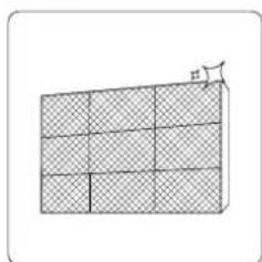
Diagram of a grid structure with shaded cells and an arrow pointing to a small figure (no text or symbols)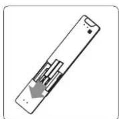
natural_image
Simple line drawing of a remote control device with an arrow indicating left-side motion (no text or symbols)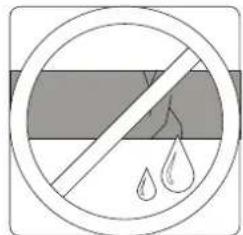
natural_image
Symbol of a prohibition sign with water droplets inside, no text or numbers presentCheck for leaks Replace batteries
Make sure nothing is blocking all air inlets and outlets
Troubleshooting

SAFETY PRECAUTIONS
If ANY of the following conditions occurs, turn off your unit immediately!
- The power cord is damaged or abnormally warm
- You smell a burning odor
- The unit emits loud or abnormal sounds
- A power fuse blows or the circuit breaker frequently trips
• Water or other objects fall into or out of the unit
DO NOT ATTEMPT TO FIX THESE YOURSELF! CONTACT AN AUTHORIZED SERVICE PROVIDER IMMEDIATELY!
Common Issues
The following problems are not a malfunction and in most situations will not require repairs.
Issue Possible Causes
| Unit does not turn on when pressing ON/OFF button | The Unit has a 3-minute protection feature that prevents the unit from overloading. The unit cannot be restarted within three minutes of being turned off. |
| The unit changes from COOL/HEAT mode to FAN mode | The unit may change its setting to prevent frost from forming on the unit. Once the temperature increases, the unit will start operating in the previously selected mode again. |
| The set temperature has been reached, at which point the unit turns off the compressor. The unit will continue operating when the temperature fluctuates again. | |
| The indoor unit emits white mist | In humid regions, a large temperature difference between the room's air and the conditioned air can cause white mist. |
| Both the indoor and outdoor units emit white mist | When the unit restarts in HEAT mode after defrosting, white mist may be emitted due to moisture generated from the defrosting process. |
| The indoor unit makes noises | A rushing air sound may occur when the louver resets its position. |
| A squeaking sound may occur after running the unit in HEAT mode due to expansion and contraction of the unit's plastic parts. | |
| Both the indoor unit and outdoor unit make noises | Low hissing sound during operation: This is normal and is caused by refrigerant gas flowing through both indoor and outdoor units. |
| Low hissing sound when the system starts, has just stopped running, or is defrosting: This noise is normal and is caused by the refrigerant gas stopping or changing direction. | |
| Squeaking sound: Normal expansion and contraction of plastic and metal parts caused by temperature changes during operation can cause squeaking noises. |
Issue Possible Causes
| The outdoor unit makes noises | The unit will make different sounds based on its current operating mode. |
| Dust is emitted from either the indoor or outdoor unit | The unit may accumulate dust during extended periods of non-use, which will be emitted when the unit is turned on. This can be mitigated by covering the unit during long periods of inactivity. |
| The unit emits a bad odor | The unit may absorb odors from the environment (such as furniture, cooking, cigarettes, etc.) which will be emitted during operations. |
| The unit's filters have become moldy and should be cleaned. | |
| The fan of the outdoor unit does not operate | During operation, the fan speed is controlled to optimize product operation. |
| Operation is erratic, unpredictable, or unit is unresponsive | Interference from cell phone towers and remote boosters may cause the unit to malfunction.In this case, try the following:Disconnect the power, then reconnect.Press ON/OFF button on remote control to restart operation. |
NOTE: If problem persists, contact a local dealer or your nearest customer service center. Provide them with a detailed description of the unit malfunction as well as your model number.
Troubleshooting
When troubles occur, please check the following points before contacting a repair company.
NOTE: If your problem persists after performing the checks and diagnostics above, turn off your unit immediately and contact an authorized service center.
Problem Possible Causes Solution
| Poor Cooling Performance | Temperature setting may be higher than ambient room temperature | Lower the temperature setting |
| The heat exchanger on the indoor or outdoor unit is dirty | Clean the affected heat exchanger | |
| The air filter is dirty | Remove the filter and clean it according to instructions | |
| The air inlet or outlet of either unit is blocked | Turn the unit off, remove the obstruction and turn it back on | |
| Doors and windows are open | Make sure that all doors and windows are closed while operating the unit | |
| Excessive heat is generated by sunlight | Close windows and curtains during periods of high heat or bright sunshine | |
| Too many sources of heat in the room (people, computers, electronics, etc.) | Reduce amount of heat sources | |
| Low refrigerant due to leak or long-term use | Check for leaks, re-seal if necessary and top off refrigerant | |
| SILENCE function is activated (optional function) | SILENCE function can lower product performance by reducing operating frequency. Turn off SILENCE function. | |
| Problem Possible Causes Solution | ||
| The unit is not working | Power failure | Wait for the power to be restored |
| The power is turned off Turn on | the power | |
| The fuse is burned out | Replace the fuse | |
| Remote control batteries are dead | Replace batteries | |
| The Unit's 3-minute protection has been activated | Wait three minutes after restarting the unit | |
| Timer is activated | Turn timer off | |
| The unit starts and stops frequently | There's too much or too little refrigerant in the system | Check for leaks and recharge the system with refrigerant. |
| Incompressible gas or moisture has entered the system. | Evacuate and recharge the system with refrigerant | |
| The compressor is broken Replace the compressor | ||
| The voltage is too high or too low | Install a manostat to regulate the voltage | |
| Poor heating performance | The outdoor temperature is extremely low | Use auxiliary heating device |
| Cold air is entering through doors and windows | Make sure that all doors and windows are closed during use | |
| Low refrigerant due to leak or long-term use | Check for leaks, re-seal if necessary and top off refrigerant | |
| Indicator lamps continue flashing | The unit may stop operation or continue to run safely. If the indicator lamps continue to flash or error codes appear, wait for about 10 minutes. The problem may resolve itself.If not, disconnect the power, then connect it again. Turn the unit on.If the problem persists, disconnect the power and contact your nearest customer service center. | |
| Error code appears and begins with the letters as the following in the window display of indoor unit:• E(x), P(x), F(x)• EH(xx), EL(xx), EC(xx)• PH(xx), PL(xx), PC(xx) | ||
Accessories
The air conditioning system comes with the following accessories. Use all of the installation parts and accessories to install the air conditioner. Improper installation may result in water leakage, electrical shock and fire, or cause the equipment to fail. The items are not included with the air conditioner must be purchased separately.
| Name of Accessories Name of Accessories | Name of Accessories | Share (pc) | Shape | ||
| Manual | 2-3 |  | Remote controller | 1 | 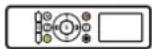 |
| Drain joint (for cooling & heating models) | 1 |  | Battery | 2 |  |
| Seal (for cooling & heating models) | 1 |  | Remote controller holder(optional) | 1 |  |
| Mounting plate | 1 | 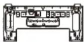 | Fixing screw for remote controller holder(optional) | 2 |  |
| Anchor | 5~8 (depending on models) |  | Small Filter (Need to be installed on the back of main air filter by the authorized technician while installing the machine) | 1~2 (depending on models) |  |
| Mounting plate fixing screw | 5~8 (depending on models) |  |
| Name | Shape Quantity(PC) | ||
| Connecting pipe assembly | Liquid side | Φ6.35(1/4in) | Parts you must purchase separately. Consult the dealer about the proper pipe size of the unit you purchased. |
| Φ9.52(3/8in) | |||
| Gas side | Φ9.52(3/8in) | ||
| Φ12.7(1/2in) | |||
| Φ16(5/8in) | |||
| Φ19(3/4in) | |||
| Magnetic ring and belt (if supplied, please refer to the wiring diagram to install it on the connective cable.) | 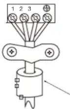 |  | Varies by model |
| Pass the belt through the hole of the Magnetic ring to fix it on the cable | |||
Installation Summary - Indoor Unit
Select Installation Location
natural_image
Pure mechanical diagram showing a lever mechanism with no text or symbolsDetermine Wall Hole Position
Attach Mounting Plate
Drill Wall Hole
natural_image
Diagram showing a mechanical tool interacting with a cylindrical component, no text or symbols presentConnect Piping
Connect Wiring (not applicable for some locations in the US)
natural_image
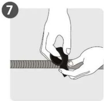
Illustration of hands holding a black object over a textured surface (no text or symbols)Prepare Drain Hose
natural_image
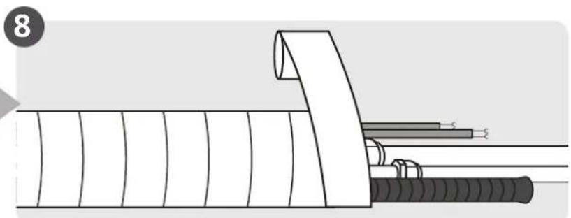
Diagram of a cable assembly with a coiled wire and clamped components (no text or symbols)Wrap Piping and Cable (not applicable for some locations in the US)
natural_image
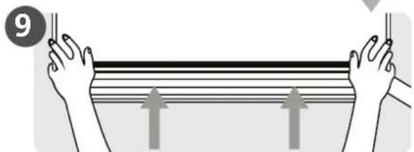
Illustration of hands holding a rectangular object with three upward arrows indicating motion or force (no text or symbols)Mount Indoor Unit
Unit Parts
NOTE: The installation must be performed in accordance with the requirement of local and national standards. The installation may be slightly different in different areas.
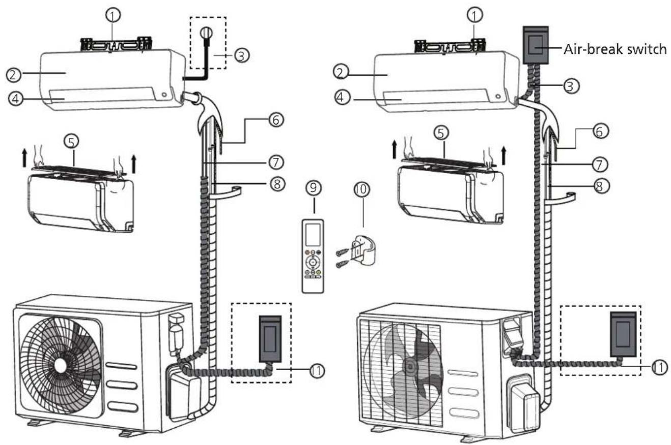
(1) (2)
① Wall Mounting Plate
② Front Panel
③ Power Cable (Some Units)
④ Louver
⑤ Air filter(pull it out)
⑥ Drainage Pipe
⑦ Signal Cable
⑧ Refrigerant Piping
⑨ Remote Controller
⑩ Remote Controller Holder (Some Units)
⑪ Outdoor Unit Power Cable (Some Units)
NOTE ON ILLUSTRATIONS
Illustrations in this manual are for explanatory purposes. The actual shape of your indoor unit may be slightly different. The actual shape shall prevail.
Indoor Unit Installation
Installation Instructions – Indoor unit
PRIOR TO INSTALLATION
Before installing the indoor unit, refer to the label on the product box to make sure that the model number of the indoor unit matches the model number of the outdoor unit.
Step 1: Select installation location
Before installing the indoor unit, you must choose an appropriate location. The following are standards that will help you choose an appropriate location for the unit.
Proper installation locations meet the following standards:
√ Good air circulation
√ Convenient drainage
√ Noise from the unit will not disturb other people
√ Firm and solid—the location will not vibrate
√ Strong enough to support the weight of the unit
A location at least one meter from all other electrical devices (e.g., TV, radio, computer)
DO NOT install unit in the following locations:
Near any source of heat, steam, or combustible gas
∅ Near flammable items such as curtains or clothing
∅ Near any obstacle that might block air circulation
∅ Near the doorway
∅ In a location subject to direct sunlight
NOTE ABOUT WALL HOLE:
If there is no fixed refrigerant piping:
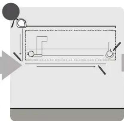
While choosing a location, be aware that you should leave ample room for a wall hole (see Drill wall hole for connective piping step) for the signal cable and refrigerant piping that connect the indoor and outdoor units. The default position for all piping is the right side of the indoor unit (while facing the unit). However, the unit can accommodate piping to both the left and right.
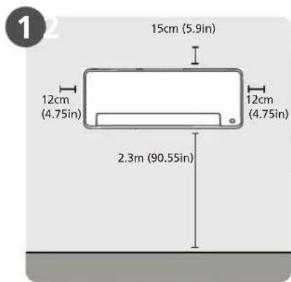
Refer to the following diagram to ensure proper distance from walls and ceiling:
Distance from ceiling is determined by the installation method.
NOTE:
- If no need the back holder to prop up the unit:
Finishing the pipe and cable connections before mount the indoor unit on the wall. If the instillation height is limited, 5cm from the ceiling is allowable, but this can lower product performance. To ensure enough space to install and remove the top air filter, keep at least 10cm or more from the ceiling.
- Need the back holder to prop up the unit: If connecting pipe and cable with front panel open, the minimum distance from ceiling is 22cm or more, if connecting pipe and cable without front panel(remove it), the minimum distance from ceiling is 11cm or more.
Step 2: Attach mounting plate to wall
The mounting plate is the device on which you will mount the indoor unit.
- Remove the screw that attaches the mounting plate to the back of the indoor unit.
- Secure the mounting plate to the wall with the screws provided. Make sure that mounting plate is flat against the wall.
NOTE FOR CONCRETE OR BRICK WALLS:
If the wall is made of brick, concrete, or similar material, drill 5mm-diameter (0.2in-diameter) holes in the wall and insert the sleeve anchors provided. Then secure the mounting plate to the wall by tightening the screws directly into the clip anchors.
Step 3: Drill wall hole for connective piping
-
Determine the location of the wall hole based on the position of the mounting plate. Refer to Mounting Plate Dimensions.
-
Using a 65mm (2.5in) or 90mm(3.54in) (depending on models) core drill, drill a hole in the wall. Make sure that the hole is drilled at a slight downward angle, so that the outdoor end of the hole is lower than the indoor end by about 5mm to 7mm (0.2-0.275in). This will ensure proper water drainage.
NOTE: When the gas side connective pipe is 16mm(5/8in) or more, the wall hole should be 90mm(3.54in).
- Place the protective wall cuff in the hole. This protects the edges of the hole and will help seal it when you finish the installation process.

CAUTION
When drilling the wall hole, make sure to avoid wires, plumbing, and other sensitive components.
MOUNTING PLATE DIMENSIONS
Different models have different mounting plates. For the convenience of installation, there are bubble level, carved dimensions on the mounting plate. Please install the plate and drill wall hole according to the information of the mounting plate. See the figures below.
Correct orientation of Mounting Plate
Unit: mm(inch)
Horizontal direction ruler
Vertical direction
ruler
CAUTION: The Bubble level on the mounting plate can't be removed. If it is broken, make sure to clean up the leaking liquid.

Model A
Model B
Model C
Step 4: Prepare refrigerant piping
The refrigerant piping is inside an insulating sleeve attached to the back of the unit. You must prepare the piping before passing it through the hole in the wall. Refer to the Refrigerant Piping
Connection section of this manual for detailed instructions on pipe flaring and flare torque requirements, technique, etc.
NOTE ON PIPING ANGLE
Refrigerant piping can exit the indoor unit from four different angles:
- Left-hand side
- Left rear
- Right-hand side
- Right rear
Refer to figures below for details.
natural_image
Technical line drawing of two identical electrical enclosure units with metal clamps and wiring (no text or symbols)NOTE ON PIPING CONNECTING
- In some locations of US, a conduit tube must be used to connect the cable. To ensure an enough space for the pipes running and the machine is against the wall after installation, It is recommended to attach the drain hose to the right-hand side (when you're facing the back of the unit).
- When choose Left-hand side or Right-hand side piping, please make sure that the pipes come out horizontally so as not to affect the lower panel installation.

CAUTION
Be extremely careful not to dent or damage the piping while bending them away from the unit. Any dents in the piping will affect the unit's performance.
If refrigerant piping is already embedded in the wall, do the following:
Step 1: Hook the indoor unit on the mounting plate:
- Keep in mind that the hooks on the mounting plate are smaller than the holes on the back of the unit. If you find that you don't have ample room to connect embedded pipes to the indoor unit, the unit can be adjusted left or right by about 30-50mm (1.25-1.95in), depending on the model.
Step 2: Prepare refrigerant piping:
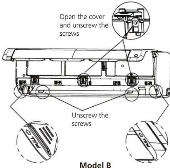
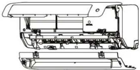
- Open and fix the position of the panel, then, open the covers of the two lock blocks, unscrew the screw showed in the picture below, then hold both sides of the lower panel in the place marked "PULL", pull it upwards to release the buckles, then take the lower panel down.
Model A
- Use the holder at the back of the unit to prop up the unit, giving you enough room to connect the refrigerant piping, signal cable, and drain hose.
natural_image
Technical line drawing of a mechanical assembly with an inset close-up showing internal components (no text or symbols)Use the holder at the back of the unit against on the mounting plate to prop up the unit
Step 3. Connect drain hose and refrigerant piping (refer to Refrigerant Piping Connection section of this manual for instructions).
Step 4. Keep pipe connection point exposed to perform the leak test (refer to Electrical Checks and Leak Checks section of this manual).
Step 5. After the leak test, wrap the connection point with insulation tape.
Step 6. Remove the bracket or wedge that is propping with insulation tape.
Step 7. Using even pressure, push down on the bottom half of the unit. Keep pushing down until the unit snaps onto the hooks along the bottom of the mounting plate.
If there is no refrigerant piping embedded in the wall, do the following:
- Based on the position of the wall hole relative to the mounting plate, choose the side from which the piping will exit the unit.
- If the wall hole is behind the unit, keep the knock-out panel in place. If the wall hole is to the side of the indoor unit, remove the plastic knock-out panel from that side of the unit. (See figure below). This will create a slot through which your piping can exit the unit. Use needle nose pliers if the plastic panel is too difficult to remove by hand.
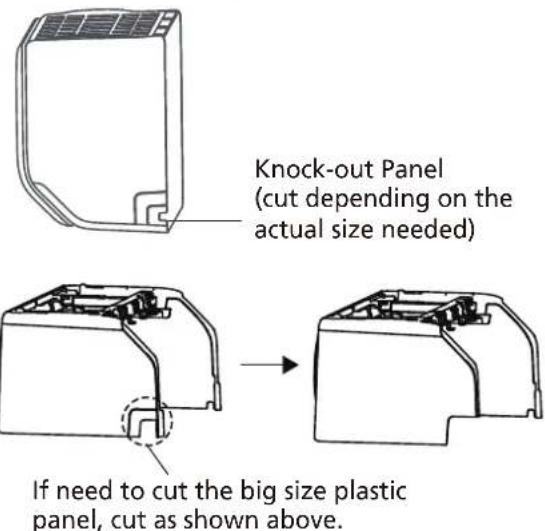
- Use scissors to cut down the length of the insulating sleeve to reveal about 40mm (1.57in) of the refrigerant piping. This serves two purposes:
- To facilitate the Refrigerant Piping Connection process. - To facilitage Gas Leak Checks and enable you to check for dents
-
Use the holder at the back of the unit to prop up the unit, giving you enough room to connect the refrigerant piping, signal cable, and drain hose.
-
Connect the indoor unit's refrigerant piping to the connective piping that will join the indoor and outdoor units. Refer to the Refrigerant Piping Connection section of this manual for detailed instructions.
-
Based on the position of the wall hole relative to the mounting plate, determine the necessary angle of your piping.
-
Grip the refrigerant piping at the base of the bend.
- Slowly, with even pressure, bend the piping towards the hole. Do not dent or damage the piping during the process.
Step 5: Connect drain hose
By default, the drain hose is attached to the left-hand side of unit (when you're facing the back of the unit). However, it can also be attached to the right-hand side. To ensure proper drainage, attach the drain hose on the same side that your refrigerant piping exits the unit.
- Wrap the connection point firmly with Teflon tape to ensure a good seal and to prevent leaks.
- Remove the air filter and pour a small amount of water into the drain pan to make sure that water flows from the unit smoothly.

NOTE ON DRAIN HOSE PLACEMENT
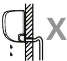
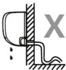
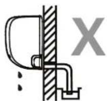
Make sure to arrange the drain hose according to the following figures.
DO NOT kink the drain hose.
DO NOT create a water trap.
DO NOT put the end of drain hose in water or a container that will collect water.
natural_image
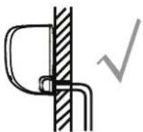
Pure mechanical diagram showing a bracket and vertical wall with a checkmark (no text or symbols)CORRECT
Make sure there are no kinks or dent in drain hose to ensure proper drainage.
natural_image
Simple line drawing of a mechanical joint or bracket with a vertical hatched section and a labeled X (no text or symbols)NOT CORRECT
Kinks in the drain hose will create water traps.
natural_image
Simple line drawing of a wall-mounted device with a bracket and grounding, no text or symbols presentNOT CORRECT
Kinks in the drain hose will create water traps.
natural_image
Simple line drawing of a door latch connected to a wall, with no text or symbols present.NOT CORRECT
Do not place the end of the drain hose in water or in containers that collect water. This will prevent proper drainage.
PLUG THE UNUSED DRAIN HOLE
To prevent unwanted leaks you must plug the unused drain hole with the rubber plug provided.

BEFORE PERFORMING ANY ELECTRICAL WORK, READ THESE REGULATIONS
- All wiring must comply with local and national electrical codes, regulations and must be installed by a licensed electrician.
- All electrical connections must be made according to the Electrical Connection Diagram located on the panels of the indoor and outdoor units.
- If there is a serious safety issue with the power supply, stop work immediately. Explain your reasoning to the client, and refuse to install the unit until the safety issue is properly resolved.
- Power voltage should be within 90-110% of rated voltage. Insufficient power supply can cause malfunction, electrical shock, or fire.
- If connecting power to fixed wiring, install a surge protector and main power switch with a capacity of 1.5 times the maximum current of the unit.
- If connecting power to fixed wiring, a switch or circuit breaker that disconnects all poles and has a contact separation of at least 1/8in (3mm) must be incorporated in the fixed wiring. The qualified technician must use an approved circuit breaker or switch.
- Only connect the unit to an individual branch circuit outlet. Do not connect another appliance to that outlet.
- Make sure to properly ground the air conditioner.
- Every wire must be firmly connected. Loose wiring can cause the terminal to overheat, resulting in product malfunction and possible fire.
- Do not let wires touch or rest against refrigerant tubing, the compressor, or any moving parts within the unit.
- If the unit has an auxiliary electric heater, it must be installed at least 1 meter (40in) away from any combustible materials.
- To avoid getting an electric shock, never touch the electrical components soon after the power supply has been turned off. After turning off the power, always wait 10 minutes or more before you touch the electrical components.

WARNING
BEFORE PERFORMING ANY ELECTRICAL OR WIRING WORK, TURN OFF THE MAIN POWER TO THE SYSTEM.
Step 6: Connect signal cable
The signal cable enables communication between the indoor and outdoor units. You must first choose the right cable size before preparing it for connection.
Cable Types
- Indoor Power Cable (if applicable): H05VV-F or H05V2V2-F
• Outdoor Power Cable: H07RN-F
• Signal Cable: H07RN-F
Minimum Cross-Sectional Area of Power and Signal Cables (For reference)
| Rated Current of Appliance (A) | Nominal Cross-Sectional Area (mm2) |
| >3 and ≤6 | 0.75 |
| >6 and ≤10 | 1 |
| >10 and ≤16 | 1.5 |
| >16 and ≤25 | 2.5 |
| >25 and ≤32 | 4 |
| >32 and ≤40 | 6 |
CHOOSE THE RIGHT CABLE SIZE
The size of the power supply cable, signal cable, fuse, and switch needed is determined by the maximum current of the unit. The maximum current is indicated on the nameplate located on the side panel of the unit. Refer to this nameplate to choose the right cable, fuse, or switch.
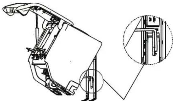
- Open and fix the position of the panel, then, open the covers of the two lock blocks, unscrew the screw showed in the picture below, then hold both sides of the lower panel in the place marked "PULL", pull it upwards to release the buckles, then take the lower panel down.
- Open the wire box cover to connect the cable.
natural_image
Technical line drawing of a printer internal structure (no text or symbols)First open the front panel, then remove the lower panel.

WARNING
ALL WIRING MUST BE PERFORMED STRICTLY IN ACCORDANCE WITH THE WIRING DIAGRAM LOCATED ON THE BACK OF THE INDOOR UNIT'S FRONT PANEL.
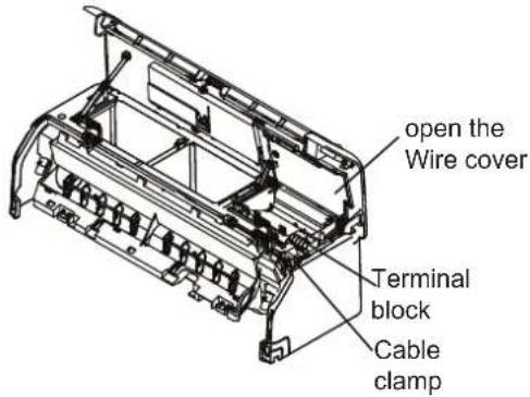
- Unscrew the cable clamp below the terminal block and place it to the side.
- Facing the back of the unit, remove the plastic panel on the bottom left-hand side.
- Feed the signal wire through this slot, from the back of the unit to the front.
- Facing the front of the unit, connect the wire according to the indoor unit's wiring diagram, connect the u-lug and firmly screw each wire to its corresponding terminal.

CAUTION
DO NOT MIX UP LIVE AND NULL WIRES
This is dangerous, and can cause the air conditioning unit to malfunction.
- After checking to make sure every connection is secure, use the cable clamp to fasten the signal cable to the unit. Screw the cable clamp down tightly.
- Replace the wire cover on the front of the unit, and the plastic panel on the back.

NOTE ABOUT WIRING
THE WIRING CONNECTION PROCESS MAY DIFFER SLIGHTLY BETWEEN UNITS AND REGIONS.
Step 7: Wrapping and cables
Before passing the piping, drain hose, and the signal cable through the wall hole, you must bundle them together to save space, protect them, and insulate them (This may not applicable for some locations in US).
- Bundle the drain hose, refrigerant pipes, and signal cable as shown below:
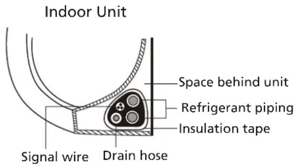
DRAIN HOSE MUST BE ON BOTTOM
Make sure that the drain hose is at the bottom of the bundle. Putting the drain hose at the top of the bundle can cause the drain pan to overflow, which can lead to fire or water damage.
DO NOT INTERTWINE SIGNAL CABLE WITH OTHER WIRES
While bundling these items together, do not intertwine or cross the signal cable with any other wiring.
- Using adhesive vinyl tape, attach the drain hose to the underside of the refrigerant pipes.
- Using insulation tape, wrap the signal wire, refrigerant pipes, and drain hose tightly together. Double-check that all items are bundled.
DO NOT WRAP ENDS OF PIPING
When wrapping the bundle, keep the ends of the piping unwrapped. You need to access them to test for leaks at the end of the installation process (refer to Electrical Checks
Step 8: Mount indoor unit
If you installed new connective piping to the outdoor unit, do the following:
- If you have already passed the refrigerant piping through the hole in the wall, proceed to Step 4.
- Otherwise, double-check that the ends of the refrigerant pipes are sealed to prevent dirt or foreign materials from entering the pipes.
- Slowly pass the wrapped bundle of refrigerant pipes, drain hose, and signal wire through the hole in the wall.
- Hook the top of the indoor unit on the upper hook of the mounting plate.
- Check that unit is hooked firmly on mounting by applying slight pressure to the left and right-hand sides of the unit. The unit should not jiggle or shift.
- Using even pressure, push down on the bottom half of the unit. Keep pushing down until the unit snaps onto the hooks along the bottom of the mounting plate.
- Again, check that the unit is firmly mounted by applying slight pressure to the left and the right-hand sides of the unit.
Outdoor Unit Installation
Install the unit by following local codes and regulations, there may be differ slightly between different regions.
Installation Instructions – Outdoor unit
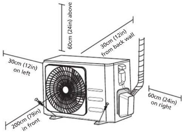
Step 1: Select installation location
Before installing the outdoor unit, you must choose an appropriate location. The following are standards that will help you choose an appropriate location for the unit.
Proper installation locations meet the following standards:
√ Meets all spatial requirements shown in Installation Space Requirements above.
√ Good air circulation and ventilation
☑ Firm and solid—the location can support the unit and will not vibrate
☑ Noise from the unit will not disturb others
√ Protected from prolonged periods of direct sunlight or rain
√ Where snowfall is anticipated, raise the unit above the base pad to prevent ice buildup and coil damage. Mount the unit high enough to be above the average accumulated area snowfall. The minimum height must be 18 inches
DO NOT install unit in the following locations:
∅ Near an obstacle that will block air inlets and outlets
Near a public street, crowded areas, or where noise from the unit will disturb others
Near animals or plants that will be harmed by hot air discharge
∅ Near any source of combustible gas
∅ In a location that is exposed to large amounts of dust
∅ In a location exposed to a excessive amounts of salty air
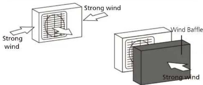
If the unit is exposed to heavy wind:
Install unit so that air outlet fan is at a 90° angle to the direction of the wind. If needed, build a barrier in front of the unit to protect it from extremely heavy winds. See Figures below.
If the unit is frequently exposed to heavy rain or snow:
Build a shelter above the unit to protect it from the rain or snow. Be careful not to obstruct air flow around the unit.
If the unit is frequently exposed to salty air (seaside):
Use outdoor unit that is specially designed to resist corrosion.
Step 2: Install drain joint(Heat pump unit only)
Before bolting the outdoor unit in place, you must install the drain joint at the bottom of the unit. Note that there are two different types of drain joints depending on the type of outdoor unit.
If the drain joint comes with a rubber seal
(see Fig. A), do the following:
- Fit the rubber seal on the end of the drain joint that will connect to the outdoor unit.
- Insert the drain joint into the hole in the base pan of the unit.
- Rotate the drain joint 90° until it clicks in place facing the front of the unit.
- Connect a drain hose extension (not included) to the drain joint to redirect water from the unit during heating mode.
If the drain joint doesn't come with a rubber seal (see Fig. B), do the following:
-
Insert the drain joint into the hole in the base pan of the unit. The drain joint will click in place.
-
Connect a drain hose extension (not included) to the drain joint to redirect water from the unit during heating mode.
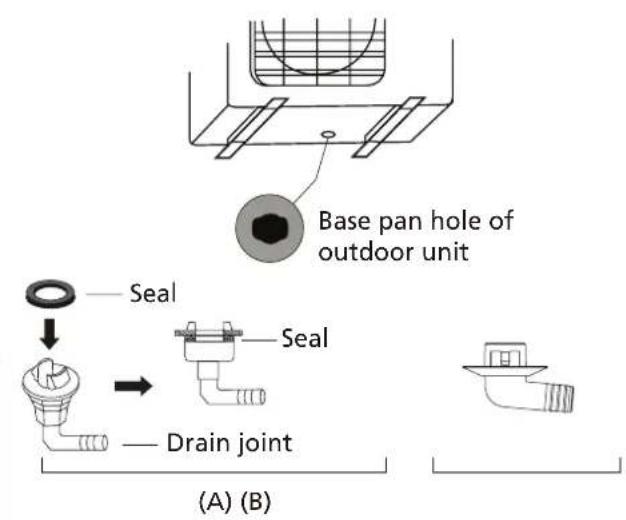

IN COLD CLIMATES
In cold climates, make sure that the drain hose is as vertical as possible to ensure swift water drainage. If water drains too slowly, it can freeze in the hose and flood the unit.
Step 3: Anchor outdoor unit
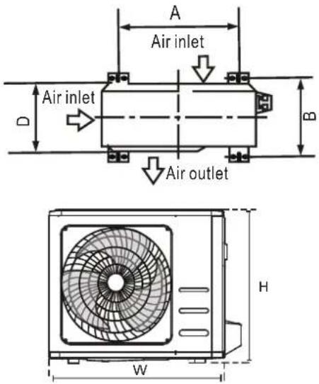
The outdoor unit can be anchored to the ground or to a wall-mounted bracket with bolt(M10). Prepare the installation base of the unit according to the dimensions below.
UNIT MOUNTING DIMENSIONS
The following is a list of different outdoor unit sizes and the distance between their mounting feet. Prepare the installation base of the unit according to the dimensions below.
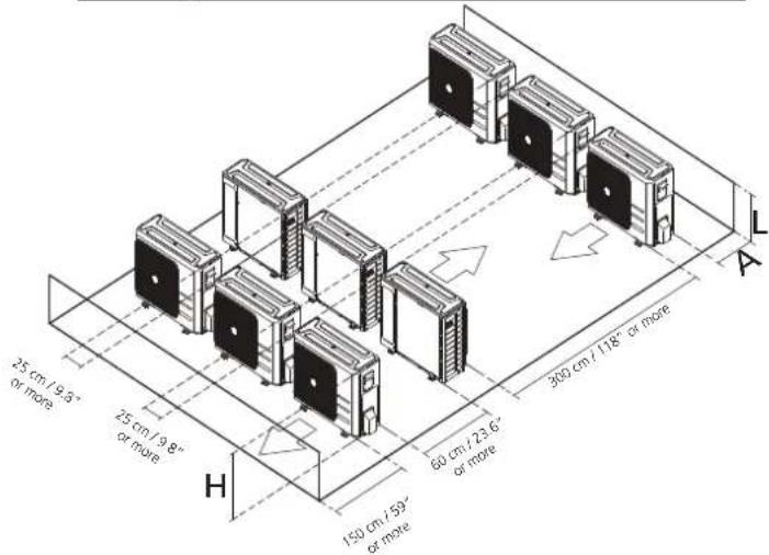
Rows of series installation The relations between H, A and L are as follows.
| L | A | |
| L ≤ H | L ≤ 1/2H | 25 cm / 9.8" or more |
| 1/2H < L ≤ H | 30 cm / 11.8" or more | |
| L >H | Can not be installed | |
| Outdoor Unit Dimensions (mm)W x H x D | Mounting DimensionsDistance A (mm) Distance B (mm) | |
| 681x434x285 (26.8"x 17.1"x 11.2") 460 (18.1") | 292 (11.5") | |
| 700x550x270 (27.5"x 21.6"x 10.6") 450 (17.7") | 260 (10.2") | |
| 700x550x275 (27.5"x 21.6"x 10.8") | 450 (17.7") | 260 (10.2") |
| 720x495x270 (28.3"x 19.5"x 10.6") | 452 (17.8") | 255 (10.0") |
| 728x555x300 (28.7"x 21.8"x 11.8") | 452 (17.8") | 302(11.9") |
| 765x555x303 (30.1"x 21.8"x 11.9") | 452 (17.8") | 286(11.3") |
| 770x555x300 (30.3"x 21.8"x 11.8") | 487 (19.2") | 298 (11.7") |
| 805x554x330 (31.7"x 21.8"x 12.9") | 511 (20.1") | 317 (12.5") |
| 800x554x333 (31.5"x 21.8"x 13.1") | 514 (20.2") | 340 (13.4") |
| 845x702x363 (33.3"x 27.6"x 14.3") | 540 (21.3") | 350 (13.8") |
| 890x673x342 (35.0"x 26.5"x 13.5") | 663 (26.1") | 354 (13.9") |
| 946x810x420 (37.2"x 31.9"x 16.5") | 673 (26.5") | 403 (15.9") |
| 946x810x410 (37.2"x 31.9"x 16.1") | 673 (26.5") | 403 (15.9") |
If you will install the unit on the ground or on a concrete mounting platform, do the following:
- Mark the positions for four expansion bolts based on dimensions chart.
- Pre-drill holes for expansion bolts.
- Place a nut on the end of each expansion bolt.
- Hammer expansion bolts into the pre-drilled holes.
- Remove the nuts from expansion bolts, and place outdoor unit on bolts.
- Put washer on each expansion bolt, then replace the nuts.
- Using a wrench, tighten each nut until snug.

WARNING
WHEN DRILLING INTO CONCRETE, EYE PROTECTION IS RECOMMENDED AT ALL TIMES.
If you will install the unit on a wall-mounted bracket, do the following:

CAUTION
Make sure that the wall is made of solid brick, concrete, or of similarly strong material. The wall must be able to support at least four times the weight of the unit.
- Mark the position of bracket holes based on dimensions chart.
- Pre-drill the holes for the expansion bolts.
- Place a washer and nut on the end of each expansion bolt.
- Thread expansion bolts through holes in mounting brackets, put mounting brackets in position, and hammer expansion bolts into the wall.
- Check that the mounting brackets are level.
- Carefully lift unit and place its mounting feet on brackets.
- Bolt the unit firmly to the brackets.
- If allowed, install the unit with rubber gaskets to reduce vibrations and noise.
Step 4: Connect signal and power cables
The outside unit's terminal block is protected by an electrical wiring cover on the side of the unit. A comprehensive wiring diagram is printed on the inside of the wiring cover.

WARNING
BEFORE PERFORMING ANY ELECTRICAL OR WIRING WORK, TURN OFF THE MAIN POWER TO THE SYSTEM.
- Prepare the cable for connection:
USE THE RIGHT CABLE
- Indoor Power Cable (if applicable): H05VV-F or H05V2V2-F
• Outdoor Power Cable: H07RN-F
• Signal Cable: H07RN-F
CHOOSE THE RIGHT CABLE SIZE
The size of the power supply cable, signal cable, fuse, and switch needed is determined by the maximum current of the unit. The maximum current is indicated on the nameplate located on the side panel of the unit. Refer to this nameplate to choose the right cable, fuse, or switch.
a. Using wire strippers, strip the rubber jacket from both ends of cable to reveal about 40mm (1.57in) of the wires inside.
b. Strip the insulation from the ends of the wires.
c. Using a wire crimper, crimp u-lugs on the ends of the wires.
PAY ATTENTION TO LIVE WIRE
While crimping wires, make sure you clearly distinguish the Live ("L") Wire from other wires.

WARNING
ALL WIRING WORK MUST BE PERFORMED STRICTLY IN ACCORDANCE WITH THE WIRING DIAGRAM LOCATED INSIDE OF WIRE COVER OF THE OUTDOOR UNIT.
- Unscrew the electrical wiring cover and remove it.
- Unscrew the cable clamp below the terminal block and place it to the side.
- Connect the wire according to the wiring diagram, and firmly screw the u-lug of each wire to its corresponding terminal.
- After checking to make sure every connection is secure, loop the wires around to prevent rain water from flowing into the terminal.
- Using the cable clamp, fasten the cable to the unit. Screw the cable clamp down tightly.
- Insulate unused wires with PVC electrical tape. Arrange them so that they do not touch any electrical or metal parts.
- Replace the wire cover on the side of the unit, and screw it in place.
In North America
- Remove the wire cover from the unit by loosening the 3 screws.
- Dismount caps on the conduit panel.
- Temporarily mount the conduit tubes (not included) on the conduit panel.
- Properly connect both the power supply and low voltage lines to the corresponding terminals on the terminal block.
- Ground the unit in accordance with local codes.
- Be sure to size each wire allowing several inches longer than the required length for wiring.
- Use lock nuts to secure the conduit tubes.
Please select the appropriate through-hole according to the diameter of the wire.
Refrigerant Piping Connection
When connecting refrigerant piping, do not let substances or gases other than the specified refrigerant enter the unit. The presence of other gases or substances will lower the unit's capacity, and can cause abnormally high pressure in the refrigeration cycle. This can cause explosion and injury.
Note on Pipe Length
The length of refrigerant piping will affect the performance and energy efficiency of the unit. Nominal efficiency is tested on units with a pipe length of 5 meters (16.5ft)( In North America, the standard pipe length is 7.5m (25'). A minimum pipe run of 3 metres is required to minimise vibration & excessive noise. In special tropical area, for the R290 refrigerant models, no refrigerant can be added and the maximum length of refrigerant pipe should not exceed 10 meters(32.8ft).
Refer to the table below for specifications on the maximum length and drop height of piping.
Maximum Length and Drop Height of Refrigerant Piping per Unit Model
| Model Capacity (BTU/h) Max. Length (m) Max. Drop Height (m) | |||
| R410A,R32 Inverter Split Air Conditioner | < 15,000 | 25 (82ft) 10 (33ft) | |
| ≥ 15,000 and < 24,000 30 (98.5ft) 20 (66ft) | |||
| ≥ 24,000 and < 36,000 50 (164ft) 25 (82ft) | |||
| R22 Fixed-speed Split Air Conditioner | < 18,000 | 10 (33ft) 5 (16ft) | |
| ≥ 18,000 and < 21,000 | 15 (49ft) | 8(26ft) | |
| ≥ 21,000 and < 35,000 10(33ft) 20 (66ft) | |||
| R410A, R32 Fixed-speed Split Air Conditioner | 20 (66ft) | 8(26ft)< 18,000 | |
| ≥ 18,000 and < 36,000 | 25 (82ft) | 10(33ft) | |
Connection Instructions – Refrigerant Piping
Step 1: Cut pipes
When preparing refrigerant pipes, take extra care to cut and flare them properly. This will ensure efficient operation and minimize the need for future maintenance.
- Measure the distance between the indoor and outdoor units.
- Using a pipe cutter, cut the pipe a little longer than the measured distance.
- Make sure that the pipe is cut at a perfect 90^ angle.

DO NOT DEFORM PIPE WHILE CUTTING
Be extra careful not to damage, dent, or deform the pipe while cutting. This will drastically reduce the heating efficiency of the unit.
Step 2: Remove burrs
Burrs can affect the air-tight seal of refrigerant piping connection. They must be completely removed.
- Hold the pipe at a downward angle to prevent burrs from falling into the pipe.
- Using a reamer or deburring tool, remove all burrs from the cut section of the pipe.
Step 3: Flare pipe ends
Proper flaring is essential to achieve an airtight seal.
- After removing burrs from cut pipe, seal the ends with PVC tape to prevent foreign materials from entering the pipe.
- Sheath the pipe with insulating material.
- Place flare nuts on both ends of pipe. Make sure they are facing in the right direction, because you can't put them on or change their direction after flaring.
- Remove PVC tape from ends of pipe when ready to perform flaring work.
- Clamp flare form on the end of the pipe. The end of the pipe must extend beyond the edge of the flare form in accordance with the dimensions shown in the table below.
natural_image
Illustration of a hand gripping a tool with multiple circular components, no text or symbols present.PIPING EXTENSION BEYOND FLARE FORM
| Outer Diameter of Pipe (mm) | A (mm) | |
| Min. Max. | ||
| ∅ 6.35 (∅ 0.25") | 0.7 (0.0275") | 1.3 (0.05") |
| ∅ 9.52 (∅ 0.375") | 1.0 (0.04") | 1.6 (0.063") |
| ∅12.7 (∅ 0.5") 1.0 | (0.04") 1.8 (0.07") | |
| ∅ 16 (∅ 0.63") | 2.0 (0.078") | 2.2 (0.086") |
| ∅ 19 (∅ 0.75") | 2.0 (0.078") | 2.4 (0.094") |
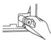
- Place flaring tool onto the form.
- Turn the handle of the flaring tool clockwise until the pipe is fully flared.
- Remove the flaring tool and flare form, then inspect the end of the pipe for cracks and even flaring.
Step 4: Connect pipes
When connecting refrigerant pipes, be careful not to use excessive torque or to deform the piping in any way. You should first connect the low-pressure pipe, then the high-pressure pipe.
MINIMUM BEND RADIUS
When bending connective refrigerant piping, the minimum bending radius is 10cm.
Instructions for Connecting Piping to Indoor Unit
- Align the center of the two pipes that you will connect.
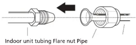
-
Tighten the flare nut as tightly as possible by hand.
-
Using a spanner, grip the nut on the unit tubing.
-
While firmly gripping the nut on the unit tubing, use a torque wrench to tighten the flare nut according to the torque values in the Torque Requirements table below. Loosen the flaring nut slightly, then tighten again.
natural_image
Illustration of a hand using a tool to lift a mechanical component (no text or symbols)TORQUE REQUIREMENTS
| Outer Diameter of Pipe (mm) | Tightening Torque (N•m) | Flare dimension(B) (mm) | Flare shape |
| ∅ 6.35 (∅ 0.25") | 18~20(180~200kgf.cm) | 8.4~8.7 (0.33~0.34") | 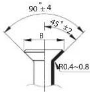 |
| ∅ 9.52 (∅ 0.375") | 32~39(320~390kgf.cm) | 13.2~13.5 (0.52~0.53") | |
| ∅ 12.7 (∅ 0.5") | 49~59(490~590kgf.cm) | 16.2~16.5 (0.64~0.65") | |
| ∅ 16 (∅ 0.63") | 57~71(570~710kgf.cm) | 19.2~19.7 (0.76~0.78") | |
| ∅ 19 (∅ 0.75") | 67~101(670~1010kgf.cm) | 23.2~23.7 (0.91~0.93") |

DO NOT USE EXCESSIVE TORQUE
Excessive force can break the nut or damage the refrigerant piping. You must not exceed torque requirements shown in the table above.
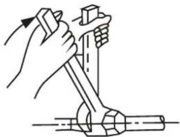
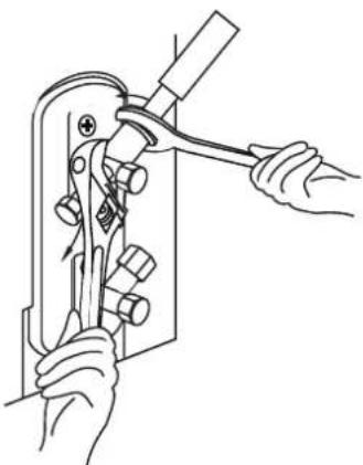
Instructions for Connecting Piping to Outdoor Unit
-
Unscrew the cover from the packed valve on the side of the outdoor unit.
-
Remove protective caps from ends of valves.
-
Align flared pipe end with each valve, and tighten the flare nut as tightly as possible by hand.
-
Using a spanner, grip the body of the valve. Do not grip the nut that seals the service valve.
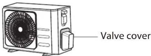
-
While firmly gripping the body of the valve, use a torque wrench to tighten the flare nut according to the correct torque values.
-
Loosen the flaring nut slightly, then tighten again.
-
Repeat Steps 3 to 6 for the remaining pipe.

USE SPANNER TO GRIP MAIN BODY OF VALVE
Torque from tightening the flare nut can snap off other parts of valve.
natural_image
Line drawing of hands using a tool to handle a mechanical component (no text or symbols present)
CAUTION
- Oil traps
If the indoor unit is installed higher than the outdoor unit:
-If oil flows back into the outdoor unit's compressor, this might cause liquid compression or deterioration of oil return.
Oil traps in the rising gas piping can prevent this.
An oil trap should be installed every 10m (32.8ft) of vertical suction line riser.

CAUTION
If the outdoor unit is installed higher than the indoor unit:
-It is recommended that vertical suction risers not be upsized. Proper oil return to the compressor should be maintained with suction gas velocity. If velocities drop below 7.62m/s (1500fpm (feet per minute)), oil return will be decreased. An oil trap should be installed every 6m(20ft) of vertical suction line riser.
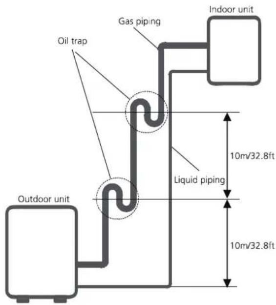
The indoor unit is installed higher than the outdoor unit
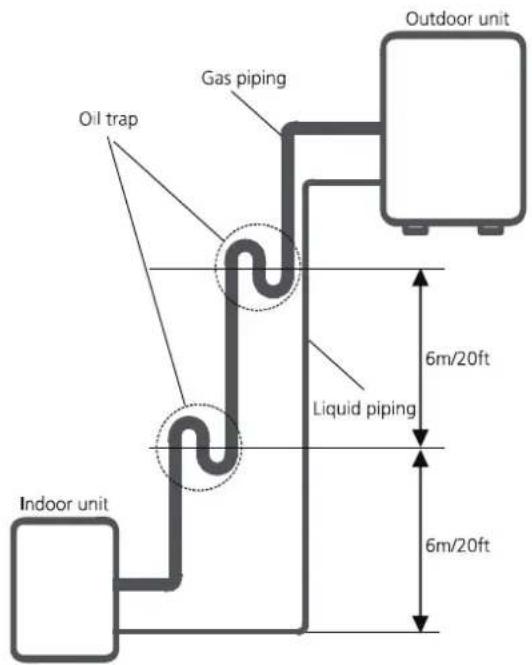
The outdoor unit is installed higher than the indoor unit
Air Evacuation
Preparations and Precautions
Air and foreign matter in the refrigerant circuit can cause abnormal rises in pressure, which can damage the air conditioner, reduce its efficiency, and cause injury. Use a vacuum pump and manifold gauge to evacuate the refrigerant circuit, removing any non-condensable gas and moisture from the system.
Evacuation should be performed upon initial installation and when unit is relocated.
BEFORE PERFORMING EVACUATION
√ Check to make sure the connective pipes between the indoor and outdoor units are connected properly.
√ Check to make sure all wiring is connected properly.
Evacuation Instructions
- Connect the charge hose of the manifold gauge to service port on the outdoor unit's low pressure valve.
- Connect another charge hose from the manifold gauge to the vacuum pump.
- Open the Low Pressure side of the manifold gauge. Keep the High Pressure side closed.
- Turn on the vacuum pump to evacuate the system.
- Run the vacuum for at least 15 minutes, or until the Compound Meter reads -76cmHG (-10 ^5 Pa).
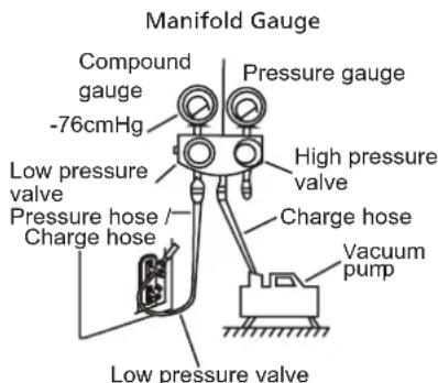
- Close the Low Pressure side of the manifold gauge, and turn off the vacuum pump.
-
Wait for 5 minutes, then check that there has been no change in system pressure.
-
If there is a change in system pressure, refer to Gas Leak Check section for information on how to check for leaks. If there is no change in system pressure, unscrew the cap
- from the packed valve (high pressure valve). Insert hexagonal wrench into the packed valve (high pressure valve) and open the valve by turning the wrench in a 1/4 counterclockwise turn. Listen for gas to exit the system, then close the valve after 5 seconds.
- Watch the Pressure Gauge for one minute to make sure that there is no change in pressure. The Pressure Gauge should read slightly higher than atmospheric pressure.
- Remove the charge hose from the service port.
-
Using hexagonal wrench, fully open both the high pressure and low pressure valves.
-
Tighten valve caps on all three valves (service port, high pressure, low pressure) by hand. You may tighten it further using a torque wrench if needed.
! OPEN VALVE STEMS GENTLY
When opening valve stems, turn the hexagonal wrench until it hits against the stopper. Do not try to force the valve to open further.
Note on Adding Refrigerant
Some systems require additional charging depending on pipe lengths. The standard pipe length varies according to local regulations. For example, in North America, the standard pipe length is 7.5m (25'). In other areas, the standard pipe length is 5m (16'). The refrigerant should be charged from the service port on the outdoor unit's low pressure valve. The additional refrigerant to be charged can be calculated using the following formula:
ADDITIONAL REFRIGERANT PER PIPE LENGTH
| Connective Pipe Length (m) | Air Purging Method | Additional Refrigerant | |
| ≤ Standard pipe length | Vacuum Pump N/A | ||
| > Standard pipe length | Vacuum Pump | Liquid Side: ∅ 6.35 (∅ 0.25")R32:(Pipe length – standard length) x 12g/m(Pipe length – standard length) x 0.13oZ/ftR290:(Pipe length – standard length) x 10g/m(Pipe length – standard length) x 0.10oZ/ftR410A:(Pipe length – standard length) x 15g/m(Pipe length – standard length) x 0.16oZ/ftR22:(Pipe length – standard length) x 20g/m(Pipe length – standard length) x 0.21oZ/ft | Liquid Side: ∅ 9.52 (∅ 0.375")R32:(Pipe length – standard length) x 24g/m(Pipe length – standard length) x 0.26oZ/ftR290:(Pipe length – standard length) x 18g/m(Pipe length – standard length) x 0.19oZ/ftR410A:(Pipe length – standard length) x 30g/m(Pipe length – standard length) x 0.32oZ/ftR22:(Pipe length – standard length) x 40g/m(Pipe length – standard length) x 0.42oZ/ft |
For R290 refrigerant unit, the total amount of refrigerant to be charged is no more than: 387g(<=9000Btu/h), 447g(>9000Btu/h and <=12000Btu/h), 547g(>12000Btu/h and <=18000Btu/h), 632g(>18000Btu/h and <=24000Btu/h).

CAUTION DO NOT mix refrigerant types.
Electrical and Gas Leak Checks
Before Test Run
Only perform test run after you have completed the following steps:
- Electrical Safety Checks – Confirm that the unit's electrical system is safe and operating properly
- Gas Leak Checks – Check all flare nut connections and confirm that the system is not leaking
- Confirm that gas and liquid (high and low pressure) valves are fully open
Electrical Safety Checks
After installation, confirm that all electrical wiring is installed in accordance with local and national regulations, and according to the Installation Manual.
BEFORE TEST RUN
Check Grounding Work
Measure grounding resistance by visual detection and with grounding resistance tester. Grounding resistance must be less than 0.1 .
Note: This may not be required for some locations in the US.
DURING TEST RUN
Check for Electrical Leakage
During the Test Run, use an electroprobe and multimeter to perform a comprehensive electrical leakage test.
If electrical leakage is detected, turn off the unit immediately and call a licensed electrician to find and resolve the cause of the leakage.
Note: This may not be required for some locations in the US.

WARNING – RISK OF ELECTRIC SHOCK
ALL WIRING MUST COMPLY WITH LOCAL AND NATIONAL ELECTRICAL CODES, AND MUST BE INSTALLED BY A LICENSED ELECTRICIAN.
Gas Leak Checks
There are two different methods to check for gas leaks.
Soap and Water Method
Using a soft brush, apply soapy water or liquid detergent to all pipe connection points on the indoor unit and outdoor unit. The presence of bubbles indicates a leak.
Leak Detector Method
If using leak detector, refer to the device's operation manual for proper usage instructions.
AFTER PERFORMING GAS LEAK CHECKS
After confirming that the all pipe connection points DO NOT leak, replace the valve cover on the outside unit.
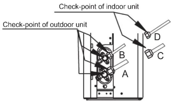
A: Low pressure stop valve
B: High pressure stop valve
C& D: Indoor unit flare nuts
Test Run
Test Run Instructions
You should perform the Test Run for at least 30 minutes.
- Connect power to the unit.
- Press the ON/OFF button on the remote controller to turn it on.
- Press the MODE button to scroll through the following functions, one at a time:
• COOL – Select lowest possible temperature
• HEAT – Select highest possible temperature
- Let each function run for 5 minutes, and perform the following checks:
| List of Checks to Perform PASS/FAIL | ||
| No electrical leakage | ||
| Unit is properly grounded | ||
| All electrical terminals properly covered | ||
| Indoor and outdoor units are solidly installed | ||
| All pipe connection points do not leak | Outdoor (2): | Indoor (2): |
| Water drains properly from drain hose | ||
| All piping is properly insulated | ||
| Unit performs COOL function properly | ||
| Unit performs HEAT function properly | ||
| Indoor unit louvers rotate properly | ||
| Indoor unit responds to remote controller | ||
DOUBLE-CHECK PIPE CONNECTIONS
During operation, the pressure of the refrigerant circuit will increase. This may reveal leaks that were not present during your initial leak check. Take time during the Test Run to double-check that all refrigerant pipe connection points do not have leaks. Refer to Gas Leak Check section for instructions.
- After the Test Run is successfully completed, and you confirm that all checks points in List of Checks to Perform have PASSED, do the following:
a. Using remote control, return unit to normal operating temperature.
b. Using insulation tape, wrap the indoor refrigerant pipe connections that you left uncovered during the indoor unit installation process.
IF AMBIENT TEMPERATURE IS BELOW 17°C (62°F)
You can't use the remote controller to turn on the COOL function when the ambient temperature is below 17°C. In this instance, you can use the MANUAL CONTROL button to test the COOL function.
- The MANUAL CONTROL button is located on the right-hand side panel of the unit.
- Press the button 2 times to select the COOL function.
- Perform Test Run as normal.
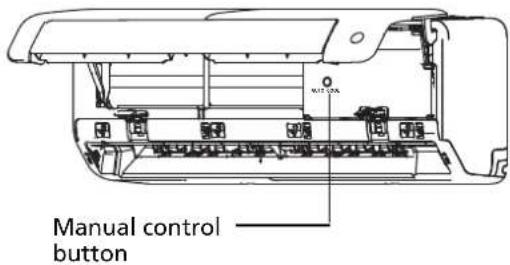
Product Information Sheet
Delegated Regulation (EU) 626/2011
Supplier name or trademark Midea
Model identifier MSEPBU-09HRFN8-set
Indoor Model Identifier(s) MSEPBU-09HRFN8
Outdoor Model Identifier MOX330-09HFN8
Inside sound power levels (Cooling mode) 58 dB
Inside sound power levels (Heating mode)
Outside sound power levels (Cooling mode) 64 dB
Outside sound power levels (Heating mode) - dB
Refrigerant Name R32
Refrigerant GWP 675
Refrigerant leakage contributes to climate change. Refrigerant with lower global warming potential (GWP) would contribute less to global warming than a refrigerant with higher GWP, if leaked to the atmosphere. This appliance contains a refrigerant fluid with a GWP equal to 675. This means that if 1 kg of this refrigerant fluid would be leaked to the atmosphere, the impact on global warming would be 675 times higher than 1 kg of CO 2, over a period of 100 years. Never try to interfere with the refrigerant circuit yourself or disassemble the product yourself and always ask a professional.
Cooling Mode
Seasonal Energy Efficiency Ratio (SEER) 8.6
Energy Efficiency Class A+++
Annual Electricity Consumption Energy consumption 106 kWh per year, based on
standard test results. Actual energy consumption will depend on how the appliance is used and where it is located.
Design Load 2.6 kW
Heating Mode
Seasonal Coefficient Of Performance (SCOP) 4.6
(Average season)
Energy Efficiency Class (Average season) A++
Annual Electricity Consumption (Average season) Energy consumption 730 kWh per year, based on standard test results. Actual energy consumption will depend on how the appliance is used and where it is located.
Seasonal Coefficient Of Performance (SCOP) (Warmer season)
Seasonal Coefficient Of Performance (SCOP) (Colder season)
Energy Efficiency Class (Warmer season)
Energy Efficiency Class (Colder season)
Annual Electricity Consumption (Warmer season)
Annual Electricity Consumption (Colder season)
Design Load (Average season) 2.4 kW
Design Load (Warmer season)
Design Load (Colder season)
Declared capacity (Average season) 1.9 kW
Declared capacity (Warmer season)
Declared capacity (Colder season)
Backup heating capacity (Average season) 0.5 kW
Backup heating capacity (Warmer season)
Backup heating capacity (Colder season)
Product Information Sheet
Delegated Regulation (EU) 626/2011
Supplier name or trademark Midea
Model identifier MSEPBU-12HRFN8-set
Indoor Model Identifier(s) MSEPBU-12HRFN8
Outdoor Model Identifier MOX330-12HFN8
Inside sound power levels (Cooling mode) 59 dB
Inside sound power levels (Heating mode)
Outside sound power levels (Cooling mode) 65 dB
Outside sound power levels (Heating mode) - dB
Refrigerant Name R32
Refrigerant GWP 675
Refrigerant leakage contributes to climate change. Refrigerant with lower global warming potential (GWP) would contribute less to global warming than a refrigerant with higher GWP, if leaked to the atmosphere. This appliance contains a refrigerant fluid with a GWP equal to 675. This means that if 1 kg of this refrigerant fluid would be leaked to the atmosphere, the impact on global warming would be 675 times higher than 1 kg of CO 2, over a period of 100 years. Never try to interfere with the refrigerant circuit yourself or disassemble the product yourself and always ask a professional.
Cooling Mode
Seasonal Energy Efficiency Ratio (SEER) 8.5
Energy Efficiency Class A+++
Annual Electricity Consumption Energy consumption 144 kWh per year, based on
standard test results. Actual energy consumption will depend on how the appliance is used and where it is located.
Design Load 3.5 kW
Heating Mode
Seasonal Coefficient Of Performance (SCOP) 4.6
(Average season)
Energy Efficiency Class (Average season) A++
Annual Electricity Consumption (Average season) Energy consumption 730 kWh per year, based on standard test results. Actual energy consumption will depend on how the appliance is used and where it is located.
Seasonal Coefficient Of Performance (SCOP) (Warmer season)
Seasonal Coefficient Of Performance (SCOP) (Colder season)
Energy Efficiency Class (Warmer season)
Energy Efficiency Class (Colder season)
Annual Electricity Consumption (Warmer season)
Annual Electricity Consumption (Colder season)
Design Load (Average season) 2.4 kW
Design Load (Warmer season)
Design Load (Colder season)
Declared capacity (Average season) 1.9 kW
Declared capacity (Warmer season)
Declared capacity (Colder season)
Backup heating capacity (Average season) 0.5 kW
Backup heating capacity (Warmer season)
Backup heating capacity (Colder season)
Midea
make yourself at home
Split Air Conditioner ALL EASY PRO
USER MANUAL
POWER SOURCE: 220-240V\~50Hz,1ph RATED INPUT: 2300W

natural_image
Line drawing of a rectangular electronic device with a handle and mounting bracket (no text or symbols)Read this manual carefully before installing or operating your new air conditioning unit. Make sure to save this manual for future reference.
Inhaltsverzeichnis
natural_image
Diagram of a water spray device on a solar panel array with a faucet (no text or symbols)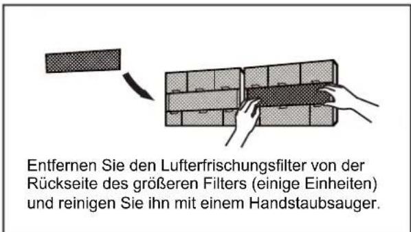
natural_image
Diagram of a 3x3 grid structure with a triangular pointer and label 'H' (no text or symbols within the grid)natural_image
Simple line drawing of a house with wavy lines inside, no text or symbols presentnatural_image
Simple line drawing of a remote control with a handle and internal components (no text or symbols)natural_image
3D grid diagram with shaded cells and a small arrow pointing to the top-right corner (no text or symbols)Lecks ausschließen
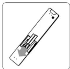
natural_image
Diagram of a remote control device with a gray arrow indicating a location or movement (no text or symbols present)natural_image
Pure technical diagram of a mechanical assembly with no text, numbers, or symbolsnatural_image
Mechanical diagram showing a tool interacting with a bolt and pipe fitting (no text or symbols)Rohre anschließen
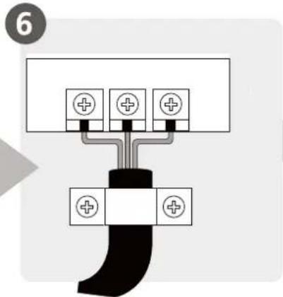
natural_image
Illustration of hands holding a black object over a wavy line (no text or symbols)natural_image
Diagram of a cable assembly with coiled and twisted wires, no text or symbols presentnatural_image
Illustration of two hands holding a rectangular object with horizontal lines and upward arrows, no text or symbols present(1)
Einheit: mm(inch)
natural_image
Technical line drawing of two air conditioner unit designs with coiled tubing (no text or symbols)natural_image
Pure mechanical diagram showing a bracket and vertical wall with a checkmark (no text or symbols)KORREKT
natural_image
Simple line drawing of a mechanical joint or bracket with a cross symbol (no text or labels)FALSCH
natural_image
Simple line drawing of a mechanical or electrical component with no text or symbolsFALSCH
natural_image
Simple line drawing of a door and pipe assembly with a cross symbol (no text or labels)FALSCH
natural_image
Technical line drawing of a mechanical device showing internal components and housing (no text or symbols)natural_image
Technical line drawing of a front-mounted air conditioner fan with labeled dimensions H and W (no text or symbols beyond labels)natural_image
Simple line drawing of a mechanical lever or clamp device (no text or symbols)natural_image
Technical illustration of a mechanical component with two views showing internal structure (no text or symbols)natural_image
Illustration of hands using a tool to lift a mechanical component (no text or symbols)natural_image
Line drawing of a portable air conditioner unit with fan and control panel (no text or symbols)Ventildeckel
natural_image
Line drawing of hands using a tool to adjust or install a mechanical component (no text or symbols present)
VORSICHT
make yourself at home
Split Air Conditioner ALL EASY PRO
USER MANUAL
POWER SOURCE: 220-240V\~50Hz,1ph RATED INPUT: 2300W

natural_image
Line drawing of a rectangular electronic device with a handle and mounting bracket (no text or symbols)Read this manual carefully before installing or operating your new air conditioning unit. Make sure to save this manual for future reference.
Inhoudsopgave
Veiligheidsmaatregelen....04
Handleiding
WAARSCHUWINGEN VOOR PRODUCTINSTALLATIE
natural_image
Diagram of a solar panel with a faucet and a star-shaped object on its surface (no text or symbols)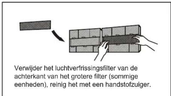
natural_image
Diagram of a 3D grid structure with a small arrow pointing to the top-right corner (no text or symbols)Reinig alle filters
natural_image
Simple line drawing of a house with wavy lines inside, enclosed in a rounded square frame (no text or symbols)natural_image
Simple line drawing of a remote control with a handle and scroll (no text or symbols)natural_image
Symbol of a crossed-out electrical hazard zone with lightning bolts (no text or labels)natural_image
Simple 3D grid diagram with shaded cells and a small arrow pointing to the top-right corner (no text or symbols)Reinig alle filters
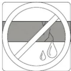
natural_image
Diagram of a remote control with a gray arrow indicating left-side motion (no text or symbols)Vervang de batterijen
natural_image
Mechanical diagram showing a tool interacting with a bolt and nut (no text or symbols present)Sluit leidingen aan
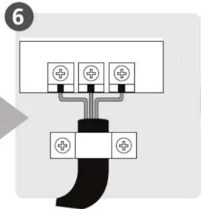
natural_image
Illustration of two hands holding a black object over a textured surface, no text or symbols presentnatural_image
Diagram of a cable assembly with coiled and twisted wires, no text or symbols presentnatural_image
Illustration of two hands holding a rectangular object with horizontal lines and upward arrows, no text or symbols present.Monteer de binnen-unit
Eenheidsonderdelen
(1)
Eenheid: mm (inch)
natural_image
Technical line drawing of two identical air conditioner unit designs with coiled tubing (no text or symbols)OPMERKING OVER HET AANSLUITEN VAN LEIDINGEN
natural_image
Technical line drawing of a mechanical assembly with an inset close-up showing internal components (no text or symbols)OPMERKING OVER AFVOERSLANG PLAATSING
natural_image
Simple line drawing of a mechanical joint or bracket with a checkmark (no text or symbols)CORRECT
natural_image
Pure mechanical diagram showing a bracket and vertical wall with a cross symbol (no text or labels)ONJUIST
natural_image
Simple line drawing of a wall-mounted device with a switch and a separate X symbol (no text or labels)ONJUIST
natural_image
Simple line drawing of a toilet with a wall and pipe, no text or symbols presentONJUIST
natural_image
Technical line drawing of a mechanical device showing internal components and assembly (no text or symbols)natural_image
Technical line drawing of a front-end air conditioner unit with labeled dimensions H and W (no text or symbols beyond labels)| Afmetingen buitenunit (mm)W × H × D | Montage afmetingen | ||
| Afstand A (mm) | Afstand B (mm) | ||
| 681 × 434 × 285 (26,8 "× 17,1" × 11,2 ") 460 (18,1 ") 292 (11,5") | |||
| 700 × 550 × 270 (27,5 "× 21,6" × 10,6 ") 450 (17,7 ") 260 (10,2") | |||
| 700 × 550 × 275 (27,5 "× 21,6" × 10,8 ") 450 (17,7 ") 260 (10,2") | |||
| 720 × 495 × 270 (28,3 "× 19,5" × 10,6 ") 452 (17,8 ") 255 (10,0") | |||
| 728 × 555 × 300 (28,7 "× 21,8" × 11,8 ") 452 (17,8 ") 302 (11,9") | |||
| 765 × 555 × 303 (30,1 "× 21,8" × 11,9 ") 452 (17,8 ") 286 (11,3") | |||
| 770 × 555 × 300 (30,3 "× 21,8" × 11,8 ") 487 (19,2 ") 298 (11,7") | |||
| 805 × 554 × 330 (31,7 "× 21,8" × 12,9 ") 511 (20,1 ") 317 (12,5") | |||
| 800 × 554 × 333 (31,5 "× 21,8" × 13,1 ") 514 (20,2 ") 340 (13,4") | |||
| 845 × 702 × 363 (33,3 "× 27,6" × 14,3 ") 540 (21,3 ") 350 (13,8") | |||
| 890 × 673 × 342 (35,0 "× 26,5" × 13,5 ") 663 (26,1 ") 354 (13,9") | |||
| 946 × 810 × 420 (37,2 "× 31,9" × 16,5 ") 673 (26,5 ") 403 (15,9") | |||
| 946 × 810 × 410 (37,2 "× 31,9" × 16,1 ") 673 (26,5 ") 403 (15,9") | |||
natural_image
Illustration of a mechanical lever assembly with two plates and a central handle (no text or symbols)LEIDINGSVERLENGING BUITEN FLARE-VORM
| Buitendiameter van pijp (mm) | A (mm) | |
| Min. Max. | ||
| 6,35 ( 0,25 ") 0.7 | (0,0275 ") 1.3 (0,05 ") | |
| 9,52 ( 0,375 ") 1,0 | (0,04 ") 1.6 (0,063 ") | |
| 12,7 ( 0,5 ") 1.0 | (0,04 ") 1.8 (0,07 ") | |
| 16 ( 0,63 ") 2,0 | (0,078 ") 2,2 (0,086 ") | |
| 19 ( 0,75 ") 2.0 | (0,078 ") 2,4 (0,094 ") | |
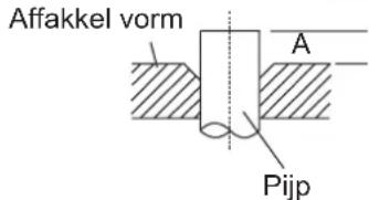
natural_image
Diagram showing two mechanical components with a directional arrow indicating movement or assembly (no text or symbols present)Binnen-unit buizen Affakkel moer Pijp
natural_image
Line drawing of a hand using a tool to lift a mechanical component (no text or symbols)KOPPELVEREISTEN
| Buitendiameter van pijp (mm) | Aanhaalmoment (N • m) | Affakkel-afmeting (B) (mm) | Affakkel vorm |
| ø6,35 (ø0,25 ") 18 ~ | 20 (180 ~ 200kgf.cm) 8,4 ~ 8,7 (0,33 ~ 0,34 ") | 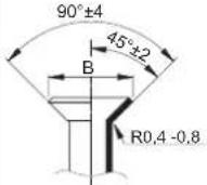 | |
| ø9,52 (ø0,375 ") 32 ~ | 39 (320 ~ 390kgf.cm) 13,2 ~ 13,5 | (0,52 ~ 0,53 ") | |
| ø12,7 (ø0,5 ") 49 ~ 59 | (490 ~ 590kgf.cm) 16,2 ~ 16,5 | (0,64 ~ 0,65 ") | |
| ø16 (ø0,63 ") 57 ~ 71 | (570 ~ 710kgf.cm) 19,2 ~ 19,7 | (0,76 ~ 0,78 ") | |
| ø19 (ø0,75 ") 67 ~ 101 | (670 ~ 1010kgf.cm) 23,2 ~ 23,7 | (0,91 ~ 0,93 ") |

GEBRUIK GEEN EXCESSIEF KOPPEL
natural_image
Line drawing of hands using a tool to adjust or install a mechanical component (no text or symbols present)
VOORZICHTIGHEEID
- Olievallen
make yourself at home
Split Air Conditioner ALL EASY PRO
USER MANUAL
POWER SOURCE: 220-240V\~50Hz,1ph RATED INPUT: 2300W

natural_image
Line drawing of a rectangular electronic device with a handle and mounting bracket (no text or symbols)Read this manual carefully before installing or operating your new air conditioning unit. Make sure to save this manual for future reference.
Table des Matières
Fig. C
natural_image
Diagram of a water spray device on a solar panel array (no text or symbols)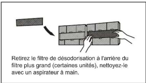
natural_image
Diagram of a 3x3 grid structure with a height dimension labeled 'h' (no text or symbols beyond the label)natural_image
Simple line drawing of a house with wavy lines inside, enclosed in a rounded square frame (no text or symbols)natural_image
Diagram of a remote control with internal components and an arrow indicating direction (no text or symbols)natural_image
Diagram of a grid-patterned rectangular structure with a small arrow pointing upward (no text or symbols)Vérifiez les fuites
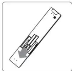
natural_image
Diagram of a remote control panel with an arrow indicating left-side motion (no text or symbols)Remplacez les batteries
natural_image
Illustration of a hand using a tool to adjust a component, with no visible text or symbols.natural_image
Mechanical diagram showing a tool interacting with a bolt and valve (no text or symbols present)Connector les tuyaux
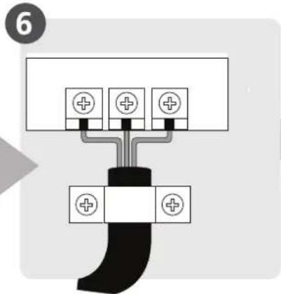
natural_image
Illustration of hands holding a black object with a ruler partially visible (no text or symbols)natural_image
Diagram showing a cable being inserted into a coiled cable, with no text or symbols present.natural_image
Illustration of two hands holding a rectangular object with horizontal lines and upward arrows, no text or symbols presentnatural_image
Technical line drawing of two air conditioner unit designs with coiled tubing (no text or symbols)NOTE SUR LE RACCORDEMENT DE LA TUYAUTERIE
natural_image
Simple line drawing of a mechanical joint or bracket with a checkmark (no text or symbols)CORRECT
natural_image
Simple line drawing of a pipe connection with a wall and a cross symbol (no text or labels)PAS CORRECT
natural_image
Simple line drawing of a wall-mounted device with a handle and base, no text or symbols presentPAS CORRECT
natural_image
Simple line drawing of a toilet and sink assembly with no text or symbolsPAS CORRECT
natural_image
Technical line drawing of a mechanical assembly with no visible text or symbolsnatural_image
Pure technical diagram showing a curved structure above a rectangular plate with diagonal braces (no text or symbols)
(A) (B)

SOUS CLIMAT FROID
natural_image
Technical line drawing of a wall-mounted air conditioner fan with labeled dimensions H and W (no text or symbols beyond labels)natural_image
Illustration of a mechanical clamp or tool with three plates and a central handle (no text or symbols)EXTENSION DE TUYAUTERIE AU-DELA DU FORME D'EVASEMENT
| Diamètre extérieurdu tuyau (mm) | A (mm) | |
| Min. Max. | ||
| 6,35 ( 0,25") 0,7 | (0,0275") 1,3 (0,05") | |
| 9,52 ( 0,375") 1,0 | (0,04") 1,6 (0,063") | |
| 12,7 ( 0,5") 1,0 | (0,04") 1,8 (0,07") | |
| 16 ( 0,63") 2,0 | (0,078") 2,2 (0,086") | |
| 19 ( 0,75") 2,0 | (0,078") 2,4 (0,094") | |
Forme d'évasement
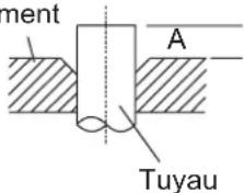
natural_image
Illustration of a hand using a tool to lift a mechanical component (no text or symbols present)EXIGENCES DE TORQUE
| Diamètre extérieur du tuyau (mm) | Couple de serrage (N.m) | Dimension d’évasement (B) (mm) | Forme d’évasement |
| 6,35 ( 0,25") 18 - 20 | (180 - 200kgf.cm) 8,4 - 8,7 (0,33 - 0,34") | 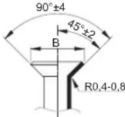 | |
| 9,52 ( 0,375") 32 - 39 | (320 - 390kgf.cm) 13,2 - 13,5 (0,52 - 0,53") | ||
| 12,7 ( 0,5") 49 - 59 | (490 - 590kgf.cm) 16,2 - 16,5 (0,64 - 0,65") | ||
| 16 ( 0,63") 57 - 71 | (570 - 710kgf.cm) 19,2 - 19,7 (0,76 - 0,78") | ||
| 19 ( 0,75") 67 - 101 | (670 - 1010kgf.cm) 23,2 - 23,7 (0,91 - 0,93") |

NE PAS UTILISER LA TORQUE EXCESSIVE
natural_image
Line drawing of a small air conditioner unit with fan and vent (no text or symbols)Couvercle de vanne
natural_image
Line drawing of hands using a tool to adjust or install a mechanical component (no text or symbols present)
ATTENTION
make yourself at home
Split Air Conditioner ALL EASY PRO
USER MANUAL
POWER SOURCE: 220-240V\~50Hz,1ph RATED INPUT: 2300W
natural_image
Line drawing of a rectangular electronic device with a handle and mounting bracket (no text or symbols)Read this manual carefully before installing or operating your new air conditioning unit. Make sure to save this manual for future reference.
Indholdsfortegnelse
natural_image
Diagram of a water spray device mounted on a grid panel with a faucet (no text or symbols)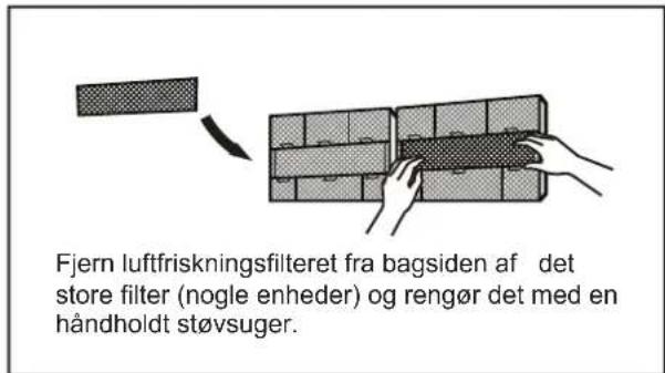
natural_image
Simple 3D grid diagram with a small arrow pointing to the top-right corner (no text or symbols)Rengør alle filtre
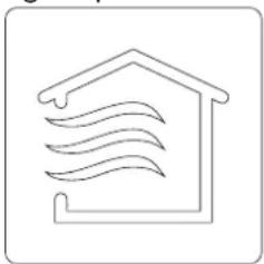
natural_image
Simple line drawing of a house with wavy lines inside, enclosed in a rounded square frame (no text or symbols)natural_image
Simple line drawing of a remote control with an arrow indicating left-side motion (no text or symbols)Fjern batterierne i fjernbetjeningen
Vedligeholdelse - Pre-Season inspektion
natural_image
Cross-sectional diagram of a hazard symbol (no text or labels)Kontrollér for beskadigede kabler
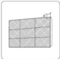
natural_image
Diagram of a 3D grid structure with hatched fill and an arrow pointing to the top-right corner (no text or symbols)Rengør alle filtre
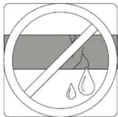
Kontrollér for lækager.
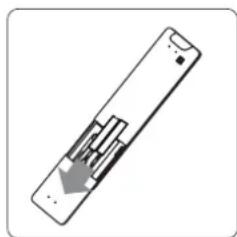
natural_image
Diagram of a remote control panel with internal components and a downward arrow indicating direction (no text or symbols)Udskift batterierne
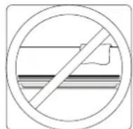
natural_image
Illustration of a hand using a tool to adjust a component, with no visible text or symbols.Bore væghul
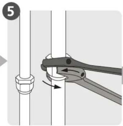
natural_image
Mechanical diagram showing a tool interacting with a bolt and nut (no text or symbols)Tilslut rørledning
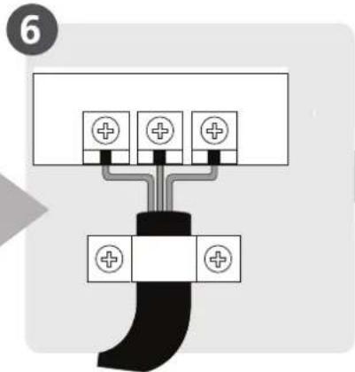
natural_image
Illustration of hands holding a black object with a wavy line in the background (no text or symbols)natural_image
Diagram of a cable being inserted into a wire, showing sheath and clasp components (no text or labels)natural_image
Illustration of two hands holding a rectangular object with horizontal lines and upward arrows, no text or symbols presentBEMÆRK PÅ ILLUSTRATIONER
Enhed: mm (tomme)
Vandret lineal
Lodret lineal
natural_image
Technical line drawings of two air conditioner unit designs with coiled tubing (no text or symbols)BEMÆRK OM R∅RTILSLUTNING
natural_image
Technical line drawing of a mechanical assembly with an inset close-up showing internal components (no text or symbols)natural_image
Simple line drawing of a mechanical joint or bracket with a checkmark (no text or symbols)KORREKT
natural_image
Simple line drawing of a mechanical joint or bracket with a cross symbol (no text or labels)IKKE KORREKT
natural_image
Simple line drawing of a wall-mounted device with a handle and base, no text or symbols presentIKKE KORREKT
natural_image
Simple line drawing of a toilet with a wall and pipe, no text or symbols presentIKKE KORREKT
natural_image
Technical line drawing of a mechanical device showing internal components and housing (no text or symbols)natural_image
Pure technical line drawing of a mechanical assembly with no text or symbols
natural_image
Technical line drawing of a front-end air conditioner unit with labeled dimensions H and W (no text or symbols beyond labels)natural_image
Illustration of a mechanical lever assembly with three plates and a handle (no text or symbols)R∅RUDVIDELSE UDOVER FLARE-FORM
| Udvendig diameterpå røret (mm) | A (mm)Min. Maks. | |
| ∅6,35 (∅0,25") | 0,7 (0,0275") | 1,3 (0,05") |
| ∅9,52 (∅0,375") | 1,0 (0,04") | 1,6 (0,063") |
| ∅12,7 (∅0,5") | 1,0 (0,04") | 1,8 (0,07") |
| ∅16 (∅0,63") | 2,0 (0,078") | 2,2 (0,086") |
| ∅19 (∅0,75") | 2,0 (0,078") | 2,4 (0,094") |
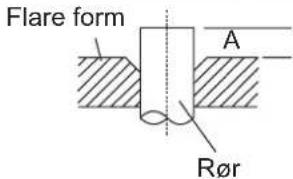
natural_image
Illustration of hands using a tool to lift a mechanical component (no text or symbols)KRAV TORQUE
| Udvendig diameter på røret (mm) | Tilspændingsmoment (N • m) | Flare-dimension (B) (mm) | Flare-form |
| 6,35 ( 0,25 " ) | 18~20 (180~200kgf.cm) | 8,4 ~ 8,7 (0,33 ~ 0,34") | 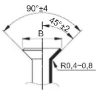 |
| 9,52 ( 0.375 " ) 32~ | 39 (320~390kgf.cm) 13,2~13,5 | (0,52~0,53") | |
| 12,7 ( 0,5 " ) 49~59 | (490~590kgf.cm) 16,2~16,5 | (0,64~0,65") | |
| 16 ( 0,63 " ) 57~7 | 1 (570~710kgf.cm) 19,2~19,7 | (0,76~0,78") | |
| 19 ( 0,75 " ) 67~1 | 01 (670~1010kgf.cm) 23,2~23,7 | (0,91~0,93") |

BRUG IKKE OVERDREVET TORSIONSKRAFT
natural_image
Line drawing of hands using a tool to adjust or install a mechanical component (no text or symbols present)
FORSIGTIG
make yourself at home
Split Air Conditioner ALL EASY PRO
USER MANUAL
POWER SOURCE: 220-240V\~50Hz,1ph RATED INPUT: 2300W

natural_image
Line drawing of a rectangular electronic device with a handle and mounting bracket (no text or symbols)Read this manual carefully before installing or operating your new air conditioning unit. Make sure to save this manual for future reference.
SOMMARIO
natural_image
Illustration of a wrench, screwdriver, gear, and warning sign symbol (no text or labels)natural_image
Diagram of a washing machine with arrows indicating airflow direction (no text or symbols)Attenzione
natural_image
Technical line drawing of a mechanical component or housing (no text or symbols visible)Funzione SLEEP
natural_image
Diagram of a water spray device on a grid panel with a faucet (no text or symbols)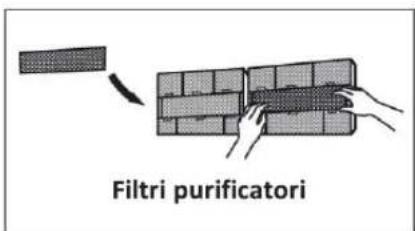
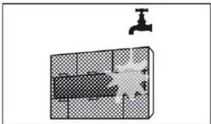
natural_image
Diagram showing a faucet above a grid-patterned room with a submerged object (no text or symbols)Cura e Manutenzione
Pericolo
natural_image
Diagram of a grid-patterned rectangular structure with an arrow indicating a dimension (no text or symbols)natural_image
Simple line drawing of a house with wavy lines inside, no text or symbols presentControllare i cavi
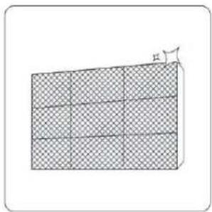
natural_image
Diagram of a 3D grid structure with a small angle labeled 'h' at the top right corner (no text or symbols on the grid itself)natural_image
Line drawing of a smartphone internal component (no text or symbols)natural_image
Prohibition sign with diagonal line and droplet symbols inside a circle (no text)Verificare perdite
natural_image
Technical line drawing of a device with internal components (no text or symbols)natural_image
Two circular diagrams showing a horizontal line and a potted plant inside, both without any text or symbols.natural_image
Pure electrical circuit lines without any symbolsnatural_image
Line drawing of a rectangular electronic device casing (no text or symbols)natural_image
Line drawing of a hard hat with two side clips (no text or symbols)
natural_image
Line drawing of a rectangular electronic device casing with a recessed slot and mounting bracket (no text or symbols)natural_image
Line drawing of a dual-panel air conditioner unit with fan blades and vent slots (no text or symbols)SOMMARIO
natural_image
Simple line drawing of a mechanical component with two parallel rods and a central hub (no text or symbols)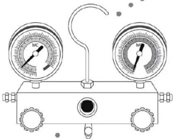
natural_image
Line drawing of a dual-gauge pressure gauge regulator with no text or symbols8 Evacuazione
natural_image
Line drawing of a rectangular electronic device casing with a slot and mounting bracket (no text or symbols)natural_image
Technical line drawing of an air conditioner unit showing internal components and casing (no text or labels)natural_image
Technical line drawing of a mechanical assembly with internal components and an inset close-up (no text or symbols)natural_image
Line drawings of two air purifiers with attached blades and connectors (no text or symbols)natural_image
Pure mechanical diagram showing a bracket and vertical wall with diagonal hatching (no text or symbols)
natural_image
Simple gray circular ring on white background (no text or symbols)
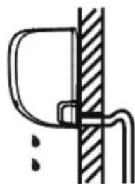
natural_image
Simple line drawing of a mechanical joint or bracket with no text or symbols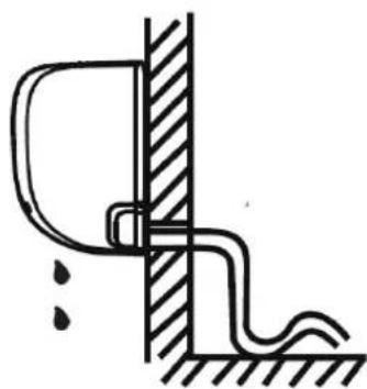
natural_image
Simple line drawing of a pipe connection with a wall and ground, no text or symbols present

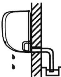
natural_image
Simple line drawing of a door and pipe assembly (no text or symbols)natural_image
Line drawing of a rectangular air conditioner unit with a circular fan and side-mounted buttons (no text or symbols)natural_image
Technical line drawing of a front-end air conditioner unit with fan blades and height dimension (no text or symbols)| Dimensioni unità(W-H-D mm) | A(mm) | B(mm) |
| 681-434-285 | 460 | 292 |
| 700-500-270 | 450 | 260 |
| 780-540-250 | 549 | 276 |
| 845-700-320 | 560 | 335 |
| 810-558-310 | 549 | 325 |
| 700-550-275 | 450 | 260 |
| 770-550-300 | 487 | 298 |
| 800-554-333 | 514 | 340 |
| 845-702-363 | 540 | 350 |
| 900-860-315 | 590 | 333 |
| 945-810-395 | 640 | 405 |
| 946-810-420 | 673 | 403 |
| 946-810-410 | 673 | 403 |
natural_image
Technical line drawing of a mechanical device with a curved panel and lever mechanism (no text or symbols)natural_image
Technical illustration of a mechanical connector assembly showing two stages of thread connection (no text or symbols)natural_image
Technical line drawing of a mechanical clamp or fixture with three plates and a handle (no text or symbols)natural_image
Line drawing of hands using a tool to lift a mechanical component (no text or symbols)| Dimensione tubazione | Coppia serraggio (N/cm) |
| 6.35 mm 1/4 inch | 1500 |
| 9,52 mm 3/8 inch | 2500 |
| 12,7 mm 1/2 inch | 3500 |
| 15,88 mm 3/8 inch | 4500 |
natural_image
Line drawing of a hand using a wrench to adjust or install a mechanical component (no text or symbols present)natural_image
Line drawing of a pressure gauge device with two gauges labeled 'MC' and one connected via a hook (no text or symbols beyond labels)Precauzioni
natural_image
Pure electrical circuit lines without any symbolsmake yourself at home
CE Declaration of Conformity
We, Midea Europe GmbH, with headquarter in Ludwig-Erhard-Straße 14, 65760 Eschborn, fiscal code DE214245812, declare that our product:
Split Type Air Conditioner, All Easy Pro Series, our code:
MSEPBU-09HRFN8-set
MSEPBU-12HRFN8-set
Have been designed and manufactured at:
GD MIDEA AIR-CONDITIONING EQUIPMENT CO., LTD.
Lingang Road Beijiao Shunde Foshan Guangdong, People's Republic of China, 528311
THE PRODUCT IS IN CONFORMITY WITH THE FOLLOWING STANDARDS:
LVD - <2014/35/EU >
EN 60335-2-40:2003+A1:2006+A2:2009+A11:2004+A12:2005+A13:2012
EN 60335-1: 2012 + A11: 2014 + A13: 2017
EN 62233: 2008
EMC - <2014/30/EU >
EN 55014-1: 2017
EN 55014-2: 2015
EN61000-3-2:2014 or EN61000-3-12:2011
EN61000-3-3:2013 or EN61000-3-11:2000
ERP - <2009/125/EC&2017/1369/EU>
EC Regulation 206/2012: 2012-03-06
EC Regulation 626/2011: 2011-05-04
EN 14825:2016
EN 12102:2017
Directive 2011/65/EU
Amendments ROHS Directive (EU) 2015/863