NBGE 125-100-200 - Industrial pump Grundfos - Free user manual and instructions
Find the device manual for free NBGE 125-100-200 Grundfos in PDF.

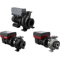
| Product type | Industrial pump with permanent magnet motor variable speed |
| Brand | Grundfos |
| Model | NBGE 125-100-200 |
| Motor | MGE 100-180, three-phase, with integrated PI controller |
| Motor power | From 2.2 kW to 26 kW depending on version and voltage |
| Supply voltage | 3 × 200-240 V or 3 × 380-500 V (depending on model) |
| Protection rating | IP55 (standard), IP66 (option) |
| Insulation class | Class F (155 °C) |
| Ambient operating temperature | -20 °C to +50 °C (depending on voltage and model) |
| Maximum humidity | 95 % (non-condensing) |
| Maximum installation altitude | 3,500 m (with derating above 1,000 m) |
| Pollution degree | 3 |
| Max. number of starts/stops per hour | 10 (via supply) |
| Communication interfaces | Bluetooth (BLE), radio (Glowpan), GENIbus/Modbus RS-485, Ethernet (on FM310/311) |
| Control modes | Proportional pressure, constant pressure, constant temperature, constant differential pressure, constant differential temperature, constant flow, constant level, other constant value, constant curve |
| Safety functions | STO (Safe Torque Off), thermal protection, overload protection, short circuits, phase imbalance |
| Functional module types | FM110, FM310, FM311 (analog/digital inputs/outputs, relays) |
| Accessories (CIM modules) | GENIbus, LonWorks, PROFIBUS DP, Modbus RTU, BACnet MS/TP, Modbus TCP, BACnet IP, PROFINET, EtherNet/IP |
| Power consumption in standby | 5-10 W |
| Weight | Variable depending on configuration; not specified in the manual |
Frequently Asked Questions - NBGE 125-100-200 Grundfos
User questions about NBGE 125-100-200 Grundfos
0 question about this device. Answer the ones you know or ask your own.
Ask a new question about this device
Download the instructions for your Industrial pump in PDF format for free! Find your manual NBGE 125-100-200 - Grundfos and take your electronic device back in hand. On this page are published all the documents necessary for the use of your device. NBGE 125-100-200 by Grundfos.
USER MANUAL NBGE 125-100-200 Grundfos
TPE, TPED Series 1000;
NBE, NBGE, NKE, NKGE;
TPE, TPED, NBE, NKE Series 2000
NBE, NKE Series 2000
Installation and operating instructions
(all available languages)
http://net.grundfos.com/qr/i/92900864
GRUNDFOS

TPE, TPED Series 1000; NBE, NBGE, NKE, NKGE; TPE, TPED, NBE, NKE Series 2000
Français (FR)
5.1 Manutention ..... 1
Modèle K
natural_image
Technical line drawing of a mechanical assembly with no visible text or symbolsTM084303
TM084302
natural_image
Technical line drawing of a mechanical assembly with rollers and a rectangular housing (no text or symbols)
natural_image
Technical line drawing of a mechanical or electronic component with no visible text or symbolsTM084037
Modèle J
Modèle K
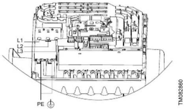
| Pos. Description |
| L1 Phase 1 |
| L2 Phase 2 |
| L3 Phase 3 |
| PE Terre de protection |
natural_image
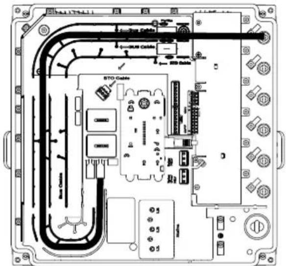
Technical line drawing of an electronic device with internal components and a magnified inset showing labeled parts (no text or symbols present)TM084041
Modèle J
TM082868
Modèle K
natural_image
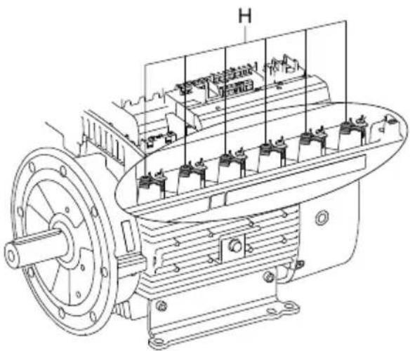
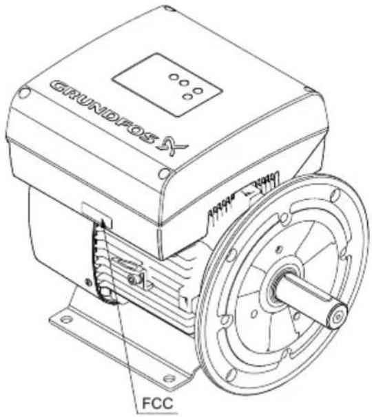
Technical line drawing of an electric motor with internal components and mounting holes (no text or labels)TM082862
natural_image
Technical line drawing of a mechanical assembly with a connector and housing (no text or symbols)Modèle J
natural_image
Technical line drawing of a mechanical component with a terminal block and wiring (no text or symbols)Modèle K
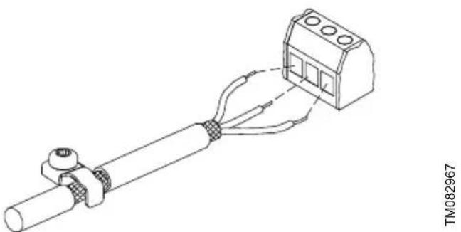
Raccordement recommandé
natural_image
Technical line drawing of a mechanical connector assembly with a close-up view of its internal structure (no text or symbols)natural_image
Technical line drawing of an electric motor with visible stator and rotor assembly (no text or labels)Modèle J
natural_image
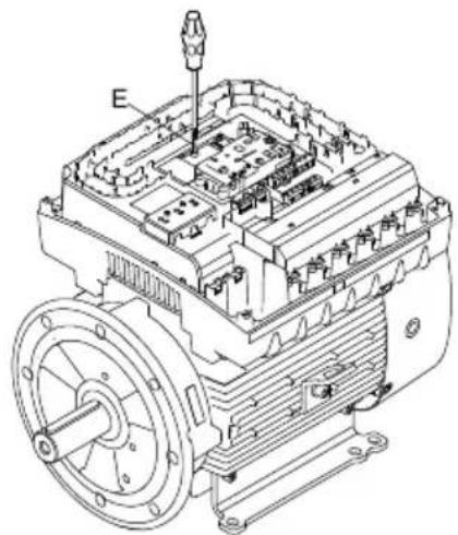
Technical line drawing of an electric motor assembly with labeled component E (no text or symbols beyond label)Modèle K
Modèle J
natural_image
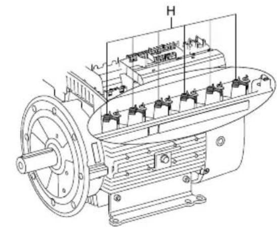
Technical line drawing of an electric motor with visible stator and rotor assembly (no text or labels)Modèle K
TM082868
Modèle K
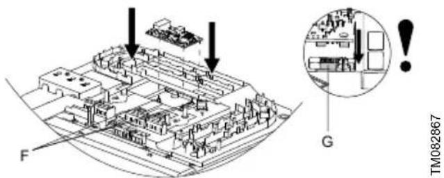
natural_image
Technical line drawing of an electronic device casing with internal components and a magnified inset showing internal structure (no text or symbols)TM084041
Modèle J
Modèle J
TM084101
Modèle J
Modèle K
TM082870
Modèle K
7.2.1 Communication
Réglages régulateur
line
| Q | H | |-------|-------| | Low | High | | High | Low |TM057887 TM057886
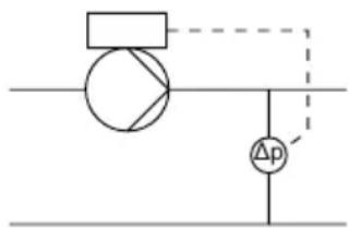
Réglages régulateur
natural_image
Pure electrical circuit lines without any symbolsTM057931
Réglages régulateur
TM057896
TM057965
Réglages régulateur
8.25.23 Assistant installation circulateur
Pos. Description
line
| X | Y | | --- | --- | | 10 | 0 | | 20 | 0 | | 100 | 100 |Pos. Description
line
| Point | X Range | Y Range | |-------|-------------|---------| | ① | 0 to 2 | 2 | | ② | 2 to 4 | 2 | | ③ | 4 to 6 | 2 | | ④ | 6 to 8 | 0 | | ⑤ | 8 to 10 | 0 | | ⑥ | 10 to 12 | 0 |8.25.2 Activer/désactiver la communication radio
8.25.3 Activer/désactiver la communication Bluetooth
La communication radio reste active.
8.25.23 Assistant installation circulateur
• 4-20 mA CC, AL AU.
14.8 Normes applicables
Norme
FEEDBACK92900864
B.1. Installation in the USA and Canada

To maintain the cURus approval, the additional information in this section must be followed.
Environmental enclosure ratings
According to UL 778/C22.2 No 108-14, pumps intended for outdoor use must be marked enclosure type 3 and the product must be tested at a surface temperature down to -31 °F (-35 °C). The MLE Model J enclosure is approved for NEMA type 3 or 4 and is rated at a surface temperature down to 32 °F (0 °C), thus it is only for indoor use in UL 778/C22.2 No 108-14 pump applications.
The MGE, MLE Model K enclosure is approved for NEMA type 12 and is suitable for indoor use only. For more information about ambient temperature during operation, see the sections on operating conditions and ambient temperature.
EMC statements for USA
This equipment has been tested and found to comply with the limits for a Class A digital device, pursuant to part 15 of the FCC Rules. These limits are designed to provide reasonable protection against harmful interference when the equipment is operated in a commercial environment. This equipment generates, uses, and can radiate radio frequency energy and, if not installed and used in accordance with the instruction manual, may cause harmful interference to radio communications. Operation of this equipment in a residential area is likely to cause harmful interference in which case the user will be required to correct the interference at his own expense.

MLE motors of the C2 emission category fulfill the limits of Class A.
This equipment has been tested and found to comply with the limits for a Class B digital device, pursuant to part 15 of the FCC Rules. These limits are designed to provide reasonable protection against harmful interference in a residential installation. This equipment generates, uses, and can radiate radio frequency energy and, if not installed and used in accordance with the instructions, may cause harmful interference to radio communications. However, there is no guarantee that interference will not occur in a particular installation. If this equipment does cause harmful interference to radio or television reception, which can be determined by turning the equipment off and on, the user is encouraged to try to correct the interference by one or more of the following measures:
- Reorient or relocate the receiving antenna.
- Increase the separation between the equipment and receiver.
- Connect the equipment into an outlet on a circuit different from that to which the receiver is connected.
- Consult the dealer or an experienced radio/TV technician for help.

MLE motors of the C1 emission category fulfill the limits of Class B.

MLE motors of the C3 emission category can only be used in industrial plants and public utilities in accordance with FCC § 15.103(b) and ICES 003 § 1.5.1(c). In other locations, MLE motors of the C1 or C2 emission category must be used.
Canadian Interference-Causing Equipment Standard
MLE Model J complies with the Canadian ICES-003 Class B specifications. This Class B device meets all the requirements of the Canadian interference-causing equipment regulations.
MLE Model K complies with the Canadian ICES-003 Class A specifications. This Class A device meets all the requirements of the Canadian interference-causing equipment regulations.
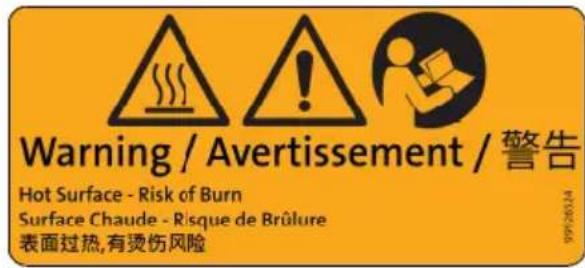
The product might reach a surface temperature of 149 °F (65 °C), therefore pay attention when operating the product.
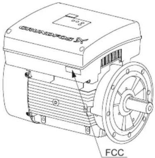
The following marking is found on the product:
TM084167
B.2. Radio communication
For the USA and Canada
CAUTION
Radiation
Minor or moderate personal injury
- This equipment complies with FCC and ISED radiation exposure limits set forth for an uncontrolled environment. This equipment must be installed and operated with a minimum distance of 8 inches (20 cm) between the radiator and your body.

This device complies with Part 15 of the FCC rules and RSS210 of the IC rules.

Changes or modifications made to this equipment not expressly approved by Grundfos may void the FCC authorization to operate this equipment.
Operation is subject to the following two conditions:
• This device may not cause interference.
- This device must accept any interference, including interference that may cause undesired operation of the device.
B.3. Identification numbers
For the USA
Grundfos Holding A/S
Contains FCC ID: OG3-RADIOM01-2G4

Contains FCC ID: OG3-RA2G4MSR.
For Canada
Grundfos Holding A/S
Model: RADIOMODULE 2G4
Contains IC: 10447A-RA2G4M01
Contains IC: 10447A-RA2G4MSR.
Pour le Canada
B.4. Electrical connection
Installation altitude
For corner earthed grid systems: The maximum altitude is 2000 m above sea level.
For all other grid systems: The maximum altitude is 3500 m above sea level.
Conductors
See the sections on electrical installation and cable requirements.
Conductor temperature ratings
Model J: Use minimum 60 °C copper conductors.
Model K: Use 75 °C copper conductors only. The wire sizes for the mains supply must be sized for a wire size which is suitable for at least 125% of the rated input current of the motor drive units.
Conduit hubs
In case of connection to conduit, suitable conduit hubs need to be installed in the field. Such conduit hubs must be UL Listed according to UL Category Code Number (CCN) DWTT/DWTT7 and suitable for the relevant enclosure type rating in accordance with UL 514B and CSA C22.2 No. 18.3.
For type 12 enclosures, it is only allowed to use conduit hubs rated Type 12 or Type 13.
After installation, all unused M20/1/2" NPT openings must remain closed by means of the delivered blind plugs in order to maintain the defined enclosure rating. MGE motors are delivered with M20 blind plugs as standard. MLE motors are delivered with 1/2" NPT blind plugs as standard.
The relevant enclosure type rating can be found on the nameplate of the product.
Recommended ring terminals

Ensure that the used ring terminals are UL certified.
The supply terminals are suitable for field wiring when used with stranded wires and specific listed crimp terminals manufactured by Tyco Electronics (E13288).
| Cable cross-section | Part number/Designation number Manufacturer | |
| [mm^2] | [AWG] | |
| 16 6 130552 Tyco Electronics | ||
| 10 8 160013 Tyco Electronics | ||
| 6 10 130191 Tyco Electronics | ||
Ethernet cable connection
The connection of Ethernet cables must be done by connecting the Ethernet cable screen to an earth clamp on the terminal box, to be in compliance with FCC and ISED requirements.
The recommended Ethernet cable types for earth clamp applications are SF/UTP, S/FTP or SF/FTP, where the cable screen consists of both a braided and a foil screen.
Torques
See the section on torques.
Line reactors
The maximum line reactor size in front of the drive must not exceed the following values:
Model J
| P2 | Maximum line reactor size [mH] |
| [kW] [hp] 1750-2200 rpm | 3500-4000 rpm4000-5900 rpm |
| 2.2 3 - 1.5 | |
| 4 5 0.7 0.7 | |
| 5.5 7.5 0.9 0.3 | |
| 7.5 10 0.6 0.6 | |
| 11 15 0.3 0.3 |
Model K
| P2 | Maximum line reactor size [mH] | ||
| [kW] [hp] 1750-2200 rpm 3400-4000 rpm 3500-4000 rpm | |||
| 7.5 10 | - | 0.2 | - |
| 11 | 15 | 0.3 | 0.2 |
| 15 | 20 | 0.2 | - |
| 18.5 | 25 | 0.2 | - |
| 22 | 30 | 0.2 | - |
| 26 | 35 | 0.2 | - |

Line reactors are often required for six-pulse variable speed drives. Please observe that the MGE, MLE utilize a small DC capacitor concept for lower harmonics and exceeding the maximum inductance may cause resonance between reactor and the MGE, MLE that will reduce the lifetime of the product.
Short-circuit current
Model J: If a short circuit occurs, the motor can be used on a mains supply delivering not more than 5000 RMS symmetrical amperes, 600 V maximum.
Model K: Suitable for use on a circuit capable of delivering not more than 5000 rms symmetrical amperes, when protected by RK1, J or T Class fuses, rated 600 V.
Fuses
Model J: Fuses used for motor protection must be rated for minimum 500 V. Motors up to and including 7.5 kW (10 hp) require class K5 UL-listed fuses. Any UL-listed fuse can be used for motors of 11 kW (15 hp).
Model K: Fuses used for motor protection must be rated for minimum 600 V.

For fuse sizes, see the section on recommended size of fuses.
3 x 380-480 V, MGE Model K
| Motor size [kW] | Recommended [A] | Maximum [A] | Fuse type |
| 11 35 60 | RK1, Class J or T UL listed fuse | ||
| 15 50 80 | RK1, Class J or T UL listed fuse | ||
| 18.5 60 80 | RK1, Class J or T UL listed fuse | ||
| 22 70 80 | RK1, Class J or T UL listed fuse |
3 x 400-480 V, MGE Model K
| Motor size [kW] | Recommended [A] | Maximum [A] | Fuse type |
| 26 80 80 | RK1, Class J or T UL listed fuse |
3 x 200-240 V, MGE Model K
| Motor size [kW] | Recommended [A] | Maximum [A] | Fuse type |
| 7.5 70 80 | RK1, Class J or T UL listed fuse | ||
| 11 80 80 | RK1, Class J or T UL listed fuse |
3 × 440-480 V, MLE Model K
| Motor size[hp] | Recommended[A] | Maximum[A] | Fuse type |
| 15 35 60 | RK1, Class J or T UL listed fuse | ||
| 20 50 80 | RK1, Class J or T UL listed fuse | ||
| 25 60 80 | RK1, Class J or T UL listed fuse | ||
| 30 70 80 | RK1, Class J or T UL listed fuse |
3 x 200-240 V, MLE Model K
| Motor size[hp] | Recommended[A] | Maximum[A] | Fuse type |
| 10 70 80 | RK1, Class J or T UL listed fuse | ||
| 15 80 80 | RK1, Class J or T UL listed fuse |
Branch-circuit protection for MLE Model J
When the pump is protected by a circuit breaker, the circuit breaker must be rated for a minimum voltage of 500 V. The circuit breaker must be of the inverse-time type.
Branch circuit short-circuit protection
For the USA
Integral solid state short-circuit protection does not provide branch circuit protection. Branch circuit protection must be provided in accordance with the National Electrical Code and any additional local codes, or the equivalent.
For Canada
INTEGRAL SOLID STATE SHORT-CIRCUIT PROTECTION DOES NOT PROVIDE BRANCH CIRCUIT PROTECTION. BRANCH CIRCUIT PROTECTION MUST BE PROVIDED IN ACCORDANCE WITH THE CANADIAN ELECTRICAL CODE, PART I.
Overload protection
Degree of overload protection provided internally by the drive, in percent of full-load current: 102 %.
Argentina
Bombas GRUNDFOS de Argentina S.A.
Ruta Panamericana km. 37.500industin
Bosnia and Herzegovina
GRUNDFOS Sarajevo
Zmaja od Bosne 7-7A
BiH-71000 Sarajevo
Iztochna Tangenta street no. 100
BG - 1592 Sofia
Tel.: +359 2 49 22 200
Fax: +359 2 49 22 201
E-mail: bulgaria@grundfos.bg
Canada
GRUNDFOS Canada inc.
2941 Brighton Road
Oakville, Ontario
L6H 6C9
Tel.: +1-905 829 9533
Fax: +1-905 829 9512
China
GRUNDFOS Pumps (Shanghai) Co. Ltd.
10F The Hub, No. 33 Suhong Road
Minhang District
Shanghai 201106 PRC
Tel.: +86 21 612 252 22
Fax: +86 21 612 253 33
Columbia
GRUNDFOS Colombia S.A.S.
GRUNDFOS Sales Czechia and Slovakia
s.r.o.
Čajkovského 21
779 00 Olomouc
Unit 1, Ground floor, Siu Wai industrial
Centre
29-33 Wing Hong Street & 68 King Lam
Street, Cheung Sha Wan
Kowloon
Tel.: +852-27861706 / 27861741
Fax: +852-27858664
Hungary
GRUNDFOS South East Europe Kft.
Tópark u. 8
H-2045 Törökbálint
Tel.: +36-23 511 110
Fax: +36-23 511 111
India
GRUNDFOS Pumps India Private
Limited
118 Old Mahabalipuram Road
Thoraipakkam
Chennai 600 097
Tel.: +91-44 2496 6800
Indonesia
PT GRUNDFOS Pompa
Graha intirub Lt. 2 & 3
Jln. Cililitan Besar No.454. Makasar,
Jakarta Timur
ID-Jakarta 13650
Tel.: +62 21-469-51900
Fax: +62 21-460 6910 / 460 6901
Ireland
GRUNDFOS (Ireland) Ltd.
Unit A, Merrywell Business Park
Ballymount Road Lower
Dublin 12
Tel.: +353-1-4089 800
Fax: +353-1-4089 830
Italy
GRUNDFOS Pompe Italia S.r.l.
Via Gran Sasso 4
6th Floor, Aju Building 679-5
Yeoksam-dong, Kangnam-ku, 135-916
Seoul, Korea
Tel.: +82-2-5317 600
Fax: +82-2-5633 725
Latvia
SIA GRUNDFOS Pumps Latvia
Deglava biznesa centrs
7 Jalan Peguam U1/25
Glenmarie industrial Park
40150 Shah Alam, Selangor
Tel.: +60-3-5569 2922
Fax: +60-3-5569 2866
Mexico
Boulevard TLC No. 15
GRUNDFOS Netherlands
Veluwezoom 35
1326 AE Almere
Postbus 22015
1302 CA ALMERE
Tel.: +31-88-478 6336
North Harbour Industrial Estate
Albany, Auckland
Tel.: +64-9-415 3240
Fax: +64-9-415 3250
Norway
GRUNDFOS Pumper A/S
Strømsveien 344
Postboks 235, Leirdal
N-1011 Oslo
Tel.: +47-22 90 47 00
Fax: +47-22 32 21 50
Poland
GRUNDFOS Pompy Sp. z o.o.
ul. Klonowa 23
16 Lascelles Drive, Meadowbrook Estate
1609 Germiston, Johannesburg
Tel.: (+27) 10 248 6000
Fax: (+27) 10 248 6002
E-mail: lgradidge@grundfos.com
Spain
7 Floor, 219 Min-Chuan Road
Taichung, Taiwan, R.O.C.
Tel.: +886-4-2305 0868
Fax: +886-4-2305 0878
Thailand
GRUNDFOS (Thailand) Ltd.
92 Chaloem Phrakiat Rama 9 Road
Dokmai, Pravej, Bangkok 10250
Tel.: +66-2-725 8999
Fax: +66-2-725 8998
Turkey
GRUNDFOS POMPA San. ve Tic. Ltd. Sti.
United Arab Emirates
GRUNDFOS Gulf Distribution
P.O. Box 16768
Jebel Ali Free Zone, Dubai
Tel.: +971 4 8815 166
Fax: +971 4 8815 136
United Kingdom
GRUNDFOS Pumps Ltd.
Grovebury Road
Leighton Buzzard/Beds. LU7 4TL
Tel.: +44-1525-850000
Fax: +44-1525-850011
U.S.A.
Global Headquarters for WU
856 Koomey Road
Brookshire, Texas 77423 USA
Phone: +1-630-236-5500
Uzbekistan
Grundfos Tashkent, Uzbekistan
The Representative Office of Grundfos
Kazakhstan in Uzbekistan
38a, Oybek street, Tashkent
Tel.: (+998) 71 150 3290 / 71 150 3291
Fax: (+998) 71 150 3292
9290086407.2024
ECM: 1386564