
H-10152 - Vacuum Cleaner Uline - Free user manual and instructions
Find the device manual for free H-10152 Uline in PDF.

User questions about H-10152 Uline
0 question about this device. Answer the ones you know or ask your own.
Ask a new question about this device
Download the instructions for your Vacuum Cleaner in PDF format for free! Find your manual H-10152 - Uline and take your electronic device back in hand. On this page are published all the documents necessary for the use of your device. H-10152 by Uline.
USER MANUAL H-10152 Uline
natural_image
Line drawings of three different tools: a screwdriver, a tool with a handle, and a pair of pliers (no text or symbols)Phillips Screwdriver 3/8" Socket Wrench Pliers
natural_image
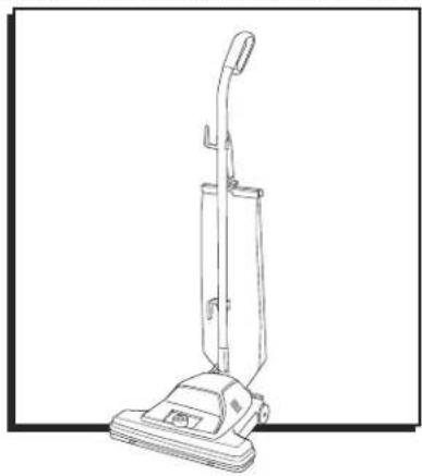
Line drawing of a vacuum cleaner (no text or symbols present)SAFETY

IMPORTANT! Read all instructions before using this vacuum.

WARNING! To reduce the risk of fire, electric shock or injury, basic precautions should be observed, including the following:
- Connect to a properly grounded outlet only. See grounding instructions on page 2. Do not modify the three-prong grounded plug.
- Do not leave vacuum when it is plugged in. Unplug from outlet when not in use and before servicing.
- Do not use outdoors or on wet surfaces.
- Do not use motorized nozzle on wet surfaces.
- Do not allow to be used as a toy. Plastic film can be a suffocation hazard. Close attention is necessary when used by or near children.
- Do not use for any purpose other than described in these instructions.
- Do not use with damaged cord or plug. If vacuum is not working as it should, has been dropped, damaged, left outdoors or dropped into water, do not attempt to operate; have it repaired at an authorized service center.
- Do not pull or carry by cord, use cord as a handle, close door on cord or pull cord around sharp edges or corners. Do not run vacuum over cord. Keep cord away from heated surfaces.
- Do not unplug by pulling on cord. To unplug, grasp the plug, not the cord.
-
Do not handle plug or vacuum with wet hands.
-
Do not put any object into openings. Do not use with any opening blocked. Keep openings free of dust, lint, hair or anything that may reduce airflow.
- Keep hair, loose clothing, fingers and all parts of body away from openings and moving parts of the vacuum and its accessories.
- Turn vacuum off before plugging or unplugging.
- Use extra care when cleaning on stairs.
- Do not use to pick up flammable or combustible materials (lighter fluid, gasoline, kerosene, etc.) or use in areas where they may be present.
- Do not pick up anything that is burning or smoking, such as cigarettes, matches or hot ashes.
- Do not use without dust bag and/or filters in place.
- Use only three-wire SJT extension cords that have three-prong grounding plugs and grounding receptacles that fit the vacuum plug.
- Ensure extension cord is in good condition and is the correct size for your vacuum.
- Maintain vacuum with care – inspect extension cords periodically and replace if damaged.
- Do not turn your vacuum on until you are familiar with all instructions and operating procedures. Keep vacuum on a level surface.
- Do not use vacuum in an enclosed space filled with vapors given off by oil-based paint, paint thinner, some moth-proofing substances, flammable dust or other explosive or toxic vapors.
- Do not use to pick up toxic material (chlorine bleach, ammonia, drain cleaner, etc.).
- Do not pick up hard or sharp objects such as glass, nails, screws, coins, etc.
SAFETY CONTINUED
STOP
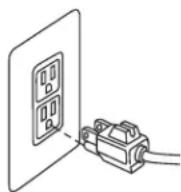
WARNING! Improper connection of the equipment-grounding conductor can result in a risk of electrical shock. Check with a qualified electrician or service person if you aren't sure if the outlet is properly grounded. Do not modify the plug. If it will not fit the outlet, have a proper outlet installed by a qualified electrician. This vacuum is designed for use on a nominal 120-volt circuit and has a grounding attachment plug that looks like the plug in the drawing at right. Ensure the appliance is connected to an outlet having the same configuration as the plug. No plug adapter should be used with this vacuum.
GROUNDING INSTRUCTIONS
This vacuum must be connected to a grounded wiring system. If it should malfunction or break down, grounding provides a safe path of least resistance for electrical current, reducing the risk of electrical shock.

NOTE: The cord for this vacuum has an equipment-grounding conductor and a grounding plug. It must only be plugged into an outlet that is properly installed and grounded in accordance with all local codes and ordinances.
ASSEMBLY

CAUTION! Assemble vacuum fully before using.
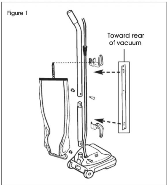
- Slide upper handle and lower handle together so handle bolt holes are positioned as shown in Figure 1. Insert a two-part bolt in center of handle and tighten. Hold assembled handle so handle curves away from vacuum. Place lower handle into handle socket at rear of vacuum. Align holes. Insert two-part bolt and tighten using Phillips screwdriver. (See Figure 1)
text_image
Figure 1 Toward rear of vacuum-
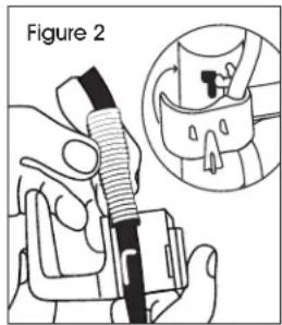
Pull the spring on the electrical cord upward toward the top of the handle. Insert the lower half of the spring into the upper cord hook. Snap the hook into the upper handle. (See Figure 2)
-
Insert the power cord into the lower cord hook. Snap into lower handle. Pull on the cord to tighten but leave enough slack near the base so the cord is not strained when the handle is lowered. (See Figure 3)
text_image
Figure 2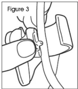
natural_image
Medical illustration showing a hand holding a cable with a magnified view of the cable (no text or symbols present)ASSEMBLY CONTINUED
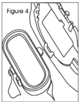
- Insert bag adapter clip on bottom of bag collar into bag adapter retainer. (See Figure 4)
natural_image
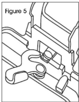
Line drawing of a mechanical component with a looped part and attached parts (no text or symbols)- Push bag collar up and forward so the locator lug slides into slot. Turn cam latch to lock bag onto rivet. Attach bag spring to back of the upper cord hook. Attach chain to the two zippers. (See Figure 5)
natural_image
Technical line drawing of a mechanical component with no visible text or symbolsOPERATION
POWER CORD
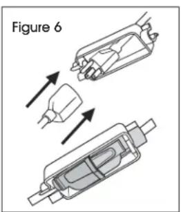
Attach extension cord to power cord and secure with cord lock provided. (See Figure 6)
text_image
Figure 6HANDLE ADJUSTMENT
- Step on handle release located at the left rear side of vacuum.
- Move handle and adjust it to desired position.
- Step on the handle release a second time to allow the handle to lay flat for cleaning under low furniture.
HEIGHT SETTINGS

WARNING! To prevent injury, keep loose clothing, hair, fingers and all other parts of body away from any moving part (such as the revolving brush). Turn cleaner off and unplug before changing the height.
- With power cord unplugged, adjust base to highest setting with six-position adjustment knob.
- Plug in vacuum, step on power switch and turn on vacuum. Lower setting one notch at a time until you hear bristles touching the carpet. This should be a noticeable sound change.
| Carpet HeightRecommended Setting | |||
| Position | 1-2 | ...... | Low pile |
| Position | 3-4 | ...... | Medium pile |
| Position | 5-6 | ...... | High pile |

CAUTION! With brush roll on, do not allow vacuum to sit in one location for an extended period of time, as damage to floor can result.

NOTE: When finished using vacuum, wrap cord around cord wrap for storage. Store vacuum indoors in a dry location in an area where it is not likely to get damaged.
MAINTENANCE
CHANGING THE DUST BAG
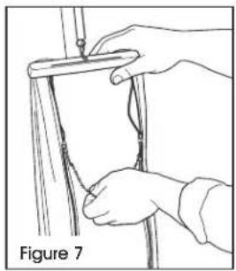
- Grasp top of bag and release both zippers by pulling down on dual zipper connector. (See Figure 7)
natural_image
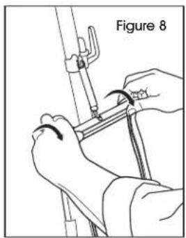
Illustration of hands holding a pole with a ruler, labeled Figure 7 (no text or symbols on the diagram itself)- Release bag cap by grasping finger tabs and rotating the cap toward back of bag. (See Figure 8)
natural_image
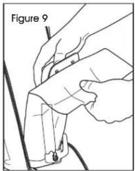
Illustration of hands using a tool to adjust or install a mechanical component, labeled 'Figure 8' (no text or symbols on the diagram itself)- Support the top of the dirt tube and pull the dust bag collar forward. (See Figure 9)
text_image
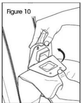
Figure 9- Place new dust bag collar on the tabs of the dirt tube interface. Rotate up until dirt tube tabs fasten into holes in dust bag collar. (See Figure 10)
natural_image
Illustration of hands fastening a car seatbelt using a clamp (no text or symbols)-
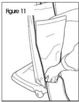
Tuck bottom of dust bag into the lower portion of the outer bag. (See Figure 11)
-
Replace the bag cap and pull up on the dual zipper connector to secure the back of the outer bag. (See Figure 12)
natural_image
Line drawing of a person using a tool to cut a piece of material, labeled 'Figure 11' (no text or symbols on the diagram itself)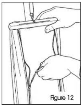
natural_image
Illustration of hands tying a knot between two vertical poles, labeled Figure 12 (no text or symbols on diagram)MAINTENANCE CONTINUED
REPLACING A WORN BELT

WARNING! Belt pulleys can become hot during normal use. To prevent burns, avoid touching the belt pulley when servicing the drive belt.
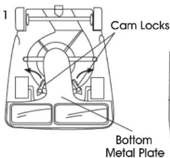
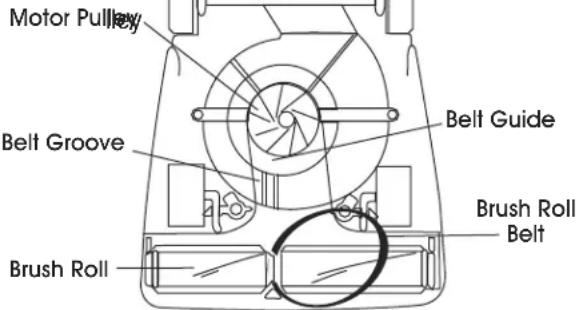
- Release cam locks (1) and remove bottom plate. Pull up on belt to rotate it off motor pulley. Lift up on brush roll and remove worn belt. Place new belt around the brush roll. Align brush roll belt (3) with belt guide. (See Figure 13)
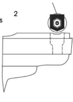
- Ensure rubber end cap cover (2) is installed correctly. Align end caps with slots in vacuum base. Push brush roll into base. (See Figure 13)
- Place lower side of belt into belt guide and pull to stretch the belt around the left side of the motor pulley. Rotate pulley to secure the belt into the groove. Replace bottom plate and secure with cam locks. (See Figure 13)
Figure 13
text_image
1 Cam Locks Bottom Metal PlateRubber End Cap Cover
text_image
23
text_image
Motor Pulley Belt Groove Belt Guide Brush Roll Brush Roll BeltREPLACING BRISTLE STRIPS
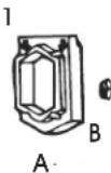
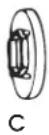
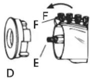
- Remove rubber end cap cover (A) from one end. Unscrew locknut (B). Remove end cap (C) – sleeve bearing brush roll includes a shaft washer not shown. (See Figure 14)
- Remove bearing retainer (D). Push shaft (E) through opposite end. Pull out worn bristle strip (F) with pliers. Slide in new bristle strip of same length (rounded end first). (See Figure 14)
Figure 14
2
- Fit track on either side of the bristle strip into the brush roll slot. Replace the second strip from opposite end of brush roll.
- Replace shaft. Align indentation on bearing retainer with bristle strip on both ends of brush roll. Reassemble the remainder of brush roll and secure into the base.

CAUTION! Turn off the switch and unplug the electrical cord before maintenance.

IMPORTANT! Improper installation of the brush roll or brush roll belt could cause carpet or vacuum damage.
MAINTENANCE CONTINUED
CLEARING A BLOCKAGE
CLEARING CLOG IN DIRT TUBE
- Remove the dust bag (refer to page 4).
- Remove the outer bag flange from the base of the vacuum. Use a tool or hanger to push any debris completely through the dirt tube to remove clog. If the tube is not clogged, check the bottom of the vacuum and the brush roll.
- Turn cleaner upside down. Clip strings with scissors.

NOTE: If necessary, release the cam locks and remove the bottom metal plate. Clear debris around the brush roll. (See Figure 15)
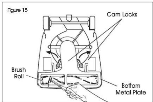
text_image
Figure 15 Cam Locks Brush Roll Bottom Metal PlateCLEARING CLOG IN FAN CHAMBER
-
If a clog is not around the brush roll, there may be a clog in the clear fan chamber.
-
If you see a clog, release two cam locks and remove bottom plate. (See Figure 15)
- Remove the two screws to release the clear fan cover.

NOTE: Use a hanger to help release the clog around the fan, but do not remove the fan. (See Figure 16)
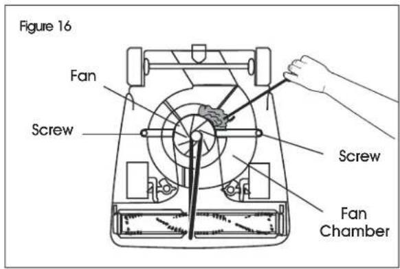
text_image
Figure 16 Fan Screw Screw Fan ChamberTROUBLESHOOTING
| OPERATING ISSUE RECOMMENDATIONS | |
| Motor will not start. Turn power switch on. | Push plug securely into outlet.Try another outlet. |
| Little or no suction. A clog may be in the bottom of the vacuum or in the dirt tube.Remove bottom metal plate and check for clogs in base or brush roll.Unzip cloth bag, remove dust bag and check for clogs in the dirt tube.Belt may be broken. Replace belt. | |
TROUBLESHOOTING CONTINUED
| OPERATING ISSUE RECOMMENDATIONS | |
| Vacuum does not clean. Dust bag may be full. | Replace the dust bag if 2/3 or more full.Adjust carpet height setting to lower position.Check for clogs that restrict airflow.Check for worn or broken belt and replace if necessary. |
| Vacuum is hard to push. Adjust carpet height setting to higher position. | |
| Vacuum is clogged. Remove bottom metal plate. | Check for clog in base and/or brush roll.Remove dust bag. Check for clog where dust bag attaches to dust bag collar and where the dust bag attaches to the dirt tube. |
| Burning smell. The belt may be damaged or something may be caught in the brush roll.Check brush roll and remove obstruction.Replace belt. | |
| Dust leaking out of vacuum. Check to ensure paper bag collar is properly attached inside cloth bag.Check paper bag for tears. | |
| Belt is broken or worn. Replace belt. | |
| Belt continues to break. The brush roll should be positioned with the low side of belt aligned within the belt groove. | |
natural_image
Line drawing of a vacuum cleaner with handle and base (no text or symbols)SEGURIDAD

natural_image
Line drawing of hands holding a tool over a cylindrical object, labeled 'Diagrama 7' (no text or symbols on the diagram itself)natural_image
Illustration of hands tying a knot between two vertical poles, labeled 'Diagrama 12' (no text on diagram itself)natural_image
Line drawings of three different tools: a screwdriver, a wrench, and a pair of pliers (no text or symbols present)natural_image
Line drawing of a vacuum cleaner (no text or symbols present)SÉCURITÉ

natural_image
Medical illustration showing a hand operating a cable with a labeled section (Figure 3), no text or symbols present.natural_image
Technical line drawing of a mechanical component labeled Figure 4, showing a looped spring-like structure with mounting brackets (no text or symbols beyond label)natural_image
Technical line drawing of a mechanical component with no visible text or symbolsFONCTIONNEMENT
CORDON D'ALIMENTATION
natural_image
Line drawing of hands holding a tool over a cylindrical object, labeled 'Figure 7' (no text or symbols on the diagram itself)natural_image
Line drawing of a person using a tool to cut a piece of material, labeled 'Figure 11' (no text or symbols on the diagram itself)natural_image
Illustration of hands using a tool to adjust or install a mechanical component, labeled 'Figure 8' (no text or symbols on the diagram itself)natural_image
Illustration of hands using a tool to draw or attach a cable or wire, labeled 'Figure 12' (no text on diagram itself)natural_image
Illustration of hands adjusting a mechanical component with a curved arrow indicating rotation (no text or symbols)ENTRETIEN SUITE
REMPLACEMENT D'UNE COURROIE USÉE


