H-11640 - Lifting magnet Uline - Free user manual and instructions
Find the device manual for free H-11640 Uline in PDF.

User questions about H-11640 Uline
0 question about this device. Answer the ones you know or ask your own.
Ask a new question about this device
Download the instructions for your Lifting magnet in PDF format for free! Find your manual H-11640 - Uline and take your electronic device back in hand. On this page are published all the documents necessary for the use of your device. H-11640 by Uline.
USER MANUAL H-11640 Uline
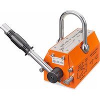
ULINE H-11640, H-11641 LIFTING MAGNET
1-800-295-5510 uline.com
TOOL NEEDED
Allen Wrench (included)
natural_image
Line drawing of a mechanical clamp or lever device (no text or symbols)SAFETY
STOP
WARNING! Read the manual carefully before using. Do not exceed rated weight while using.
- Ensure you have selected the correct lifting magnet based on your needed lifting capacity.
-
Ideal environment for use of lifting magnets:
-
Ambient air temperature no higher than 176°F – not for use in extreme conditions.
- No violent vibration – this could impact magnet performance.
-
No aggressive chemicals present – this could corrode lifting magnets.
-
Do not pull the handle if no steel material is under the lifting magnet.
-
Lifting magnet should lift no higher than 5'. Do not lift items over people or equipment.
-
Do not move workpiece until properly hoisted into the air.
- Before each use, check connections of steel string, shaft, pawls and clasp. If damaged, repair before use.
- Keep magnets clean and clear of dust and debris.
- Avoid bumping during lifting and moving to prevent damage to lifting magnet.
- Inspect lifting magnets annually to confirm they are not in need of maintenance or replacement.
- Ensure the handle's slide key is locked by lifter's stop pin.
- Can be harmful to pacemaker wearers and others with medical implants.
SPECIFICATIONS
PRODUCT SPECS
text_image
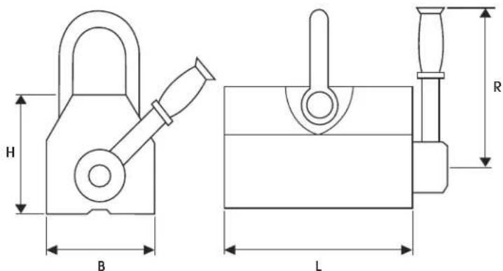
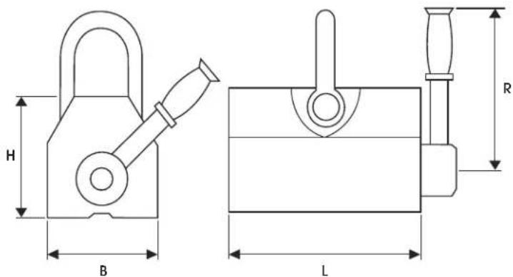
H B L R| MODEL | RATED LIFTING CAPACITY SHAPE SIZE | TEST MAXPULL OFF FORCE | WEIGHT | |||||
| STEEL PLATE ROUND STEEL L B H | R | |||||||
| H-11640 | 660 lbs. | 330 lbs. | 6.5" | 3.9" | 3.9" | 8.8" | 2,315 lbs. | 26 lbs. |
| H-11641 | 1,320 lbs. | 660 lbs. | 8.9" | 4.6" | 5.0" | 10.1" | 4,630 lbs. | 54 lbs. |
SPECIFICATIONS CONTINUED
CAPACITY GUIDELINES
| STEEL PLATE THICKNESS LIFTING | CAPACITY | |||
| mm inch | H-11640 H-11641 | |||
| T1 | ≤ 80 | ≤ 3.15 | 100% 100% | |
| T2 60 | 2.36 | |||
| T3 | 55 | 2.16 | ||
| T4 | 50 | 1.97 | ||
| T5 45 | 1.77 | |||
| T6 40 | 1.57 | |||
| T7 35 | 1.38 | |||
| T8 30 | 1.18 | |||
| T9 | 25 | 0.98 | 90% | |
| T10 | 20 | 0.79 | 90% | 75% |
| T11 | 15 | 0.59 | 70% | 60% |
| T12 | 10 | 0.39 | 50% | 45% |
| T13 | 5 | 0.20 | 30% | 25% |
ASSEMBLY
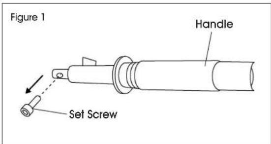
HANDLE ASSEMBLY
- Remove set screw from handle. (See Figure 1)
text_image
Figure 1 Handle Set Screw- Insert handle into housing and secure with previously removed set screw. (See Figure 2)

NOTE: Ensure handle lock mechanism faces inward toward the magnet.
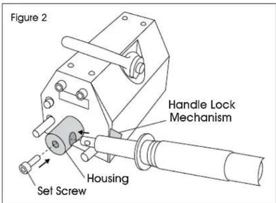
text_image
Figure 2 Handle Lock Mechanism Housing Set Screw- Tighten set screw with included Allen wrench. (See Figure 3)
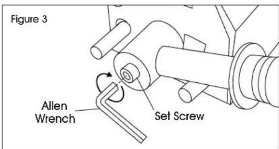
text_image
Figure 3 Allen Wrench Set ScrewOPERATION

NOTE: Lifting magnets do not need exterior power supply.

NOTE: Magnets can hold both flat plates and round pipes.

NOTE: Consider center of gravity. Workpiece length should be less than 118".
DURING LIFTING
- Place lifting magnet on flat surface of your workpiece.
- Pull handle from "OFF" to "ON" and ensure it locks in place. (See Figure 4)
- Attach hoist hook to top ring on the lifting magnet. (See Figure 5)

NOTE: For round pipes, place the lifting magnet against the surface of your round workpiece. The v-groove on the bottom of the magnet will be the main contact point. Round pipes have reduced lifting capacity. Consult the capacity chart before operation.
AFTER LIFTING
- Press button on top of the handle and pull handle from "ON" to "OFF" position. (See Figure 6)
- Remove lifting magnet from your workpiece.
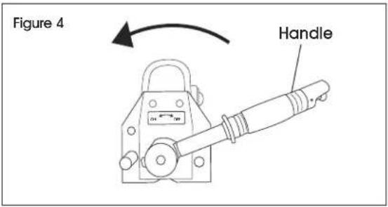
text_image
Figure 4 Handle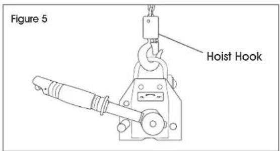
text_image
Figure 5 Hoist Hook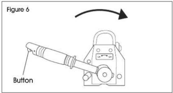
text_image
Figure 6 ButtonSEGURIDAD

CARACTÉRISTIQUES DU PRODUIT
text_image
H B L R| MODÈLE | CAPACITÉ DE LEVAGE NOMINALE TAILLE | DE LA FORME | FORCE DE TRACTION MAXIMALE | POIDS | ||||
| PLAQUE D'ACIER ACIER ROND | L B | H | R | |||||
| H-11640 | 299,4 kg (660 lbs.) | 149,7 kg (330 lbs.) | 16.5 cm(6,5 po) | 9.9 cm(3,9 po) | 9.9 cm(3,9 po) | 22.4 cm(8,8 po) | 1 050 kg (2 315 lbs.) | 11,8 kg(26 lbs) |
| H-11641 | 598,7 kg (1 320 lbs.) | 299,4 kg (660 lbs.) | 22.6 cm(8,9 po) | 11.7 cm(4,6 po) | 12.7 cm(5,0 po) | 25.7 cm(10,1 po) | 2 100 kg (4 630 lbs.) | 24,5 kg(54 lbs) |