H-10160 - Flat screen mount Uline - Free user manual and instructions
Find the device manual for free H-10160 Uline in PDF.

User questions about H-10160 Uline
0 question about this device. Answer the ones you know or ask your own.
Ask a new question about this device
Download the instructions for your Flat screen mount in PDF format for free! Find your manual H-10160 - Uline and take your electronic device back in hand. On this page are published all the documents necessary for the use of your device. H-10160 by Uline.
USER MANUAL H-10160 Uline
WALL MONITOR MOUNT – 32-80" TILTING
1-800-295-5510
uline.com
natural_image
Technical line drawing of a mechanical frame assembly with two vertical supports and mounting holes (no text or symbols)TOOLS NEEDED
Electric Drill

Phillips Head
Drill Bit

3/16" Drill Bit
3/8" Drill Bit

Magnetic Level (included)
Tape Measure
Phillips
Screwdriver

13 mm Socket
Stud Finder

Two-Person Assembly Recommended
PARTS

Bracket x 2
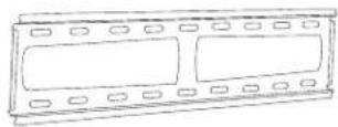
Wall Plate x 1

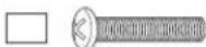
Square Washer x 4
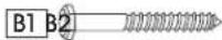
Lag Screw x 4
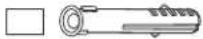
Plastic Anchor x 4
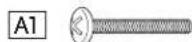
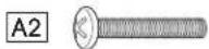
M4 x 25 mm Bolt x 4 M5 x 25 mm Bolt x 4
M6 x 25 mm Bolt x 4 M8 x 25 mm Bolt x 4
INSTALLATION
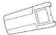
- Attach plastic covers to both ends of the wall plate. (See Figure 1)
Figure 1
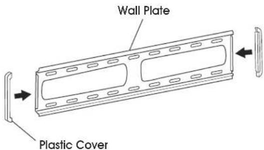
text_image
Wall Plate Plastic CoverATTACHING TO CONCRETE WALL
- Align wall plate in desired location. Place level on top of wall plate to ensure it is leveled correctly. Mark where holes for screws are to be located. (See Figure 2)
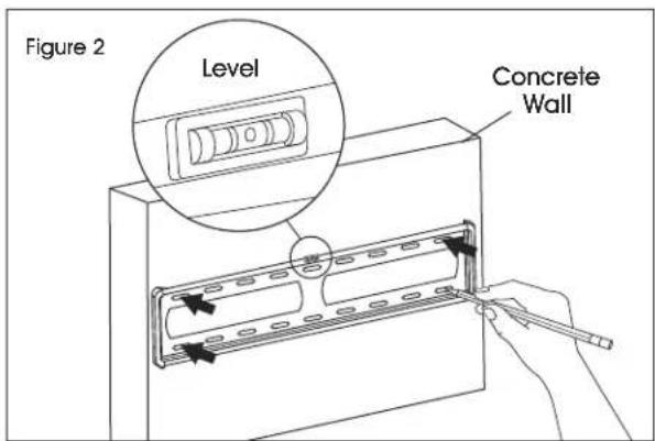
text_image
Figure 2 Level Concrete WallINSTALLATION CONTINUED
- Drill holes 2 ^3/8 " deep using 3/8" drill bit. Insert plastic anchors (B2) into the pre-drilled holes. (See Figure 3)

NOTE: It is recommended to use a masonry drill bit for concrete walls.
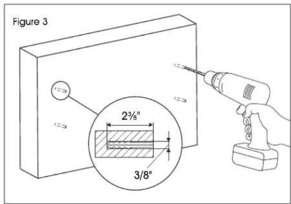
text_image
Figure 3 2³/8" 3/8"- Keep magnetic level attached to wall plate. Using a drill and 13 mm socket, install wall plate onto wall using lag screws (B1) and washers (B3). (See Figure 4)
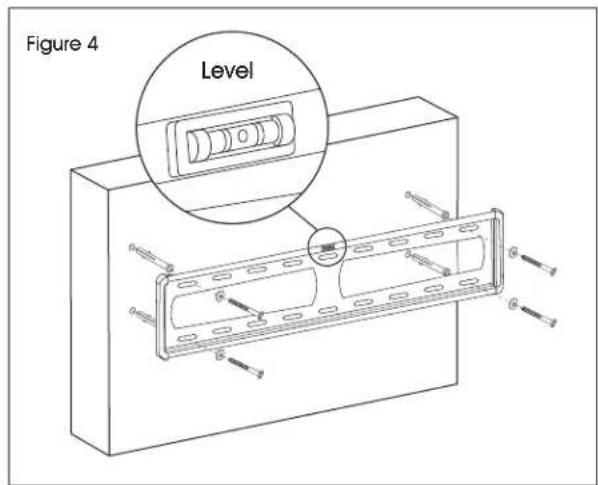
text_image
Figure 4 LevelATTACHING TO DRYWALL

STOP! If mounting to drywall, brackets must be properly attached to wood studs behind the wall.
-
Using stud finder, locate studs that will be used for mounting. Studs are commonly spaced 16" center-to-center. At roughly the desired location and height, mark where studs are located.
-
Align wall plate with studs and move to desired location. Place level on top of the wall plate to ensure it is leveled correctly. Mark where holes for screws are to be located. (See Figure 5)
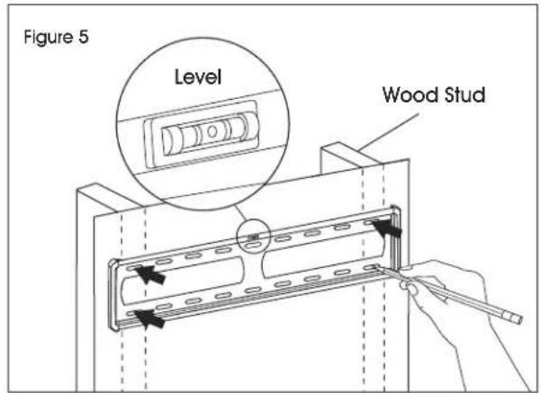
text_image
Figure 5 Level Wood Stud- Drill holes 2" deep using 3/16" drill bit. (See Figure 6)
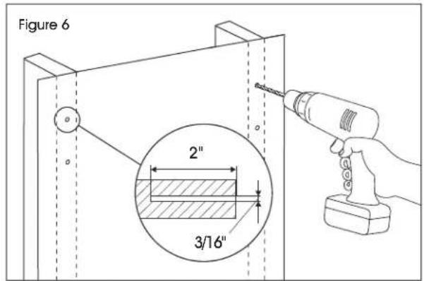
text_image
Figure 6 2" 3/16"- Keep magnetic level attached to wall plate. Using a drill and 13 mm socket, install wall plate onto wall using lag screws (B1) and washers (B3). (See Figure 7)
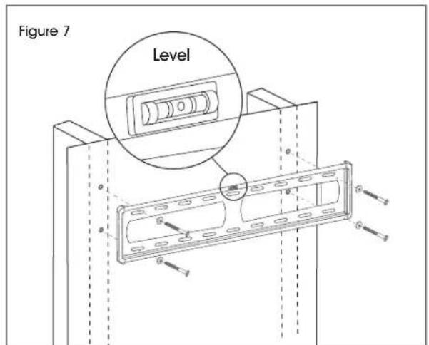
text_image
Figure 7 LevelINSTALLATION CONTINUED
ATTACHING BRACKETS TO MONITOR
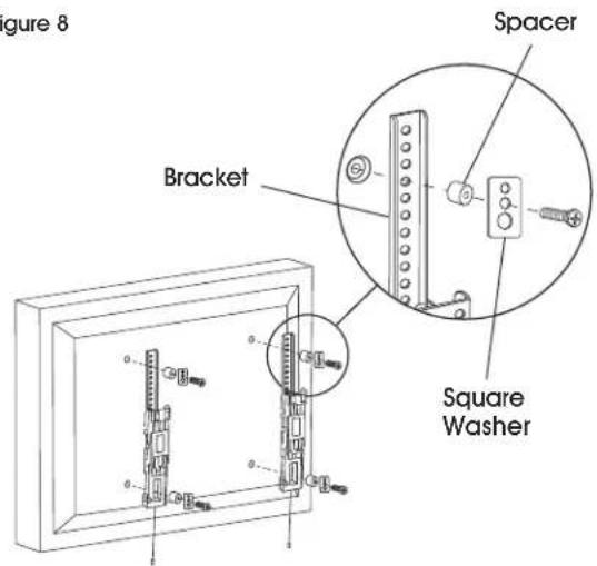
Determine screw size that is compatible with the monitor. Using the square washers (A6) and spacers (A5), install each bracket to the monitor.
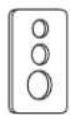
SQUARE WASHER
Small hole for M4 screws (A1)
Medium hole for M5 and M6 screws (A2, A3)
Large hole for M8 screws (A4)

NOTE: For monitors with flat backs, use spacers (A5) on the outside of brackets. (See Figure 8)
Figure 8
text_image
Figure 8 Spacer Bracket Square Washer
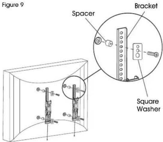
NOTE: For monitors with a curved back or obstructions, place spacers (A5) on the side closest to the monitor. (See Figure 9)
text_image
Figure 9 Spacer Bracket Square WasherMOUNTING MONITOR TO WALL PLATE
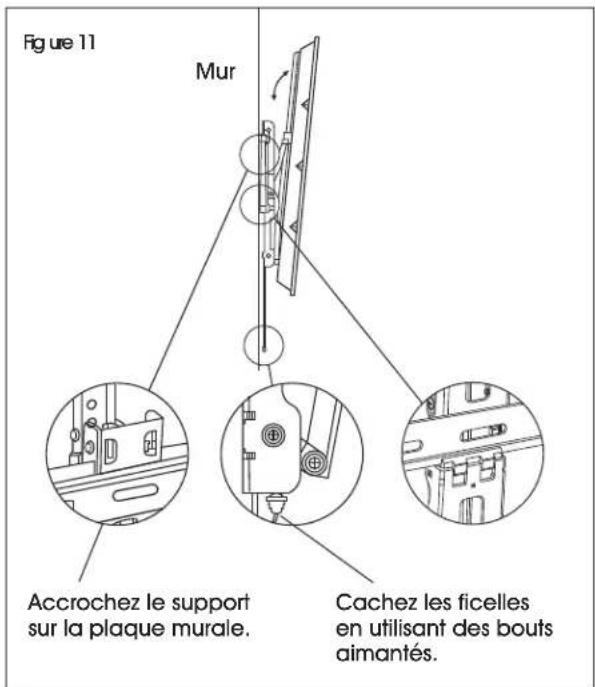
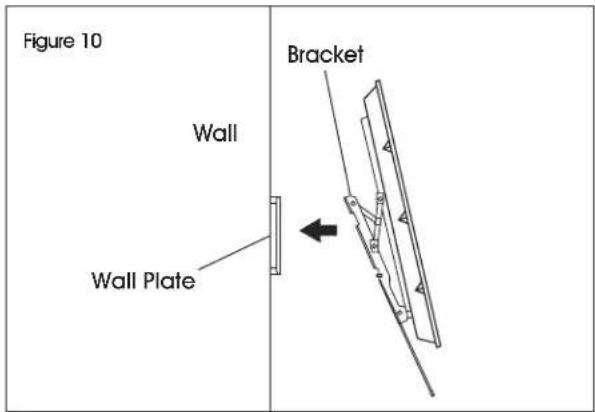
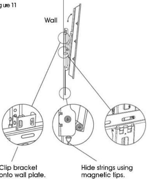
With second person, carefully lift and align brackets on the monitor with the wall plate. The brackets will clip into the wall plate and lock into position. (See Figures 10-11)

NOTE: Strings that are used to release the monitor from the mount may be visible after installation. These can be hidden behind the monitor using the magnetic tips.
text_image
Figure 10 Wall Wall Plate BracketFigure 11
text_image
Figure 11 Wall Clip bracket onto wall plate. Hide strings using magnetic tips.INSTALLATION CONTINUED
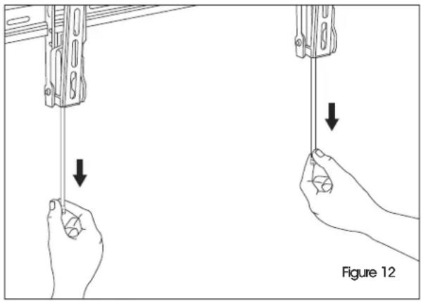
REMOVING THE MONITOR
With second person, pull down on the strings attached to the brackets. This will unlock the brackets from the wall plate, and the monitor can be removed. (See Figure 12)
natural_image
Illustration of two hands holding a device with downward arrows indicating motion, labeled Figure 12 (no text or symbols on the devices themselves)ULINE H-10160
800-295-5510
uline.mx
SOPORTE DE PARED PARA | uline.m2 PANTALLA – INCLINABLE DE 32-80"
natural_image
Technical line drawing of a mechanical frame assembly with two vertical supports and mounting holes (no text or symbols)natural_image
Technical line drawing of a mechanical frame assembly with two vertical supports and mounting holes (no text or symbols)text_image
Figure 10 Mur Plaque murale Support