Concept 25S - Slicer GRAEF - Free user manual and instructions
Find the device manual for free Concept 25S GRAEF in PDF.

| Product type | Professional ham slicer |
| Brand | Graef |
| Model | Concept 25S |
| Dimensions (L x D x H) | 605 x 350 x 376 mm |
| Weight | 20.1 kg |
| Power supply | 230 V ~ 50 Hz, 1 phase |
| Blade diameter | 250 mm |
| Blade rotation speed | 190 rpm |
| Adjustable slice thickness | Yes, by knob: from 0 to approx. 25 mm |
| Max. cutting size (L x W x H) | 230 x 180 x (height not specified) |
| Cutting length | 250 mm |
| Max. distance residue holder / blade | 130 mm |
| Food contact materials | Aluminum and special plastics compliant with hygiene standards |
| Safety devices | Emergency stop, finger guard, blade protection ring, stop plate lock, anti-restart protection |
| Cleaning | Easy disassembly of removable parts (carriage, blade cover, scraper, spiked plate); manual cleaning with soapy water, not dishwasher safe |
| Maintenance | Weekly lubrication of rails and shafts with H1 oil; blade sharpening with provided device |
| Warranty | Manufacturer's warranty, excluding normal wear, dishwasher cleaning, unauthorized modifications |
| Intended use | Slicing of food products (sausages, ham, fish, cheese); prohibited from frozen products, with bones, non-food items |
| Variant | Vertical model (according to table CO25) |
Frequently Asked Questions - Concept 25S GRAEF
User questions about Concept 25S GRAEF
0 question about this device. Answer the ones you know or ask your own.
Ask a new question about this device
Download the instructions for your Slicer in PDF format for free! Find your manual Concept 25S - GRAEF and take your electronic device back in hand. On this page are published all the documents necessary for the use of your device. Concept 25S by GRAEF.
USER MANUAL Concept 25S GRAEF
natural_image
Two industrial cutting machines shown from different angles, no visible text or symbols□ Concept 25
□Concept 25S
□Concept 25L
□ Concept 30 Concept 30S
Maschinen-Nr.:

Baujahr:


GRAEF.

natural_image
Technical illustration of a mechanical device with labeled parts (3, 4), showing internal components and assembly lines (no readable text or symbols)natural_image
Close-up of a black industrial rotary dial with scale markings (no visible text or symbols beyond numbers)natural_image
Close-up of a 3D printer printing a textured circular object into a tray (no visible text or symbols)
natural_image
Close-up of mechanical components with no visible text or symbols5.3 Reste schneiden
natural_image
Close-up of mechanical components or parts with no visible text or symbols
natural_image
Close-up of a corrugated metal structure with vertical bracing (no text or symbols visible)natural_image
Close-up of a kitchen sink with a black arrow pointing to the top part of the lid (no text or symbols visible)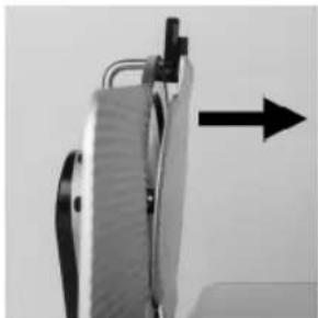
natural_image
Close-up of a mechanical device with a black arrow pointing upward (no visible text or symbols)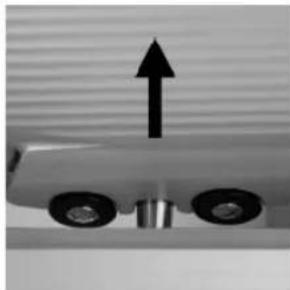
natural_image
Mechanical component with two wheels and an upward arrow, no visible text or symbolsnatural_image
Close-up of a mechanical gear assembly with two arrows pointing to specific components (no visible text or symbols)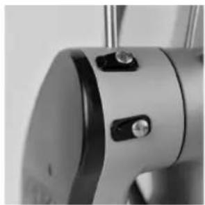
natural_image
Close-up of a metallic mechanical component with adjustment knobs and a circular base (no visible text or symbols)natural_image
Close-up of a mechanical device with lever and clamping mechanism (no visible text or symbols)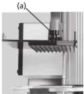
natural_image
Mechanical assembly diagram showing a bracket and mounting bracket (no text or symbols visible)natural_image
Close-up of a mechanical component with textured surface and labeled point (b), no readable text or symbols present.
natural_image
Close-up of a transparent plastic panel with a clip and handle, no visible text or symbolsGRAEF.
6.5 Maschine reinigen
natural_image
Close-up of a metallic chair handle with a grid-patterned cloth (no text or symbols visible)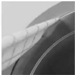
natural_image
Close-up of a car wheel rim with visible mesh pattern (no text or symbols)natural_image
Close-up of a hand pressing down on a surface with a black arrow pointing to the left side (no text or symbols visible)
natural_image
Hand cleaning a kitchen appliance with a hand holding a bowl and a bag, showing a black arrow indicating direction (no text or symbols visible)natural_image
Close-up of a vintage flatbed grater with a black handle and control panel, showing mechanical components (no text or symbols visible)
natural_image
Exterior view of a modern kitchen appliance with control panel and door (no visible text or symbols)
natural_image
Close-up of a computer monitor with a black downward arrow pointing to its screen (no text or symbols visible)natural_image
Three-panel technical illustration showing mechanical components with arrows indicating assembly or alignment (no text or symbols present)GRAEF.
7 Wartung
natural_image
Close-up of a mechanical component with an arrow pointing to a section (no visible text or symbols)
natural_image
Close-up of a mechanical clamp or bracket with arrows pointing to features (no visible text or symbols)8 Messer schärfen
natural_image
Close-up of a mechanical component with a black arrow pointing to a section labeled (1), no visible text or symbols beyond the label.
natural_image
Close-up of a mechanical component with a circular dial and a black arrow pointing to a small component (no visible text or symbols)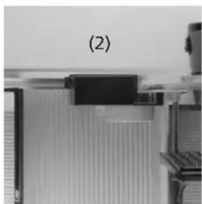
natural_image
Close-up of a mechanical component with no visible text or symbols
8.4 Messer schärfen
natural_image
Close-up of a mechanical component with a black arrow pointing to a circular feature (no visible text or symbols)GRAEF.
8.5 Grat prüfen
natural_image
Close-up of a metallic surface with a white diagonal stripe and a black arrow pointing to a seam or edge (no text or symbols)8.6 Messer abziehen
natural_image
Close-up of a mechanical device with a circular component and an arrow pointing to a button (no visible text or symbols)Typ: Concept 25, Concept 30
Typ: Concept 25, Concept 30
Typ: Concept 25, Concept 30
2 Application and description of the machine 35
2.1 Intended use
2.2 Description
2.3 Component designation
2.4 Variants and technical data
3 Safety 38
3.1 Introduction
3.2 General sources of danger
3.3 Work place
3.4 Authorised operators
3.5 Working clothes
3.6 Behaviour in case of emergency
3.7 Checking the protection device
4 Transport and installation 41
4.1 Transport
4.2 Requirements on the installation location
4.3 Connecting
4.4 Checking the machine
5 Operating 42
5.1 Prior to commissioning
5.2 Cutting
5.3 Cutting remainders
5.4 After cutting
6 Cleaning 44
6.1 Cleaning instructions
6.2 Cleaning agents
6.3 Cleaning schedule
6.4 Disassembly for cleaning
6.4.1 Folding down the slide
6.4.2 Removing the knife cover
6.4.3 Removing the blade scraper
6.4.4 Removing the top plate
6.5 Cleaning the machine
6.5.1 Cleaning the knife and knife ring
6.5.2 Cleaning the stop plate
6.5.3 Cleaning the slide
6.6 Assembly after cleaning
GRAEF.
7 Maintenance 51
7.1 Greasing / oiling
8 Sharpen blade 51
8.1 Description of the knife sharpener
8.2 Switch on machine
8.3 Putting on the blade sharpener
8.4 Sharpen blade
8.5 Checking the burr
8.6 Removing the blade
8.7 Removing the blade sharpener
8.8 Replacing blade
9 Miscellaneous 54
9.1 Frequent sources of error
9.2 Ordering spare parts
9.3 Warranty
9.4 Disposal of the cold-meat slicing machine
1 Introduction
This operating manual provides information about using the machine as well as potential hazards. Therefore please read this operating manual carefully.
Due to continuous further development, please note that pictorial representations might deviate from your cutting machine Concept.
Please keep this manual always in close proximity to your machine. It is a key component of the machine.
All persons who deal with installing, operating, maintaining and repairing the machine, must:
- be at least 14 years old,
- be trained and instructed for their activity,
- pay close attention to this operating manual.
In this operating manual, the following symbols and signal words are used:
DANGER | Indicates a potentially dangerous situation.In case of non-observation of this notice, severe and even life-threatening injuries can occur. |
WARNING | Indicates a dangerous situation.In case of non-observation of this warning, severe injuries and/or serious material damage can occur. |
CAUTION | Indicates a potentially dangerous situation.In case of non-observation of this warning message, minor injuries or material damage can occur. |
IMPORTANT! | Indicates application tips and other especially important information. |
2 Application and description of the machine
2.1 Intended use
The cold-meat slicing machine Concept has been designed as a working tool for the commercial sector. Its operation may be carried out only by instructed qualified personnel who are beyond 14 years of age.
The Concept is exclusively intended for cuttable foodstuffs such as: sausages, meat rolls, fish, ham and cheese.
The following must not be cut:
- Non-food articles
- Frozen cutting material
- Cutting material with bones or metal clips
The Concept machine has been designed for the use in kitchen areas and is not suitable for wet rooms or industrial environments. The machine must not be operated in an explosive atmosphere
Arbitrary modifications and changes to the machine are forbidden due to safety reasons.
The operating, maintenance and servicing instructions described in this operating manual must be observed. Repairs and blade changes have to be carried out by trained qualified personnel (please contact the authorised GRAEF SERVICE).
The machine has been designed for continuous operation.
2.2 Description
The Concept line is characterised by its slim design with large cutting material dimensions and good cleaning capabilities. The blade sizes range between 250 and 300 .
The hybrid drive ensures high cutting forces at lowest possible heating.
All materials getting in touch with foodstuffs are made of aluminium or special plastics, all of which fulfil the current hygiene regulations.
Slide grooves on the blade cover, stop plate and slide facilitate the cutting material feed.
The machine is equipped with a restart protection in case of power interruption.
The slide can be swivelled by 90^ for cleaning. To do so, the stop plate must b completely closed (below zero position).
The machine stands on suction feet ensuring a firm and safe stand
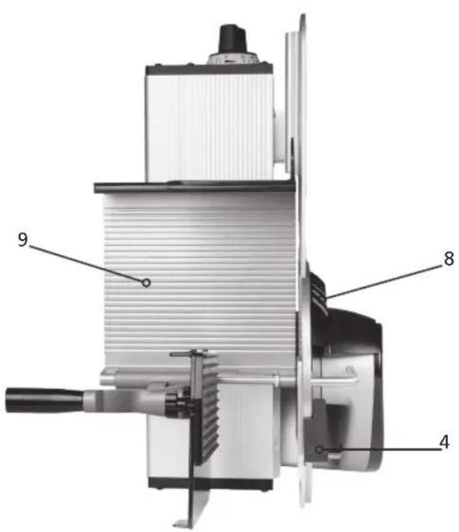
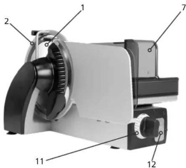
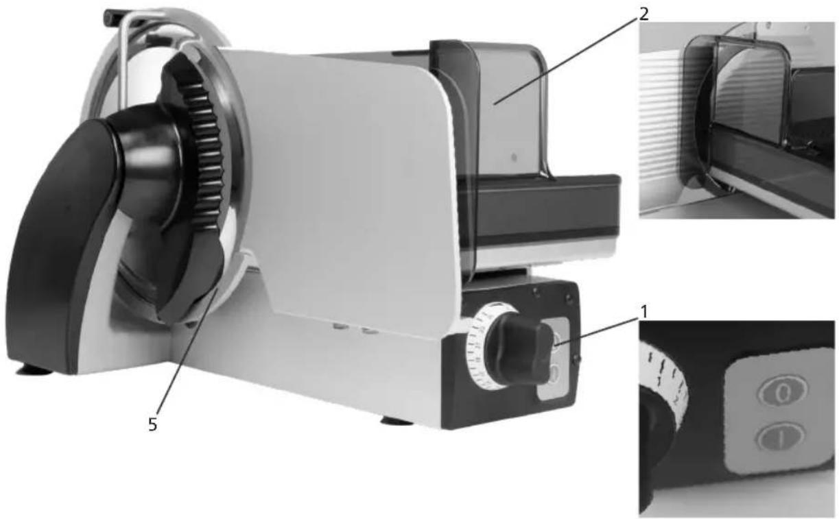
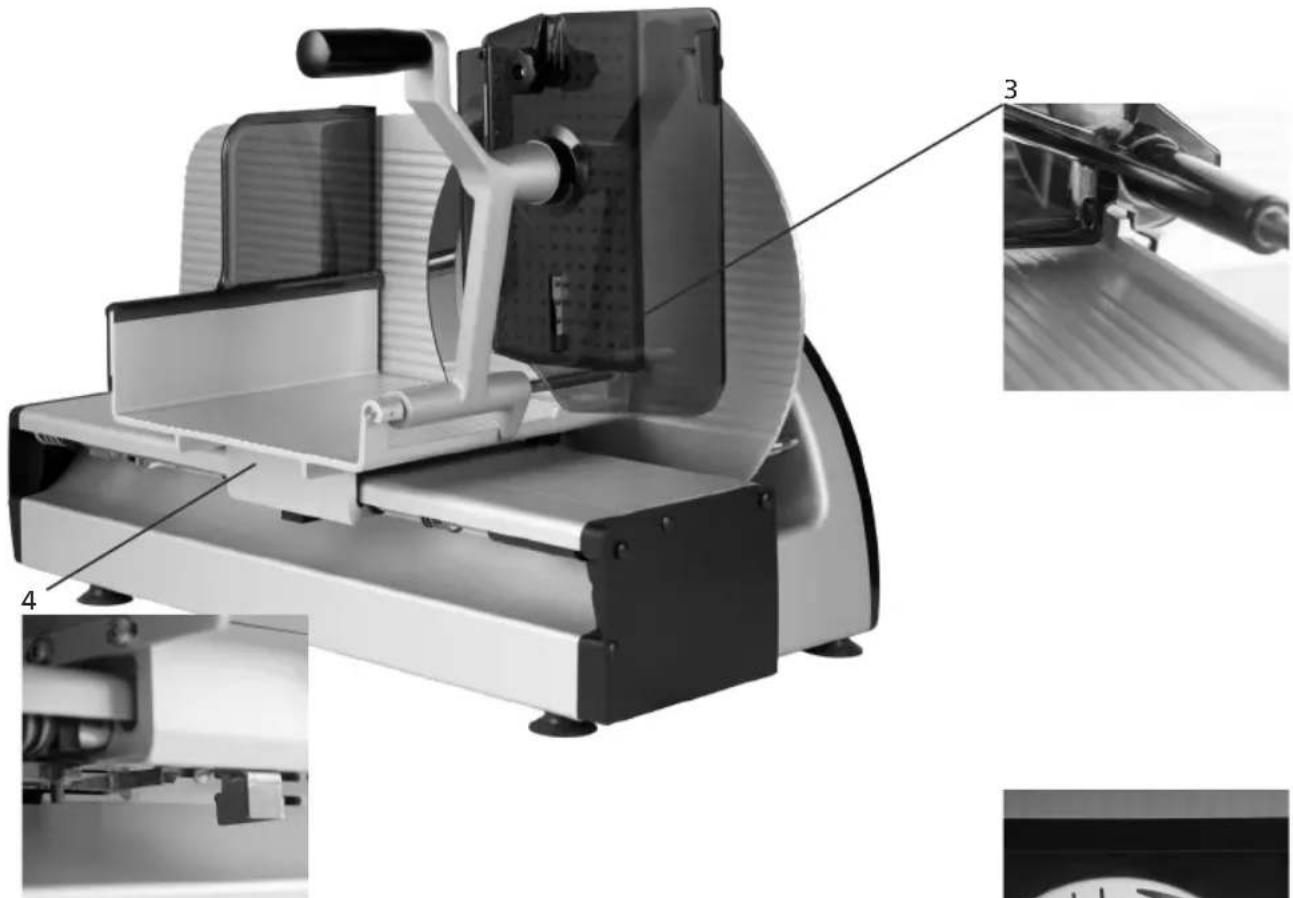
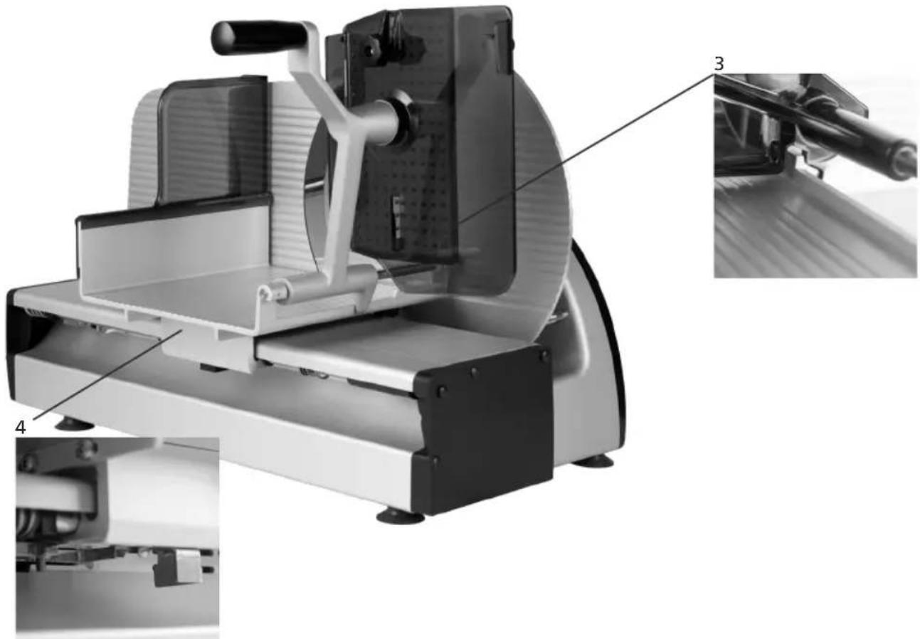
2.3 Component designation
| 1 Blade |
| 2Blade protecting ring |
| 3Blade cover |
| 4Blade cover handle |
| 5End-piece holder with protective plate |
| 6Top plate |
| 7Finger protection |
| 8Scraper |
| 9Carriage |
| 10Stop plate |
| 11Setting of cutting thickness |
| 12On/off switch with lamp |
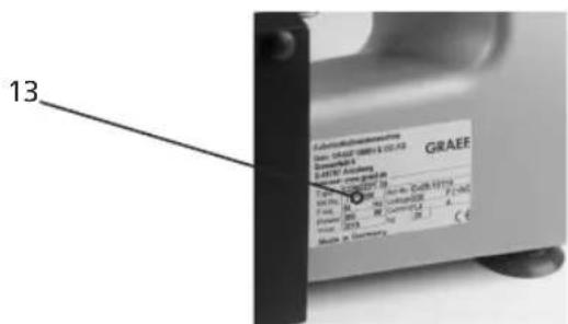
| 13Type plate |


2.4 Variants and technical data
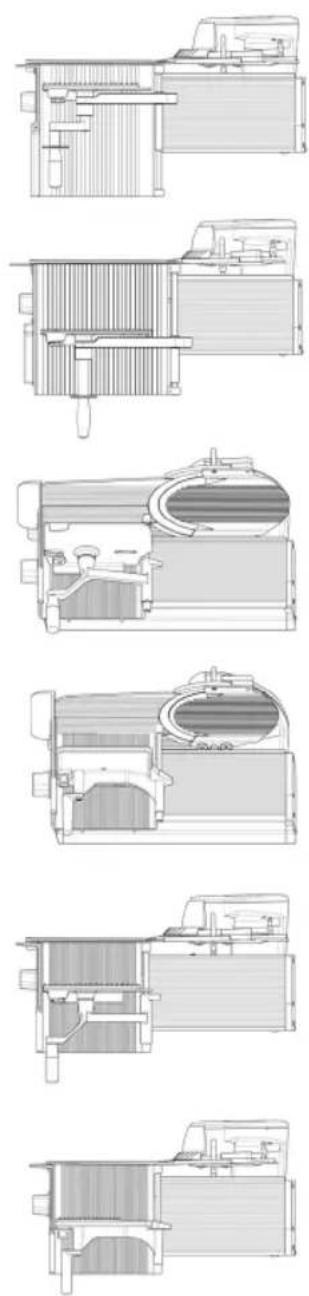
| CO25 CO30 | CO25S CO30S CO25L CO30F | |||||
| Design vertical vertical slanting | slanting vertical vertical | |||||
| Dimensions in mm (L x W x H) | 605 x 350 x 376 | 630 x 360 x 402 | 605 x 401 x 435 | 630 x 413 x 445 | 655 x 405 x 376 | 655 x 410 x 402 |
| Work room in mm (L x W x H) | 740 x 575 x 470 | 760 x 575 x 475 740 | x 530 x 590 760 | x 550 x 615 800 x | x 575 x 550 843 x 575 | x 520 |
| Floor space in mm (L x W) | 470 x 315 | 495 x 315 | 510 x 220 | 535 x 220 | 520 x 315 | 520 x 315 |
| Weight in kg | 20.1 kg | 21.6 kg | 25.3 kg | 27.1 kg | 23.6 kg | 24.3 kg |
| Blade diameter in mm | ∅250 | ∅300 | ∅250 | ∅300 | ∅250 | ∅300 |
| Blade speed in rev/min | 190 | 190 | 190 | 190 | 190 | 190 |
| Cutting size in mm (L x H) | 230 x 180 | 230 x 198 | 230 x 180 | 230 x 198 | 300 x 180 | 260 x 200 |
| Slide length in mm (L) | 250 | 250 | 250 | 250 | 300 | 300 |
| max. spacing of end-piece holder to the blade mm (L) | 130 | 100 | 130 | 100 | 160 | 135 |
| Power consumption, current, Voltage, frequency | See the type plate on the machine | |||||
| Protection class | IP33 | |||||
| Sound pressure level according to EN ISO 11204 at idling speed | < 69 dB (A) | |||||
| Vibration to which the hand /arm system is exposed | <2.5 m/s2 | |||||
3 Safety
3.1 Introduction
The cold-meat slicing machines are equipped with protective devices. Incorrect operation or misuse of the system, however, pose hazards for:
- the health,
- the machine,
- other material assets of the operating company.
All persons who deal with installing, operating, maintaining and repairing the machine, must be sufficiently trained. Plan regular repetitions of training sessions.
3.2 General sources of danger
DANGER | With a blade standing still or rotating, there exists a hazard of cutting or cutting off. When the machine is not in operation, the stop plate must always be closed in zero position. |
DANGER | The machine runs with a mains voltage of 230 V and thus must not be opened. The protective grounding system must absolutely be connected, because otherwise it may cause severe electrical shocks. |
DANGER | Attention: Magnetic and electromagnetic fields!Before persons with active implants (heat pacemakers etc.)stay in the vicinity of the machine or operate it, an individual risk assessment must be carried out on site jointly with skilled persons, the company doctor and a cardiologist, if necessary. |
WARNING | When tilting the slide, a hand can be squeezed.Therefore keep the hand which is not used away from the machine |
CAUTION | In the area of the end-piece holder, there is a risk of injury due to the tips and the end-piece holder falling downduring the insertion process. |
CAUTION | When mounting dismounted components for cleaning. |
GRAEF.
3.3 Work place
Operate the machine only when standing upright and safe.
Stand in front of the machine with a view to the ON/OFF button and the adjusting knob.
Always keep your workplace clean and clearly structured.
The machine must be set up on a firm and stable support
that withstands the weight stated in point 2.4 of the table and slight vibration.
3.4 Authorised operators
With the cold-meat slicing machine, only persons are allowed to work who:
- have read and understood the operating manual,
- have been trained in the operation by the operating company,
- have been informed about the dangers coming from the machine and the hygiene regulations,
- are over 14 years of age.
Repeat the training as required.
The machine may be maintained and repaired only by trained specialist personnel only (mechanic, electrician). In your operation, take measures preventing unauthorised persons from using, cleaning or maintaining the machine.
3.5 Working clothes
Wear close-fitting clothes when operating the machine. Also observe the hygiene regulations.
During cleaning and maintenance work on the blade, wear protective gloves with pulse protection.
During transport of the machine, always wear shoes with a steel cap.
3.6 Behaviour in case of emergency
In case of emergency, immediately press the OFF button.
3.7 Checking the protection device
- Daily before starting work,
- After every maintenance or repair.
Check for required state and function.
Have defects removed by specialist personnel.
It is forbidden to remove, change or disable protective devices.
| POS Setup Function | |
| 1 OFF button Immediate shutdown | |
| 2 Finger protection Avoids accidental access to | the front side of the blade with the thumb/ fingers. |
| 3 Positively driven end-piece holder Forces the | use with small pieces of cutting materials, e.g. leftover pieces, and thus avoids injuries to the fingers of the hand |
| 4 Locking of the stop plate The slide can only be | tilted if the stop plate has been fully closed (below-zero-position) and the blade edge is thus covered. |
| 5 Blade protecting ring Prevents accidental access to the edge of the blade | |
| 6 Switch-on protection No automatic start of the machine following an interruption of power supply, e.g. “power failure”. | |
natural_image
Technical illustration of a digital water heater with labeled components (no text or symbols beyond labels)GRAEF.

natural_image
Technical illustration of a mechanical device with labeled parts (3, 4), showing internal components and assembly lines (no readable text or symbols)4 Transport and installation
4.1 Transporting
Depending on the respective type, the cold-meat slicing machines have a weight of more the 20 kg
(see Table 2.4) and should be carried by 2 persons.
For long transports within the business, use suitable transport carriages.
Prior to transport, set the cut thickness to below "0"
by turning the adjusting knob up to the end stop.
Push the slide completely to the front and fix it sufficiently using adhesive tape.

4.2 Requirements on the installation location
The machine is designed for installation in kitchens and salesrooms.
- Ambient temperature for operation and storage: -10 to +40°C (+14 to +104 degrees Fahrenheit)
- Humidity protection class IP 33. High humidity or
condensation formation can result in damage to the machine.
- Relative humidity for operation and storage: 90% (condensation on the device is prohibited)
- For air convection in order to avoid inadmissible heating,
free air convection must be possible to form around the machine.
- Stipulated lighting 500 lux
The support must comply with the following requirements:
- Sufficiently robust, stable, level and horizontal.
- Sufficiently high for upright body posture during cutting.
- Space requirement according to the following list (see Table under point 2.4)
- Install the machine away from in-house traffic routes.
- Install the machine away from doors. Not in the pivoting range of an opening door, not in the access area of a door.
- With stainless tables, Resopal supports or similar materials, ensure that no grease residues are on the surface area.
4.3 Connecting
- Check that the local operating voltage corresponds to the specifications on the type plate. In case of deviations, you must not connect the machine.
- Electrical socket must comply with the national safety regulations (in Germany: VDE).
Technical data for power supply
– Power connection Single-phase alternating current, refer to rating plate
- The machine is designed according to protection class I and must be connected to a grounding conductor
– Permissible tolerance for voltage (static) normal
For 100 to 230V: +6% to -10% of nominal value
– Power frequency: 50 (60) Hz
Permissible tolerance for power frequency: +2% to -2% of nominal value
– Max. discharge current protective conductor: 3.5 mA
- Take measures on site if the grid is “unclean”, that means if thyristor controlled devices are used in the grid or grid asymmetries prevail that lead to voltage peaks.
- Lead the power cable away backwards in order to exclude stumbling over the cable.
4.4 Checking the machine
- Check the protective devices according to point 3.7.
- Check if the machine moves when it is switched on. Does it, or the support on which it stands, start moving away? If yes, provide a firmer support.
5 Operating
5.1 Prior to commissioning
Check the protective devices according to point 3.7.
DANGER

Rotating blade! Can cut off finger. Turn the adjusting knob for cut thickness setting clockwise to the end stop. Do not reach into the running blade.
GRAEF.
5.2 Cutting
Check the protective devices according to point 3.7.
Provided that the same operator touches the product and the controls, they must be cleaned between every usage!
- Pull back the slide completely.
- Lift the end-piece holder.
- Put the cutting material on the rear wall of the slide.
- Put the end-piece holder on top of the cutting material.
- Press the ON button. The machine is started.
- Set the cutting thickness by using the cutting thickness controller.
- For cutting, push the slide forward and backward while guiding the cutting material to the stop plate by slight pressure with the hand.
- At the end of the cutting process, completely close the stop plate and switch off the machine using the red "Off button".

natural_image
Close-up of a 3D printer printing a textured circular object into a tray (no visible text or symbols)
natural_image
Close-up of mechanical components with no visible text or symbols5.3 Cutting remainders
- Pull back the slide completely.
- Pull the holder for remainders outwards and lift it.
- Tied up end pieces: cut off the tied up end using the hand knife
- Insert the end piece with the original cut surface into the direction of the top plate on the slide back wall.
- Lower the end-piece holder and set it behind the end piece
- Switch on machine. The blade is rotating.
- Set the cutting thickness
- Using the end-piece holder, press the end piece by applying slight pressure against the stop plate and then push the slide forward and backward
- At the end of the cutting process, completely close the stop plate and switch off the machine using the red "Off button".
natural_image
Close-up of mechanical components or parts with no visible text or symbols
natural_image
Close-up of a corrugated metal structure with vertical bracing (no text or symbols visible)5.4 After cutting
- Basically, switch off machine
- Always close the stop plate completely so that the blade edge is fully covered.
6 Cleaning
Switch off the machine and additionally pull out the mains plug.
The machine must be cleaned thoroughly at least once a day.
DANGER | Rotating blade! Can cut off finger. Prior to cleaning, switch off the machine. Pull the mains plug. During cleaning work on the blade, wear protective gloves with pulse protection. |
IMPORTANT! | When cleaning, observe the prescribed order. Do not use scouring agents to clean the machine.They scratch the metallic surfaces and thus impair the hygiene.Never clean the machine using a steam or high-pressure cleaner!In the event of non-observation of the above points, any liability on our side will become void. |
6.1 Cleaning instructions
IMPORTANT! | You can easily clean removable parts with a dish-washing brush in the wash basin. Never clean parts in the dishwasher! |
CAUTION | Please carefully check all parts for correct and tight fit. Improperly fastened parts can get loose during operation and thus lead to machine damage, and in the worst case, also to injuries of the operator. |
When cleaning, observe the prescribed order. Do not use scouring agents to clean the machine.
They damage the surfaces and thus impair the hygiene.
Exclusively use the cleaning and hygiene agents approved by us in the prescribed thinning.
Do not use and aggressive cleaning and hygiene agents. For cleaning, do not use a high pressure cleaner. In the event of non-observation of the above points, any warranty claim will become void.
When using manual spraying devices, corresponding measures have to be taken so that there is no impairment to the environment.
The safety and product data sheets supplied with the cleaning and disinfection agents have to be observed.
Non-observation can lead to machine damages.
When using cleaning and disinfection agents which have not been approved by Graef, we will disclaim any warranty. Removable parts must not be cleaned in the dishwasher.
Installation of removed machine parts:
After cleaning, assemble the machine again in reverse order
GRAEF.
IMPORTANT! | After cleaning, neutralize aggressive cleaning and hygiene agents using sufficiently clear water, because otherwise corrosion, particularly on the blade screw connection, can occur. |
CAUTION | Please carefully check all parts for correct and tight fit. Improperly fastened parts can get loose during operation and thus lead to machine damage, and in the worst case, also to injuries of the operator. |
6.2 Cleaning agents
| P3 -sterile Ecolab | |
| P3 - alcodes Ecolab | |
| Maintenance oil: e.g. Graef service oil with H1 approval | GRAEF |
IMPORTANT! | When using cleaning agents which have not been approved by us, we will disclaim any warranty. Never clean removable parts in the dishwasher! Corresponding measures have to be taken so that there is no impairment to the environment! |
CAUTION | Absolutely observe the manufacturer specifications and instructions of the individual cleaning agents and oils |
6.3 Cleaning schedule
| Work steps Cleaning | agents Procedure Cleaning device Notes | |||
| 1. Preparatory measures | Close the cutting thickness adjustment.Pull the mains plug. | |||
| 2. Dismount the removable parts according to the operating manual | ||||
| 3. Coarse cleaning Manual | Removing the product residues with a Plastic scraper | Plastic scraper, also with removable parts. | Immediate beginning | |
| 4. Cleaning 2 % "P3 | sterile", for example. Acting time: approx. 15 min (also see product data sheet) | after thorough pre-flushing with (max. 40°) water; acting time approx. 20 minutes | Brush, tub, Cleaning cloth, Hand spraying device | all dismounted and stationary machine parts |
| 4. Disinfecting Additional measure | 0.5 -2% „P3-alcodes” Acting time: see product data sheet | manual spraying Do not exceed the acting time according to the product data sheet | One-way cleaning cloth, hand spraying device | additional protection, Spacing while spraying approx. 30 mm |
| 5. Rinsing Drinking water Temperature | max. 50 ° | One-way cleaning cloth | Remaining machine | |
| Hand spraying device | removed parts | |||
| Water hose removed | parts | |||
| 6. Checking visually for optical | cleanliness | |||
| 7. Drying rubbing dry | in the open air Let dry | One-way cleaning cloth | Machine, Put dismounted parts apart as possible | |
| 8. Maintaining Oils for the food-stuffs sector with H1 approval | Application by spraying or rubbing | One-way cleaning cloth | Prior to starting work, rinse all parts that get into contact with the cutting material | |
| 9. Mounting mounting takes | place in reverse order to dismounting (Operating manual) | Personnel must have clean and disinfected hands | ||
| 10. Precautionary measures | Cover the machine when cleaning the environment with a spraying device | |||
GRAEF.
| IMPORTANT! | The statements refer to single-shift operation.The safety and product data sheets supplied with the cleaning and disinfection agents have to be observed. |
6.4 Disassembly for cleaning
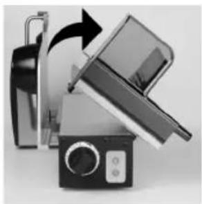
6.4.1 Folding down the slide
- Completely close the stop plate.
- Using some drive, pull the slide against the spring pressure completely back and dump it towards the right side in one movement.
| IMPORTANT! | The slide can be dumped only if the cutting thickness adjustment has been turned clockwise to the end stop and the stop plate is thus completely closed. |
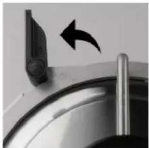
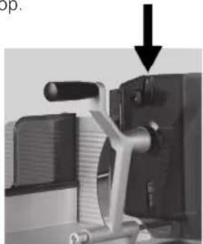
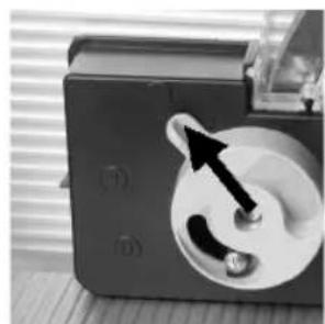
6.4.2 Removing the knife cover
- Put on cut-resistant protective gloves.
- Turn the black handle of the blade cover upward.
- Loosen the blade cover at the top.
- Then pull the blade cover upwards and then remove it from the machine.
natural_image
Close-up of a kitchen sink with a black arrow pointing to the outlet (no text or symbols visible)
natural_image
Close-up of a mechanical device with a black arrow pointing upward (no visible text or symbols)
natural_image
Close-up of a mechanical component with two wheels and an upward arrow, no visible text or symbols6.4.3 Removing the blade scraper
- Pull out the blade scraper leftwards (dovetail guides).
- To do so, reach into the provided finger recesses, as shown in the figure.
natural_image
Close-up of a mechanical gear assembly with directional arrows indicating motion (no text or symbols)
natural_image
Close-up of a metallic mechanical component with adjustment knobs and a circular base (no visible text or symbols)6.4.4 Removing the top plate
- Preliminarily, swivel up the remainder holder.
- CO30, 30S, 30 F, CO25L: For some turns, loosen the black knurled nut (a).
- Pull the plate upward and swivel the lower retaining pin out of the elongated hole
natural_image
Close-up of a mechanical device with lever and clamping mechanism (no visible text or symbols)
natural_image
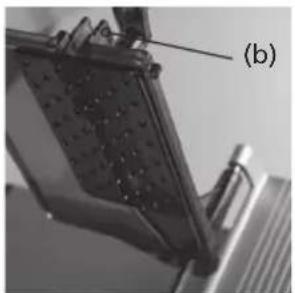
Mechanical assembly diagram showing a bracket and mounting bracket (no text or symbols visible)- CO25, 25S: On the top plate, press the locking device (b) together and pull out the top plate upward
- Pull the plate upward and swivel the lower retaining pin out of the elongated hole
natural_image
Close-up of a mechanical component with textured surface and labeled point (b), no readable text or symbols present.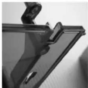
natural_image
Close-up of a transparent plastic panel with a clip and handle (no visible text or symbols)GRAEF.
6.5 Cleaning the machine
Clean removable and non-removable parts according to point 6
DANGER | Danger of injury! Wear safety gloves! |
IMPORTANT! | Do not put the parts on top of each other! Risk of damage! |
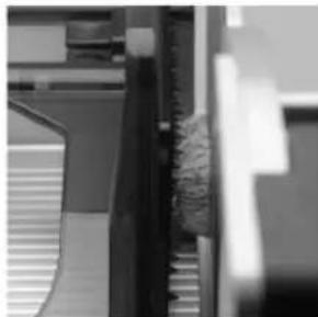
6.5.1 Cleaning the knife and knife ring
DANGER | Sharp blade! Only clean them when the slide has been tilted and the stop plate is thus closed. Cleaning movements always only from the knife centre outward to the blade edge. |
- From the front, insert a moistened cleaning cloth between the blade and the knife protecting ring.
- With your hands, pull through the cleaning cloth once or twice along the knife protecting ring.
- Press a wet cloth against the knife surface and slowly wipe off from the middle outwards.
- Clean the knife's rear side equally.
- Using a dry cloth, then dry off the knife in the same way.

natural_image
Close-up of a metallic stand with a grid-patterned cloth (no text or symbols visible)
natural_image
Close-up of a car wheel rim with visible tire tracks and side panels (no text or symbols)6.5.2 Cleaning the stop plate
- Press a wet cloth against the stop plate and slowly wipe off away from the knife. (see Fig.)
- Clean the back side of the stop plate in the same way.
- Clean the gap between stop plate and knife in the same way as with the gap between knife ring and knife. (see above)
- Using a dry cloth, then dry off the stop plate in the same way.
natural_image
Close-up of a hand pressing down on a surface with a black arrow pointing to the left side (no text or symbols visible)
natural_image
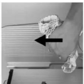
Hand cleaning a kitchen appliance with a hand holding a cloth and a black arrow indicating direction (no text or symbols visible)6.5.3 Cleaning the slide
- Tilt the slide for cleaning
- Roughly clean the upper side of the slide from cutting material remainders.
- Then wipe off the slide using a damp cloth.
natural_image
Close-up of a vintage flatbed grater with a black handle and control panel, showing mechanical components and a rotating arrow (no text or symbols visible)
natural_image
Exterior view of a modern office building (no signage)
natural_image
Close-up of a computer monitor with a black downward arrow pointing to its screen (no text or symbols visible)6.6 Assembly after cleaning
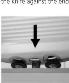
- Put the knife cover on the provided receptacles on the knife ring and position the upper borehole toward the upper screw on the knife ring.
Push the tension lever down.
- Insert the top plate into the end-piece holder.
- Swivel the slide back into the working position.
- From the left side, insert the blade scraper into the dovetail guide and carefully press it into the direction of the knife against the end stop.
natural_image
Mechanical device with a black arrow pointing to a component, no visible text or symbols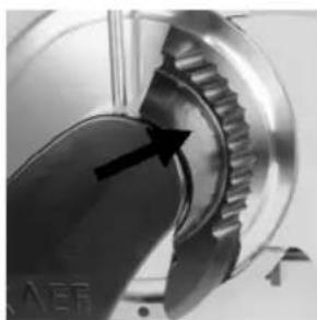
natural_image
Close-up of a mechanical gear component with an arrow pointing to a specific part (no visible text or symbols)GRAEF.
7 Maintenance
7.1 Greasing / oiling
DANGER | Rotating blade! Can cut off finger.Switch off the machine before maintenance. |
IMPORTANT! | For lubrication, use exclusively oils which have been approved by us. |
Using the Graef service oil H1, lubricate the following positions with 1-2 drops each as required, but at least once per week.
As required, apply a bit of oil to:
- The end-piece holder bar (always if it is hard to slide parts / after cleaning)
- The slide rail (always if it is hard to slide parts / after cleaning)
natural_image
Close-up of a mechanical component with an arrow pointing to a section, no visible text or symbols
natural_image
Close-up of mechanical components with arrows indicating direction (no visible text or symbols)8 Sharpen blade
Keep the knife sharpener that came with the machine in the vicinity of the machine. The knife may be exclusively sharpened with the knife sharpener that came with the machine.
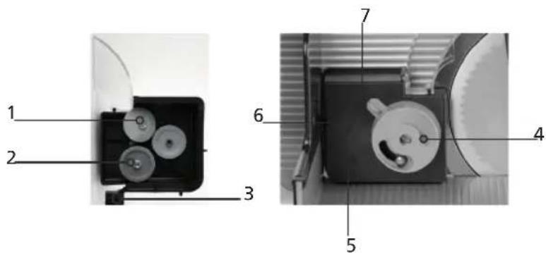
8.1 Description of the knife sharpener
Interior view
- Sharpening stone (1)
- Whetstone (2)
- Stop lug (3)
Exterior view
- Adjusting knob (4)
- Touchdown position "0" (5)
- Sharpening position „1" (6)
- Pull-off position "2" (7)
WARNING | Rotating blade! Can cut off finger. Sharpen the blade exclusively using the knife sharpener that came with the machine (cf. the serial number of the sharpener and machine!).The knife may only be sharpened by qualified and trained personnel. |
8.2 Preparing the machine
| IMPORTANT! | The knife sharpener may be used for this machine only.Before the grinding process, clean the knife of the cold-meat slicing machine thoroughly from grease and cutting remnants (Chapter 7), because otherwise the grindstones will clog and sharpening will be heavily affected. |
Remove all removable parts from the machine:
- Blade cover
- Scraper
- Top plate
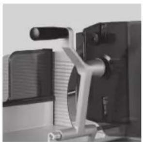
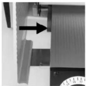
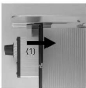
8.3 Putting on the blade sharpener
- Set the stop plate to "15 mm" cutting thickness.
- Move the slide to the middle position. (1)
- Using the adjusting knob, set the knife sharpener to position "0".
- Put the knife sharpener on the slide, as shown in the picture. (2)
- Slide it towards the blade until the lower stop lug of the sharpener rests against the knife ring. (3)
- Carefully close the stop plate so that the sharpener is clamped between the slide and stop plate
natural_image
Close-up of a mechanical component with a black arrow pointing to a section labeled (1), no visible text or symbols beyond the label.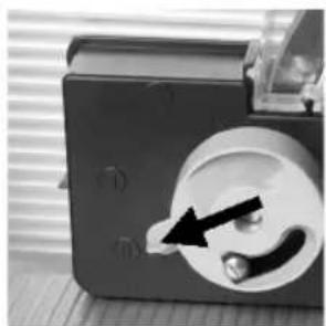
natural_image
Close-up of a mechanical device with a circular component and a black arrow pointing to a button (no visible text or symbols)
natural_image
Close-up of a mechanical component with a labeled section (2), showing no visible text or symbols.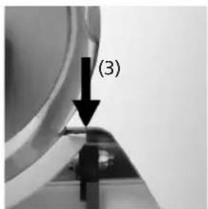
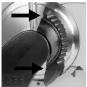
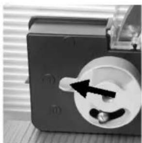
8.4 Sharpen blade
- Switch on the machine using the green ON button.
- Turn the rotary knob to grinding position "1".
- The grinding process starts.
- The grinding duration complies with the state of the knife.
natural_image
Close-up of a mechanical component with a circular dial and a black arrow pointing to a small knob (no visible text or symbols)GRAEF.
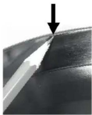
8.5 Checking the burr
- Grind until a slight burr occurs.
- Switch off the machine using the red OFF button.
-
Slide a sharp pencil slowly from the knife cover to the edge of the blade.
-
Do you feel a resistance on the edge of the blade?
- This is the burr that occurred during grinding.
- If no burr has occurred, keep grinding even further and check again.
natural_image
Close-up of a metallic surface with a white diagonal edge and a black arrow pointing downward (no text or symbols)8.6 Removing the blade
- If a burr has formed on the edge of the blade, turn the adjusting knob to pull-off position "2".
- Let the machine rotate some turns and switch off the device using the OFF button.
natural_image
Close-up of a mechanical device with a circular component and an arrow pointing to a knob (no visible text or symbols)8.7 Removing the knife sharpener
- Turn the adjusting knob of the knife sharpener to position "0".
- Open the stop plate and cautiously remove the sharpener upward.
- Close the stop plate completely.
- Clean the machine and knife from grinding dust.
8.8 Replacing blade
WARNING | Sharp blade! May cause severe cut injuries even at a standstill.The blade may be replaced by trained and qualified personnel only.Put on cut-resistant protective gloves. |
IMPORTANT! | The knife must be replaced if the distance between the edge of the blade and the blade protecting ring exceeds 6 mm. |
9 Miscellaneous
9.1 Frequent sources of error
| Error Cause Solution | ||
| Slide is difficult to move Slide guide | bar is dry Oil the slide guide bar - point 8.1 | |
| End-piece holder is difficult to move | End-piece holder bar is dry Oil the end-piece holder bar Item 8.1 | |
| Slide cannot be tilted Slide protection | on is blocked Close the stop plate completely | |
| Poor cut Blade is dull Sharpen blade | Item 8.4 | |
| poor sharpening result Grinding discs are greasy Replace the grinding discs | ||
| Blade cannot be sharpened Blade is | ground down beyond the admissible 5 mm | Replace the knife |
9.2 Ordering spare parts
When ordering spare parts, please indicate the following:
- Machine number
- Year of construction
- Type
- Operating voltage
- Part description
IMPORTANT! | Use genuine spare parts only from Graef. |
GRAEF.
9.3 Warranty
With this machine, you have purchased a recognised quality product of German production. We assume the manufacturer warranty for defects which are due to production or material defects.
However, we cannot accept any liability for the following damages:
- naturally occurring wear and tear
- Ignorance or non-observance of this operating manual
- Due to cleaning in a dishwasher
- Unauthorised installation of the machine in a non-appropriate area
-
Incorrect electrical installation on site (e.g. "unclean grid" of voltage peaks due to grid asymmetries)
-
Self-executed conversions/changes to the cutting machine and/or the accessories;
- Disabling, manipulating of protective devices on the cutting machine and/or the accessories
- Use of other spare parts and accessory parts which are not genuine parts from Graef
- If not using the original packaging during transport
9.4 Disposal of the cold-meat slicing machine
As a customer, please return the machine to the manufacturer or dealer for environmentally compatible recycling.
Graef Company and its dealers are willing to take back the machine free of charge.
Please get in touch with your dealer.
The applicability of this disposal regulation shall depend on the respective legal stipulation in each country.
Contenu


GRAEF.
GRAEF.

natural_image
Technical illustration of a mechanical device with labeled parts (3, 4), showing internal components and assembly lines (no readable text or symbols)natural_image
Close-up of a rotary dial with dual dials (21 and 23, 25) and a pointer at 0 (no text or symbols visible)natural_image
Close-up of a mechanical device with a circular component on a tray, no visible text or symbols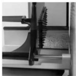
natural_image
Close-up of a mechanical component with a serrated edge and handle, no visible text or symbolsnatural_image
Close-up of mechanical components or parts, possibly a tool or bracket, with no visible text or symbols.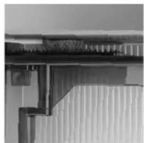
natural_image
Close-up of a corrugated metal structure with no visible text or symbolsnatural_image
Close-up of a mechanical component with an arrow indicating rotation (no visible text or symbols)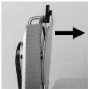
natural_image
Close-up of a mechanical device with a black arrow pointing upward (no visible text or symbols)
natural_image
Mechanical component with two wheels and an upward arrow, no visible text or symbolsnatural_image
Close-up of a mechanical gear assembly with directional arrows indicating motion (no text or symbols)
natural_image
Close-up of a metallic mechanical component with adjustment knobs and a circular base (no visible text or symbols)natural_image
Close-up of a mechanical device with lever and clamping mechanism (no visible text or symbols)
natural_image
Mechanical assembly diagram showing a bracket and mounting bracket (no text or symbols visible)natural_image
Close-up of a mechanical component with textured surface and labeled point (b), no readable text or symbols present.
natural_image
Close-up of a transparent plastic panel with a clip and handle, no visible text or symbolsGRAEF.
6.5 Nettoyage de la machine
natural_image
Close-up of a metallic chair handle with a white patterned sheet and black diagonal stripe (no text or symbols visible)
natural_image
Close-up of a car wheel rim with white mesh railings (no visible text or symbols)natural_image
Close-up of a hand pressing down on a surface with a black arrow pointing to the left side (no text or symbols visible)
natural_image
Hand cleaning a kitchen appliance with a hand holding a bowl and a bag, showing a black arrow indicating direction (no text or symbols visible)natural_image
Close-up of a vintage flatbed grater with a black handle and control panel, showing mechanical components (no text or symbols visible)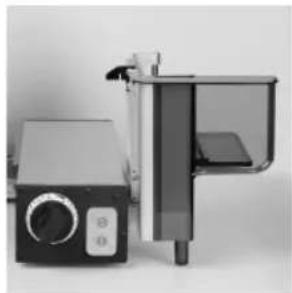
natural_image
Exterior view of a modern office building (no signage)
natural_image
Close-up of a computer monitor with a black downward arrow pointing to its screen (no visible text or symbols)natural_image
Close-up of a mechanical component with an arrow pointing to a section, no visible text or symbols
natural_image
Close-up of a mechanical clamp or bracket with two arrows pointing to specific features (no visible text or symbols)8 Aiguiser la lame
natural_image
Close-up of a mechanical component with a black arrow pointing to a section, labeled (1), showing no readable text or symbols.
natural_image
Close-up of a mechanical device with a circular component and a black arrow pointing to a small component (no visible text or symbols)
natural_image
Close-up of a mechanical component with layered structure, labeled (2), no visible text or symbols
8.4 Aiguiser la lame
natural_image
Close-up of a black electrical socket with a black arrow pointing to the socket (no visible text or symbols)GRAEF.
8.5 Vérifier bavure
natural_image
Close-up of a metallic surface with a white diagonal stripe and a black arrow pointing to a seam or edge (no text or symbols)natural_image
Close-up of a mechanical device with a circular component and an arrow pointing to a button (no visible text or symbols)
GRAEF.
GRAEF.
natural_image
Technical illustration of a mechanical device with labeled parts (3, 4), showing internal components and assembly lines (no readable text or symbols)natural_image
Close-up of a black industrial rotary dial with scale markings (no visible text or symbols)4.1 Transporte
natural_image
Close-up of a 3D printer printing a textured circular object into a tray (no visible text or symbols)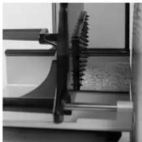
natural_image
Close-up of mechanical components with no visible text or symbolsnatural_image
Close-up of mechanical components or parts with no visible text or symbols
natural_image
Close-up of a corrugated metal structure with vertical bracing (no text or symbols visible)natural_image
Close-up of a mechanical component with an arrow indicating rotation (no visible text or symbols)
natural_image
Close-up of a mechanical device with a black arrow pointing upward (no visible text or symbols)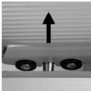
natural_image
Mechanical component with two wheels and an upward arrow, no visible text or symbolsnatural_image
Close-up of a mechanical gear assembly with directional arrows indicating motion (no text or symbols)
natural_image
Close-up of a metallic mechanical component with adjustment knobs and a circular base (no visible text or symbols)natural_image
Mechanical assembly diagram showing a presser and a clamping device (no text or symbols visible)natural_image
Close-up of a mechanical component with textured surface and labeled point (b), no readable text or symbols present.
natural_image
Close-up of a transparent plastic panel with a clip and handle (no visible text or symbols)GRAEF.
natural_image
Close-up of a metallic chair handle holding a white patterned cloth (no text or symbols visible)
natural_image
Close-up of a curved metallic object with a chain-link fence, possibly part of a vehicle or industrial structure (no visible text or symbols)natural_image
Close-up of a hand pressing down on a surface with a black arrow pointing to the left side (no text or symbols visible)
natural_image
Hand cleaning a kitchen appliance with a hand holding a cloth and a black arrow indicating direction (no text or symbols visible)6.5.3 Limpieza del carro
natural_image
Close-up of a vintage flatbed grater with a black handle and control panel, showing mechanical components (no text or symbols visible)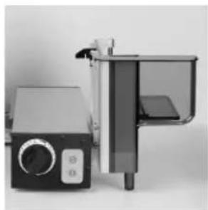
natural_image
Exterior view of a modern office building (no signage)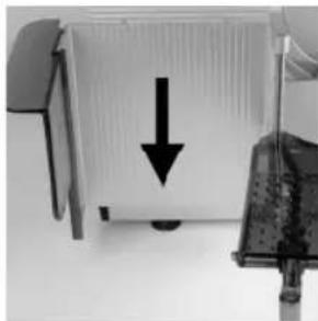
natural_image
Close-up of a computer monitor with a black downward arrow pointing to its screen (no visible text or symbols)natural_image
Three-panel technical illustration showing mechanical components with arrows indicating assembly or alignment (no text or symbols present)GRAEF.
7 Mantenimiento
7.1 Lubricación / engrase
natural_image
Close-up of a mechanical component with an arrow pointing to a section (no visible text or symbols)
natural_image
Close-up of a mechanical clamp or lever mechanism with arrows pointing to specific parts (no visible text or symbols)natural_image
Close-up of a mechanical component with a black arrow pointing to a section labeled (1), no visible text or symbols beyond the label.
natural_image
Close-up of a mechanical component with a black arrow pointing to a circular feature (no visible text or symbols)
natural_image
Close-up of a mechanical component with no visible text or symbols
natural_image
Close-up of a mechanical component with a circular socket and an arrow indicating a pin or insertion (no visible text or symbols)GRAEF.
natural_image
Close-up of a metallic surface with a black arrow pointing to a specific edge (no text or symbols visible)natural_image
Close-up of a mechanical device with a black arrow pointing to a circular component (no visible text or symbols)

GRAEF.

natural_image
Technical illustration of a mechanical device with labeled parts (3, 4), showing internal components and assembly lines (no readable text or symbols)natural_image
Close-up of a rotary dial with dual dials (21 and 23, 25) and a pointer at 0 (no text or symbols visible)natural_image
Close-up of a 3D printer printing a textured circular object into a tray (no visible text or symbols)
natural_image
Close-up of mechanical components with no visible text or symbolsnatural_image
Close-up of mechanical components or parts, possibly a valve or clamping device, with no visible text or symbols.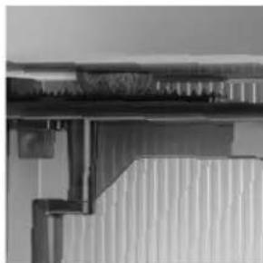
natural_image
Close-up of a corrugated metal structure with vertical bracing (no text or symbols visible)5.4 Na het snijden
natural_image
Close-up of a kitchen sink with a black arrow pointing to a cylindrical object on top (no text or symbols visible)
natural_image
Close-up of a mechanical device with a black arrow pointing upward (no visible text or symbols)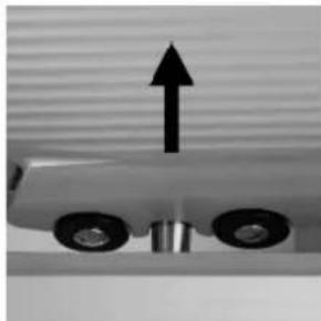
natural_image
Close-up of a mechanical component with two wheels and an upward arrow, no visible text or symbolsnatural_image
Close-up of a mechanical gear assembly with directional arrows indicating motion (no text or symbols)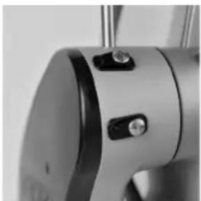
natural_image
Close-up of a metallic mechanical component with adjustment knobs and a circular base (no visible text or symbols)natural_image
Mechanical assembly diagram showing a presser and a clamping device (no text or symbols visible)natural_image
Close-up of a mechanical component with textured surface and labeled point (b), no readable text or symbols present.
natural_image
Close-up of a transparent plastic panel with a clip and handle (no visible text or symbols)GRAEF.
6.5 Machine schoonmaken
natural_image
Close-up of a medical or surgical sash with grid pattern, no visible text or symbols
natural_image
Close-up of a car's wheel rim and side panel, showing white plastic film (no text or symbols visible)natural_image
Close-up of a hand pressing down on a surface with a black arrow pointing to the left side (no text or symbols visible)
natural_image
Hand cleaning a kitchen appliance with a hand holding a cloth and a black arrow indicating direction (no text or symbols visible)6.5.3 Slede reinigen
natural_image
Close-up of a vintage flatbed grater with a black handle and control panel, showing mechanical components and a rotating arrow (no text or symbols visible)
natural_image
Exterior view of a modern office building (no signage)
natural_image
Close-up of a computer monitor with a black downward arrow pointing to its screen (no text or symbols visible)natural_image
Three-panel technical illustration showing mechanical components with arrows indicating assembly or alignment (no text or symbols present)GRAEF.
7 Servicebeurt
7.1 Smeren / oliën
natural_image
Close-up of a mechanical component with an arrow pointing to a textured surface (no visible text or symbols)
natural_image
Close-up of a mechanical clamp or bracket with arrows pointing to specific features (no visible text or symbols)8 Het mes slijpe
WAARSCHUWING
natural_image
Close-up of a mechanical component with a black arrow pointing to a section, labeled (1), showing no readable text or symbols.
natural_image
Close-up of a mechanical component with a circular dial and a black arrow pointing to a small component (no visible text or symbols)
natural_image
Close-up of a mechanical component with no visible text or symbols
8.4 Het mes slijpe
natural_image
Close-up of a black electrical socket with a black arrow pointing to the socket (no visible text or symbols)GRAEF.
8.5 Braam controleren
natural_image
Close-up of a curved surface with a black arrow pointing to a sharp edge (no text or symbols visible)8.6 Mes aftrekken
natural_image
Close-up of a mechanical device with a circular component and an arrow pointing to a button (no visible text or symbols)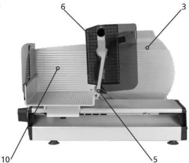

GRAEF.
natural_image
Technical illustration of a mechanical device with labeled parts (3, 4), showing internal components and assembly lines (no readable text or symbols)natural_image
Close-up of a rotary dial with dual dials (21 and 23, 25) and a pointer at 0 (no text or symbols visible)natural_image
Close-up of a 3D printer printing a textured circular object into a tray (no visible text or symbols)
natural_image
Close-up of mechanical components with no visible text or symbolsnatural_image
Close-up of mechanical components or parts, possibly a valve or clamping device, with no visible text or symbols.
natural_image
Close-up of a corrugated metal structure with vertical bracing (no text or symbols visible)5.4 Efter skæring
natural_image
Close-up of a kitchen sink with a black arrow pointing to the outlet (no text or symbols visible)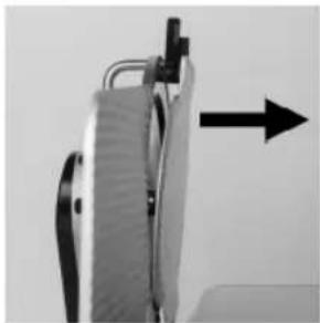
natural_image
Close-up of a mechanical device with a black arrow pointing to a component (no visible text or symbols)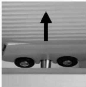
natural_image
Close-up of a mechanical component with two wheels and an upward arrow, no visible text or symbols6.4.3 Afmontering af oliering
natural_image
Close-up of a mechanical gear assembly with directional arrows indicating motion (no text or symbols)
natural_image
Close-up of a metallic mechanical component with adjustment knobs and a circular base (no visible text or symbols)natural_image
Close-up of a mechanical device with lever and clamped components (no visible text or symbols)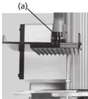
natural_image
Mechanical assembly diagram showing a clamping mechanism with labeled component (a), no readable text or symbols present.natural_image
Close-up of a mechanical component with textured surface and labeled point (b), no readable text or symbols present.
natural_image
Close-up of a transparent plastic panel with a clip and handle (no visible text or symbols)GRAEF.
natural_image
Close-up of a metallic chair handle with a grid-patterned cloth (no visible text or symbols)
natural_image
Close-up of a car wheel rim with visible mesh pattern (no text or symbols)natural_image
Close-up of a hand pressing down on a surface with a black arrow pointing to the left side (no text or symbols visible)
natural_image
Hand cleaning a kitchen appliance with a hand holding a cloth and a black arrow indicating direction (no text or symbols visible)6.5.3 Rengør slæde
natural_image
Close-up of a vintage flatbed grater with a black handle and control panel, showing mechanical components (no text or symbols visible)
natural_image
Exterior view of a modern kitchen appliance with control panel and door (no visible text or symbols)
natural_image
Close-up of a computer monitor with a black downward arrow pointing to its screen (no visible text or symbols)natural_image
Three-panel technical illustration showing mechanical components with arrows indicating assembly or alignment (no text or symbols present)GRAEF.
7 Vedligeholdelse
7.1 Smøring/olie
natural_image
Close-up of a mechanical component with an arrow pointing to a section (no visible text or symbols)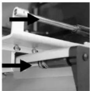
natural_image
Close-up of a mechanical clamp or bracket with arrows pointing to specific components (no visible text or symbols)8 Slibning af kniv
natural_image
Close-up of a mechanical component with a black arrow pointing to a section labeled (1), no visible text or symbols beyond the label.
natural_image
Close-up of a mechanical device with a black arrow pointing to a circular component (no visible text or symbols)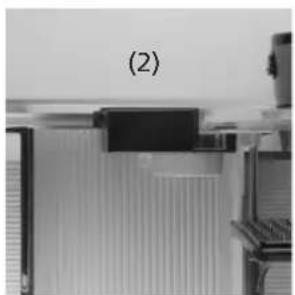
natural_image
Close-up of a mechanical component with no visible text or symbols