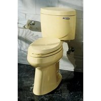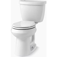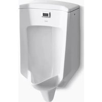
Bardon K-32590 - Toilet KOHLER - Free user manual and instructions
Find the device manual for free Bardon K-32590 KOHLER in PDF.


User questions about Bardon K-32590 KOHLER
0 question about this device. Answer the ones you know or ask your own.
Ask a new question about this device
Download the instructions for your Toilet in PDF format for free! Find your manual Bardon K-32590 - KOHLER and take your electronic device back in hand. On this page are published all the documents necessary for the use of your device. Bardon K-32590 by KOHLER.
USER MANUAL Bardon K-32590 KOHLER
Installation Instructions
Touchless Urinal
Record your model number:
Need help? Contact our Customer Care Center.
- USA/Canada: 1-800-4KOHLER (1-800-456-4537) Mexico: 001-800-456-4537
Hours of Operation: Monday-Friday 8:00 AM -5:00 PM (CT)
Languages Spoken: English, Spanish, and translation services are available.
• Service parts: kohler.com/serviceparts
• Care and cleaning: kohler.com/clean
• Patents: kohlercompany.com/patents
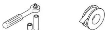
Tools and Materials

natural_image
Illustration of various mechanical tools including eyeglasses, screwdriver, wrench, and battery (no text or labels)5/8" Wrench 1/4" Socket
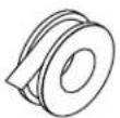
Thread Sealant Tape
Plus:
- Conventional woodworking tools and materials
• Hole Cutting Equipment
• Appropriate Screws - AA Batteries (4)

CAUTION: Risk of personal injury. Handle this product with care. Vitreous china can break or chip if the product is handled carelessly.
NOTE: Roughing-in dimensions remain the same when using the optional 3" outlet spud.
Unpack and inspect the product for damage. Return the product to the carton until installation.
Your product may appear different from the one illustrated. The installation procedure is the same.
Fixture dimensions are nominal and conform to tolerances in ASME Standard A112.19.2/CSA B45.1.
ADA compliant when the rim is mounted no higher than 17" (432 mm) from the finished floor.
Follow all local plumbing and building codes.
Turn OFF the water supplies.
1. Prepare the Site
text_image
Backer Board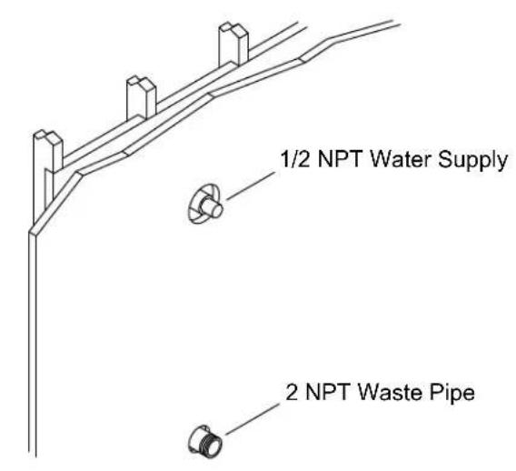
text_image
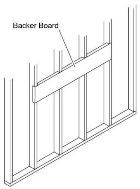
1/2 NPT Water Supply 2 NPT Waste Pipe☐ Install a backer board for additional support, if needed. Verify that the front of the backer board is installed flush with the studs.
☐ Install a 2 NPT waste pipe according to the Roughing-In Sheet.
☐ Install a 1/2 NPT water supply inlet according to the Roughing-In Sheet.
□ Install the shut-off valve.
2. Install the Wall Hangers
text_image
12" (305 mm) 19-9/16" (497 mm)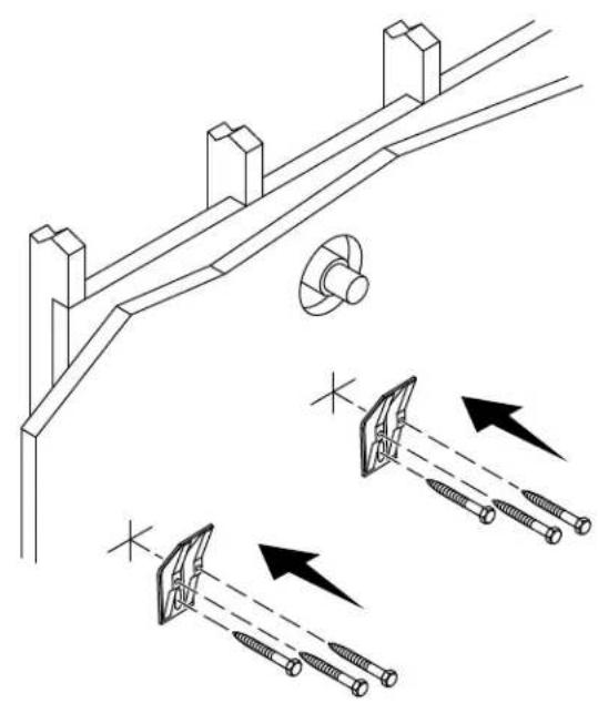
natural_image
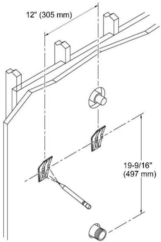
Technical illustration of a mechanical bracket with two screws and directional arrows indicating movement or force (no text or symbols)☐ Position the top holes of the wall hangers 19-9/16" (497 mm) above the center of the waste pipe.
☐ Position the center of the wall hangers 12" (305 mm) apart and mark each location for the screws.
□ Secure the wall hangers with appropriate screws (not provided).
3. Install the Urinal
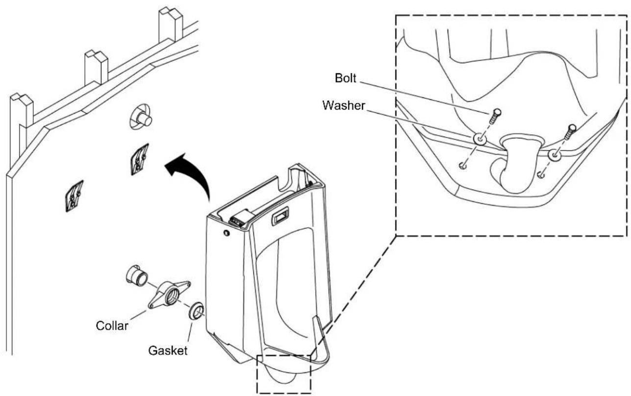
text_image
Bolt Washer Collar Gasket
CAUTION: Risk of personal injury. Handle this product with care. Vitreous china can break or chip if the product is handled carelessly.

CAUTION: Risk of product damage. Do not overtighten the bolts.
NOTE: Do not caulk the top surface of the urinal. Caulk may prevent the tank cover from seating properly.
□ Remove the collar and gasket from the urinal.
□ Apply thread sealant tape to the threads of the waste pipe.
☐ Install the collar to the waste pipe.
□ With the beveled surface of the gasket facing away from the collar, place the gasket onto the collar.
☐ Secure the urinal to the collar using the washers and bolts provided.
4. Install the Sensor
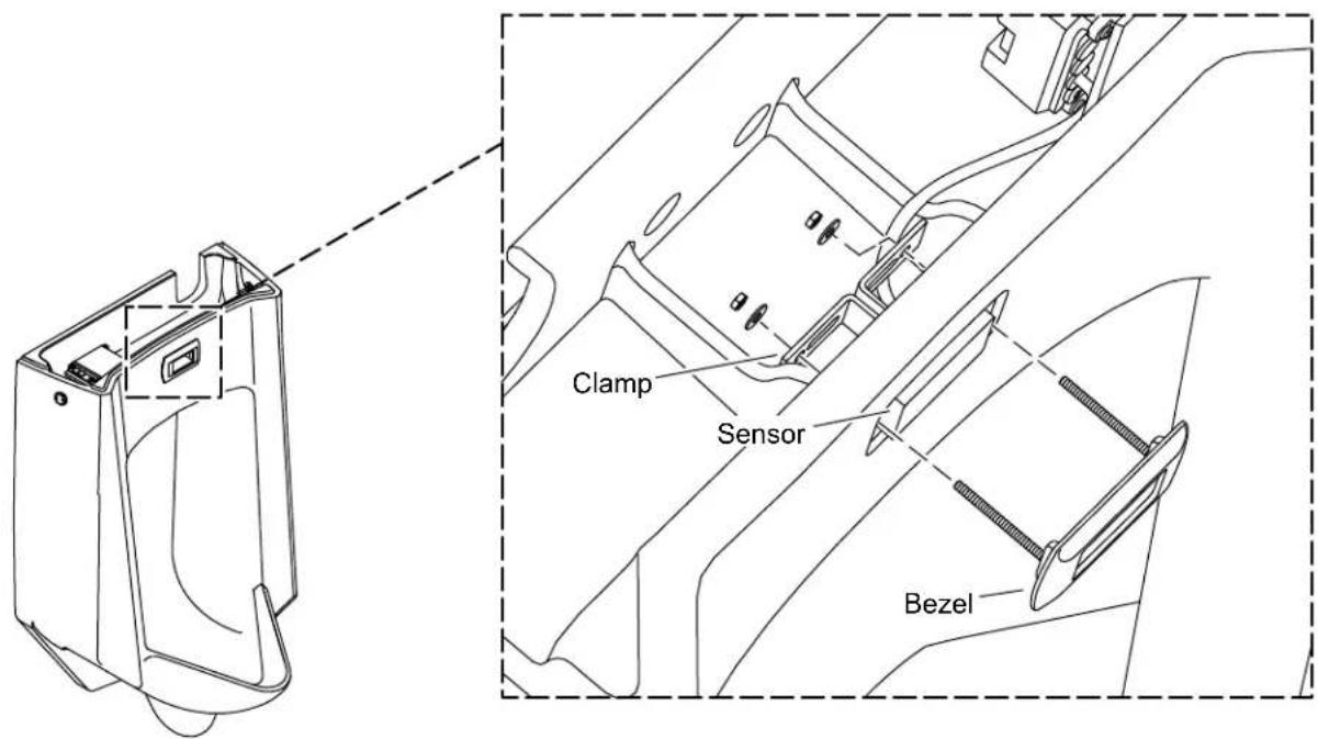
text_image
Clamp Sensor Bezel☐ Disassemble the bezel, clamps, nuts, and washers from the urinal.
□ Place the sensor in the urinal.
☐ Place the bezel over the sensor and align the two threaded studs through the holes of the clamps.
☐ Secure the clamps to the studs with two nuts and two washers.
☐ Tighten the nuts until bezel and clamps hold the sensor securely in the hole.
5. Install the Valve Assembly
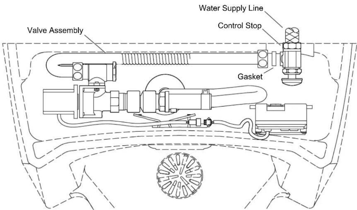
text_image
Valve Assembly Water Supply Line Control Stop GasketIMPORTANT! When disconnecting the control stop from the valve assembly, the gasket will fall out from the end of the valve assembly. Retain the gasket.
☐ Using thread sealant tape, wrap the end of the water supply line.
☐ Disconnect the control stop from the valve assembly.
□ Retain the gasket from the valve assembly.
□ Attach the control stop to the water supply line.
☐ Reinsert the gasket into the end of the valve assembly.
□ Reconnect the control stop to the valve assembly.
6. Test the Control Unit
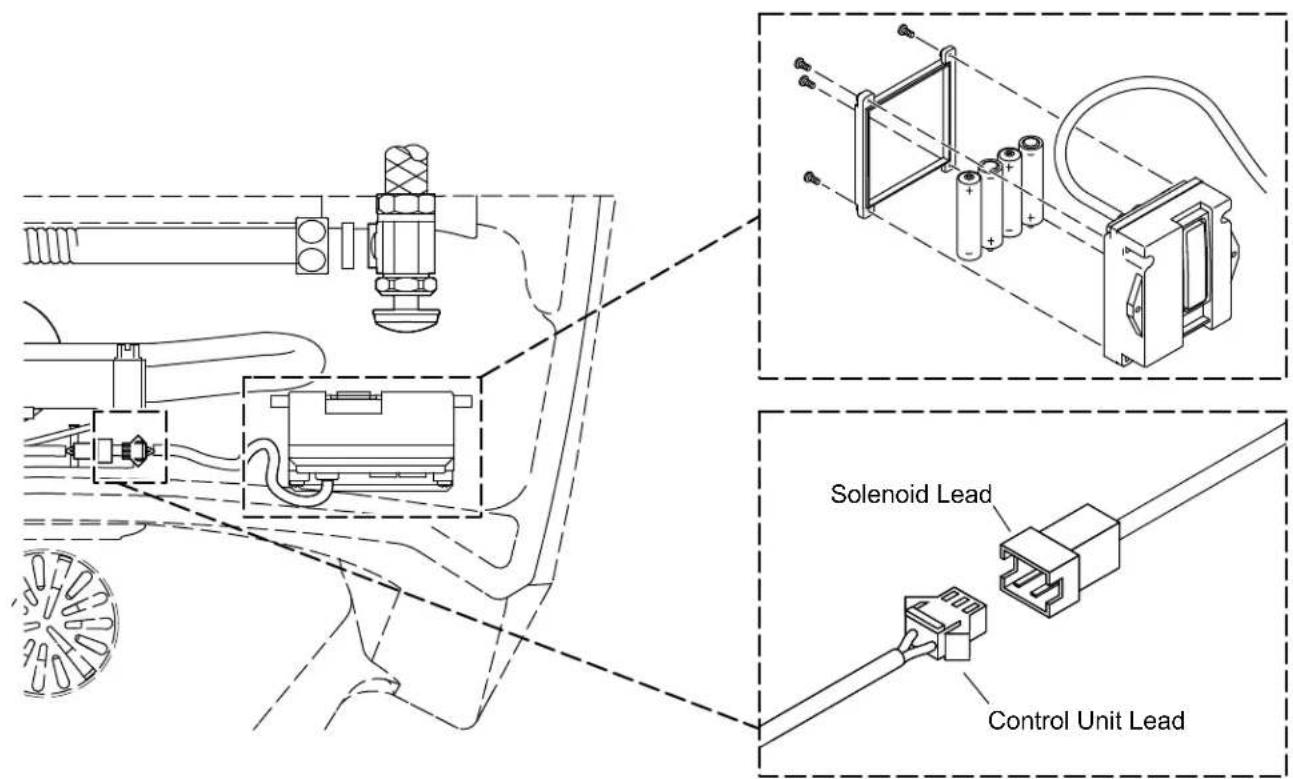
text_image
Solenoid Lead Control Unit LeadConnect
□ Remove the four screws from the cover of the battery compartment. Set the four screws and cover aside.
☐ Install four AA batteries (not provided) into the battery compartment.
☐ Reinstall the cover to the battery compartment.
☐ Plug the solenoid lead into the control unit lead. Wait 10 minutes before proceeding.
Test
□ Stand in front of the urinal for at least 10 seconds.
☐ Step aside from the urinal. The valve will flush after a slight delay.
Check
☐ Check the entire installation for leaks. Repair as needed.
☐ If cover locks will not be installed, place the cover on the tank. If cover locks will be installed, proceed to the "Install the Locks" section.
text_image
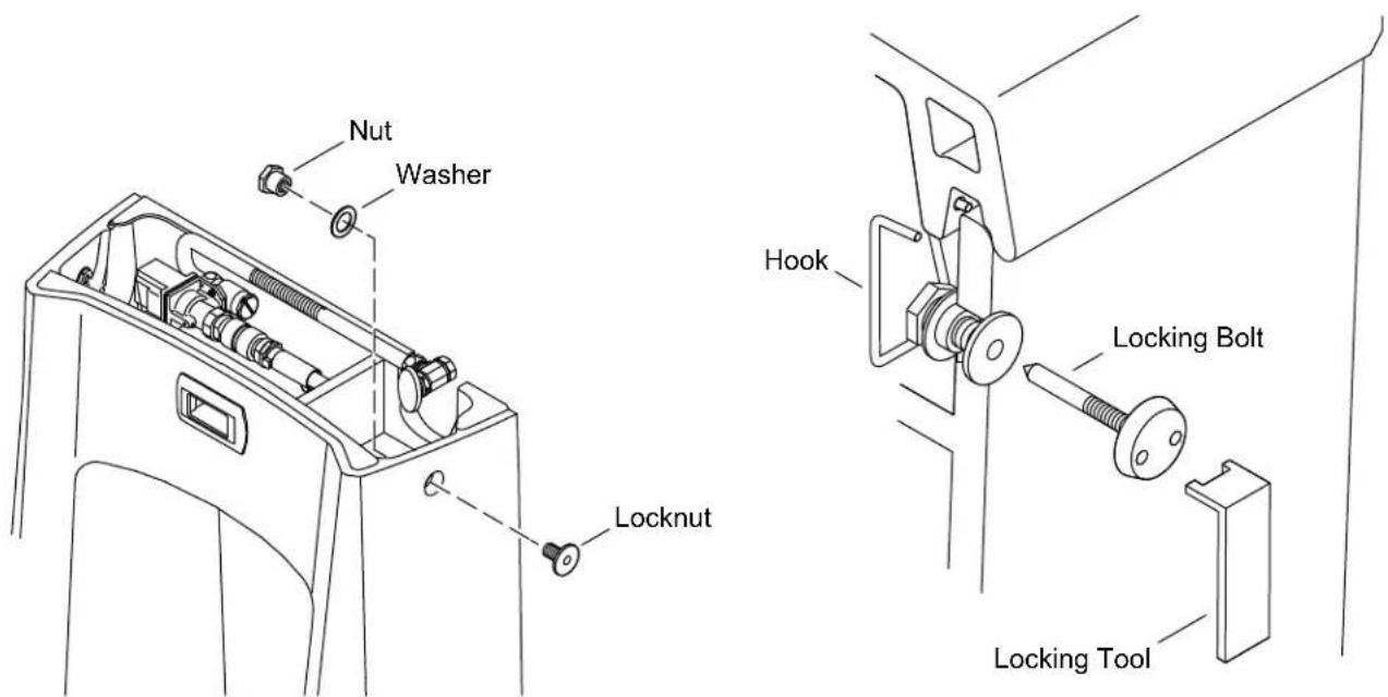
Nut Washer Locknut Hook Locking Bolt Locking Tool
CAUTION: Risk of product damage. Do not overtighten the locknut.
□ From the inside of the tank, insert a washer and nut into the hole located on the side of the tank.
□ From the outside of the tank, insert a locknut into the hole and through the nut.
□ Tighten the locknut. Do not overtighten the locknut.
☐ Repeat the previous steps for the other side.
□ Attach a hook to each side of the cover as shown.
□ Place the cover on the tank.
☐ Insert a locking bolt into each locknut and tighten with the provided locking tool.
□ Lift the cover to verify that the cover is properly locked.
□ Adjust the cover lock components, if necessary.
natural_image
Illustration of various mechanical and electrical tools including glasses, screwdriver, wrench, and switch (no text or labels)Clé de 5/8 po