Glassworks K-9719 - Shower system KOHLER - Free user manual and instructions
Find the device manual for free Glassworks K-9719 KOHLER in PDF.

User questions about Glassworks K-9719 KOHLER
0 question about this device. Answer the ones you know or ask your own.
Ask a new question about this device
Download the instructions for your Shower system in PDF format for free! Find your manual Glassworks K-9719 - KOHLER and take your electronic device back in hand. On this page are published all the documents necessary for the use of your device. Glassworks K-9719 by KOHLER.
USER MANUAL Glassworks K-9719 KOHLER
Please read these instructions carefully to familiarize yourself with the required tools, materials, and installation sequences. All information in these instructions is based on the latest product information available at the time publication. Kohler Co. reserves the right to make changes in product characteristics, packaging, or availability at any time without notice.
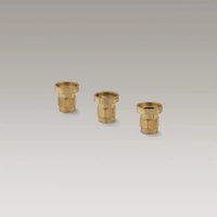
Before starting any installations, remove all supplied parts from wrappings, boxes or bags. Inspect all parts for damage. Use care when handling glass. Check all parts against exploded view, parts list and mounting hardware illustration. Notify place of purchase if parts are missing or broken. Read complete assembly instructions before beginning. Review illustrations with instructions.
TOOLS NEEDED
| •Measuring Tape | •Drill Bits |
| •Hacksaw (minimum 32 teeth/inch blade) | •Screwdrivers |
| •Miter Box | •Level |
| •Hammer | •Fine File |
| •Electric Drill | •Center Punch |
| •Caulking Gun | •Pencil |
| •Step Ladder | •Safety Glasses |
MATERIALS REQUIRED
- Glass Cleaner
2. FRAMEWORK REQUIREMENTS
CONSTRUCT FRAMING
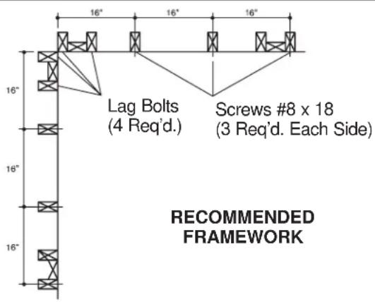
To assure screws are set in studs, locate framework as defined in recommended or alternate framework illustrations.
NOTE: Screw anchors are provided if #8 screws do not line up with studs.
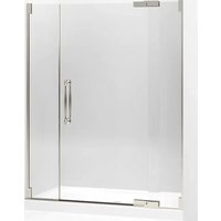
NOTE: Allow adequate clearance height for steam dome. Steam dome requires 9" (22.9cm) clearance above Glassworks shower doors. Total clearance height required is 91" (231.1cm) minimum: Whitecap receptor (if used) is 10" (25.4cm), Glassworks shower door is 72" (182.9cm), and steam dome is 9" (22.9cm).
NOTE: Sensor from steam unit will be mounted to bottom corner plate of steam dome. If routing of wire through finished wall is preferred, do so before installing finished wall.
Prior to proceeding with steam dome installation, install finished wall. Dome installation must be to finished wall.
Prior to proceeding with steam dome installation, install Whitecap unit (if used), Glassworks doors, and all associated accessories (steam generator, control, sensor, and steam outlet).
text_image
16" Lag Bolts (4 Req'd.) Screws #8 x 18 (3 Req'd. Each Side) 16" 18" 16" RECOMMENDED FRAMEWORK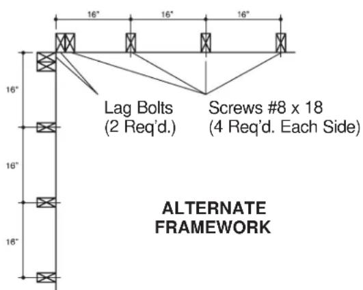
text_image
16" 16" 16" Lag Bolts (2 Req'd.) Screws #8 x 18 (4 Req'd. Each Side) 16" 16" 16" ALTERNATE FRAMEWORKMARK DRILLING LOCATIONS
Punch out hole centers in template and notch cutout, as indicated on template.
Place drill template on corner of shower enclosure against finished wall and level the template as illustrated. Template must be located flush to facing wall. Mark hole locations on finished wall. Put pencil mark in top corner.
Reverse template for opposite wall and align back corner of template with pencil mark and mark hole locations on that wall. Again flush rearward to corner.
Drill all holes 3/16" diameter.
For the four corner holes, counterbore only through the finish wall material to allow clearance for the 1/4" lag screws (5/16" diameter).
For all other hole locations, set shoulderless wall anchors into holes.
text_image
Put Pencil Mark Here Template Notch Cut-out Level Wall Corner Inside Shower Shower EnclosureINSTALL CORNER BRACKETS
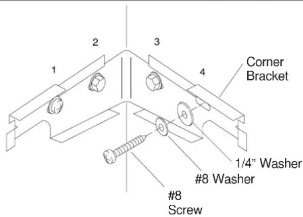
Loosely mount corner bracket in one of the two following methods, depending on whether the recommended or alternate framing method was used. Do not tighten bolts yet.
FOR RECOMMENDED FRAMING: Use lag screws through four stainless steel washers to mount corner bracket (four holes).
FOR ALTERNATE FRAMING: Use lag screws through stainless steel washers in hole locations #2 and #3 as illustrated. Use a #8 screw and a #8 flat washer and a #1/4" stainless steel flat washer in hole locations #1 and #4.
text_image
Corner Bracket 1/4" Washer #8 Washer #8 ScrewINSTALL HEADERS
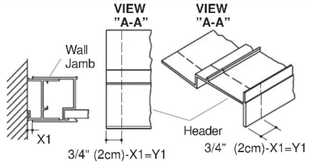
Header is supplied for an adjustment range per wall jamb of 3/4" (2cm). End of header usually needs trimming.
Measure the X-dimension (#1 or #2), which is the adjustment made to the shower door wall jamb for plumb at top of wall jamb.
Subtract the X-dimension from the 3/4" (2cm) maximum allowable adjustment to get the Y-dimension to be trimmed from the header.
Trim end very carefully and squarely. Use miter box, fine tooth hacksaw and file.
Repeat measurement process for opposite wall jamb and header.
Trim opposite end of header per new measurements.
Check header for fit on shower unit, and make adjustments as necessary.
text_image
Wall Jamb X1 VIEW "A-A" 3/4" (2cm)-X1=Y1 VIEW "A-A" Header 3/4" (2cm)-X1=Y1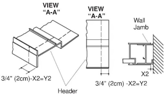
text_image
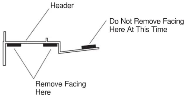
VIEW "A-A" 3/4" (2cm)-X2=Y2 Header VIEW "A-A" 3/4" (2cm) -X2=Y2 Wall Jamb X2From underside only of headers, remove facing from the two parallel strips of double-faced tape. Do not remove facing from the single strip of tape on the top of the header.
Press header around the perimeter of the system.
text_image
Header Do Not Remove Facing Here At This Time Remove Facing Here3. INSTALL SIDE RADIALS
Ensure wall anchors are installed in the holes for securing the side radials.
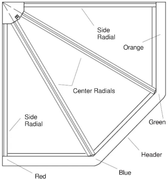
Determine right and left side radial assemblies: Match colored dot near one end of radial assembly with corresponding colored dot on header.
Apply silicone RTV to groove in back side of radial.
Back off nylon nut and and washer in the end of the side radials. This will allow decorative radial to slide back and forth on side radials.
text_image
Side Radial Orange Center Radials Green Red Blue Header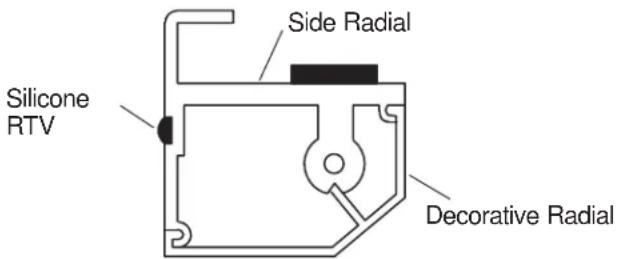
text_image
Side Radial Silicone RTV Decorative RadialRadial End View
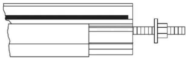
natural_image
Technical line drawing of a mechanical assembly with no visible text or symbolsRadial Side View
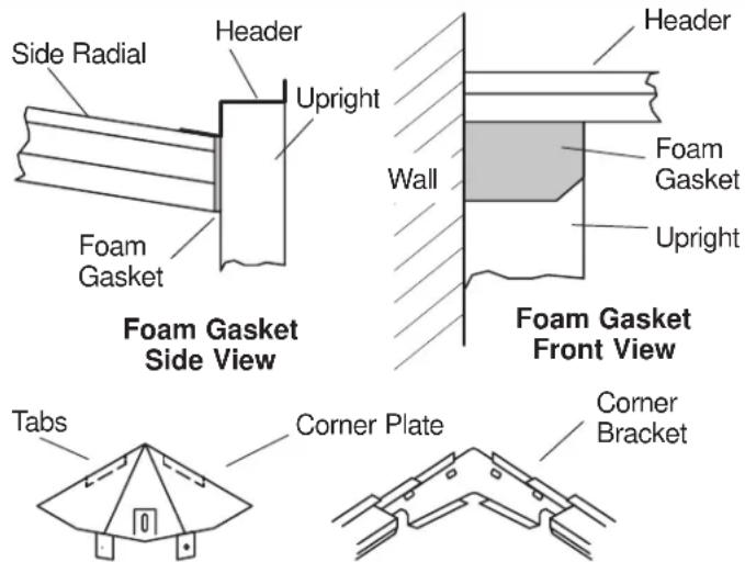
Apply foam gasket to shower door system by peeling off backing and locating foam directly in front of shower extrusion. Do not compress foam gasket yet.
Interlock shape of side radial into tabs in corner bracket.
Secure side radials walls with the screws provided.
Repeat on opposite side of unit.
After both side radials are installed and tightened, place corner plate tabs into receptors on corner bracket and tighten corner bracket mounting hardware (lag bolts or bolts and screws).
Move nylon nuts forward to slightly compress foam gaskets. Adjust gaskets if necessary.
text_image
Side Radial Header Upright Foam Gasket Foam Gasket Side View Header Wall Foam Gasket Upright Foam Gasket Front View Tabs Corner Plate Corner Bracket4. INSTALL CENTER RADIALS
Match center radials to positions on headers by colored markings on hanger end of radials and mounting position on headers.
Remove first nut and washer from each center radial assembly. Back off the remaining nut to allow decorative cover to slide rearward.
Put stud through hole in corner bracket and drop front of center radials down so hanger hooks on the shower door upright extrusion.
NOTE: If wall jambs are installed at minimum condition, it may be necessary to eliminate front hex nut on center radial.
Apply foam gaskets to both mating faces of center radials. Apply gasket to end of radial.
Replace washer and nylon nut. Alternately tighten rear nuts on left and right radials to snug. Do not overtighten.
Tighten forward nuts to slightly compress foam gaskets.
Readjust side radials if glass mounting surfaces are not aligned in the same plane on top of header and side radial extrusions.
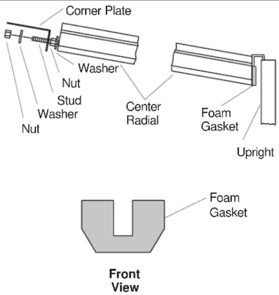
text_image
Corner Plate Washer Nut Stud Washer Nut Center Radial Foam Gasket Upright Front View5. INSTALL SIDE GLASS PANELS
Install side glass panels and bottom cover plate before installing center panel - do not install center panel yet.
For one side panel at a time, remove protective facing from the double-sided tape on the headers and radials. There is no tape in the corner bracket area.
NOTE: Be sure of alignment to all mounting surfaces prior to placing glass.
Place front edge of glass forward in header and visually line up sides as glass is lowered into place.
Repeat for other side panel.
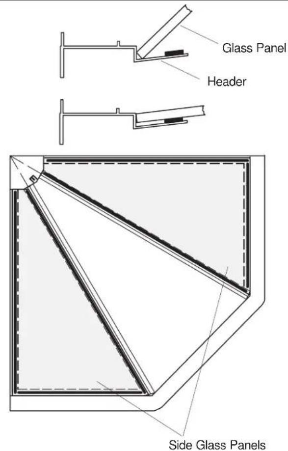
text_image
Glass Panel Header Side Glass Panels6. INSTALL BOTTOM COVER PLATE
Trim back corner of bottom cover plate, as necessary, with a file to match radius of shower enclosure wall.
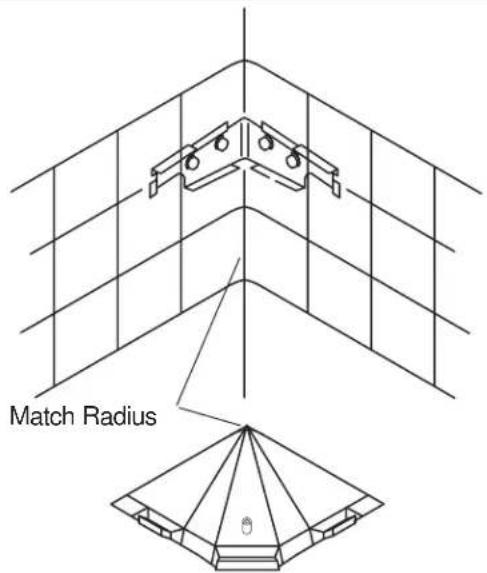
text_image
Match RadiusStart the #12 x 1-1/4" self-tapping screw, through the corner mounting plate and into the bottom cover plate.
Check alignment so cover will seal against side glass panels.
Apply small bead (about 1/8" Dia.(3mm)) of RTV sealant 1/4" (6mm) behind and parallel to front edge of bottom cover plate.
Insert two pins at rear of bottom cover plate into receiving slots of corner bracket.
Support cover with hand while tightening screw mount. Do not overtighten screw.
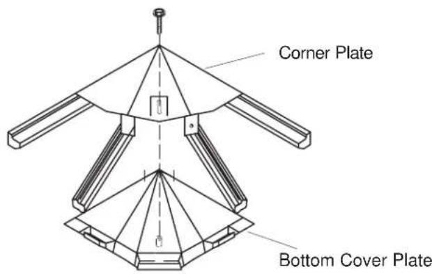
text_image
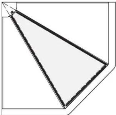
Corner Plate Bottom Cover Plate7. INSTALL CENTER GLASS
Remove protective backing from tape for center glass panel.
Align and lower glass into mounting area as per side glass panel instructions.
Glass should extend over bottom cover plate.
natural_image
Geometric diagram of a triangular prism with dashed lines indicating hidden edges (no text or symbols)8. INSTALL CENTER GLASS
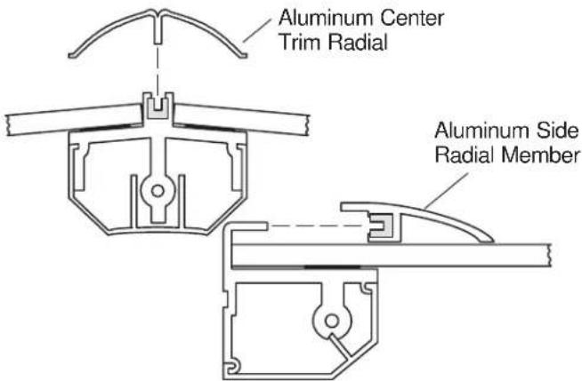
Insert trim into vinyl mount strip (center).
Apply trim strip with vinyl mounting strip to corresponding protrusion as shown. Push trim pieces into vinyl mounting strips.
text_image
Aluminum Center Trim Radial Aluminum Side Radial Member9. INSTALL CENTER GLASS
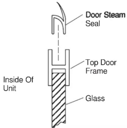
Install door steam seal in top door extrusion of K-9717 neo-angle door system.
text_image
Door Steam Seal Top Door Frame Glass Inside Of Unit10. INSTALL CENTER GLASS
Remove protective backing from tape on underside of three surfaces of cover plate and place on top of installation. Tape will adhere to glass surface.

WARNING: Risk of Personal Injury or Property Damage: DO NOT LEAN ON GLASS.
Cover Plate

natural_image
Pure architectural line drawing of a window frame structure without any text, numbers, or symbolsCONSUMER RESPONSIBILITIES
Your Kohler Shower Door will remain beautiful if you take care of it. It is recommended that you replace seals, when they show signs of wear, yellowing, or are not watertight. Refer to the exploded parts page for Kohler Service Parts.
Water conditions in various parts of the country will determine any extra cleaning attention you may have to give your new shower door. A simple routine of daily care will keep your shower enclosure looking like new.
Kohler Co. does not recommend the use of harsh abrasive cleansers on any of its products. Harsh cleansers will damage the metal or glass finish on your shower door.
CALLUSFORHELP
Questions? Problems? First review the installation instructions to ensure correct installation. For additional assistance, call our Customer Service Department for direct help. You may also contact us at our web site listed below.
In the U.S.A., call 1-800-4-KOHLER
In Mexico, call 001-877-680-1310
In Canada, call 1-800-964-5590
THE BOLD LOOK
OF KOHLER®
www.kohler.com
G UÍA D E
INSTALACIÓN
GLASSWORKS™ CÚPULADEVAPOR
K-9719
THE BOLD LOOK OF KOHLER®