
MJ180 - Workbench SCHEPPACH - Free user manual and instructions
Find the device manual for free MJ180 SCHEPPACH in PDF.

| Product type | Workbench / Multi-function bench vise |
| Brand | Scheppach |
| Model | MJ180 |
| Max jaw opening | 0 - 956 mm |
| Max clamping force | 1000 kg |
| Max pedal load | 100 kg |
| Jaw material | Urethane (jaw pads) |
| Weight | 16 kg |
| Dimensions (folded) | 275 x 775 x 295 mm |
| Dimensions (unfolded) | 980 x 1000 x 860 mm |
| Main functions | Clamping, unclamping, one-sided clamping, clamping large workpieces (up to 956 mm), use as anvil, use as vise |
| Clamping mechanism | Clamping pedal with lock/unlock |
| Reversible sliding jaw | Yes, for pieces from 460 to 956 mm |
| Safety instructions | Do not use as a step stool; check the leg lock; keep hands away from moving parts; support large workpieces |
| Routine maintenance | Removal of urethane jaw pads (screwdriver lever); occasional lubrication of ratchet spindle |
| Optional accessories | Special jaws for logs and posts (galvanized steel, Ø up to 175 mm) |
| Warranty | Legal warranty, wear parts excluded (blade), repairs by authorized professionals |
| Recommended uses | Sawing, chainsaw chain sharpening, clamping square tubes, metalworking (anvil) |
| Transport | Integrated carrying handle (rear foot folded) |
Frequently Asked Questions - MJ180 SCHEPPACH
User questions about MJ180 SCHEPPACH
0 question about this device. Answer the ones you know or ask your own.
Ask a new question about this device
Download the instructions for your Workbench in PDF format for free! Find your manual MJ180 - SCHEPPACH and take your electronic device back in hand. On this page are published all the documents necessary for the use of your device. MJ180 by SCHEPPACH.
USER MANUAL MJ180 SCHEPPACH
natural_image
Mechanical bipod device with labeled components (no readable text or symbols beyond branding)natural_image
Person assembling a blue mechanical device with black components (no visible text or symbols)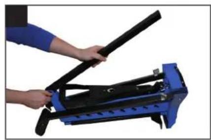
natural_image
Person using a blue mechanical device to lift a black lever (no text or symbols visible)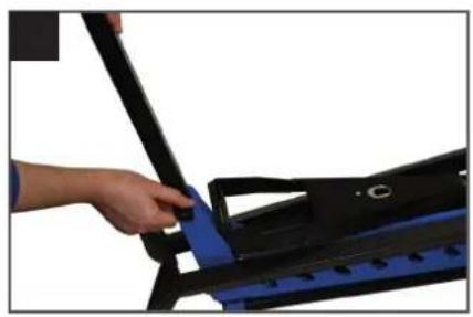
natural_image
Close-up of a hand using a black tool to adjust or install a blue mechanical component (no text or symbols visible)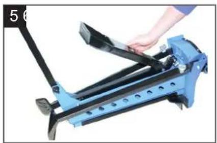
natural_image
Close-up of a blue bicycle leg mechanism being adjusted by a hand (no text or symbols visible)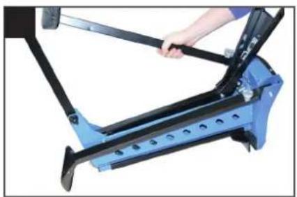
natural_image
Close-up of a blue and black bicycle frame with a hand adjusting the shaft (no text or symbols visible)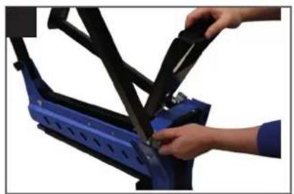
natural_image
Close-up of hands installing or adjusting a blue bicycle seat frame (no text or symbols visible)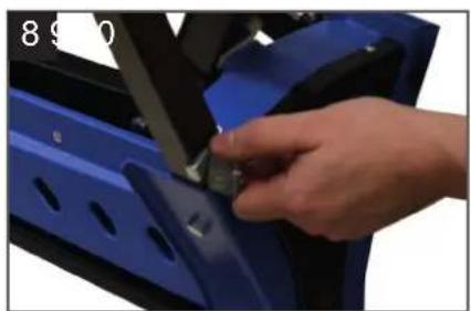
natural_image
Close-up of a hand adjusting a blue car door panel with a tool (no visible text or symbols)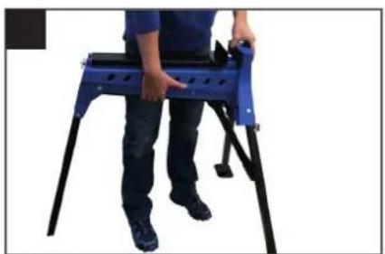
natural_image
Person standing on a blue and black metal platform, no visible text or symbols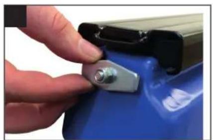
natural_image
Close-up of a hand pressing a metallic clip onto a blue battery (no text or symbols visible)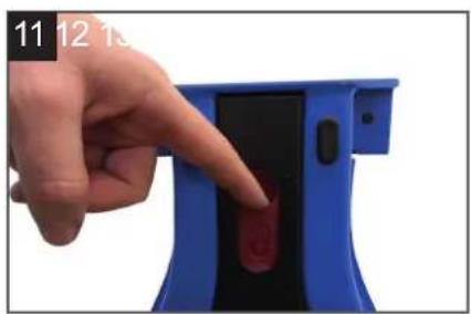
natural_image
Hand pointing at a blue electronic device with a red button (no text or symbols visible)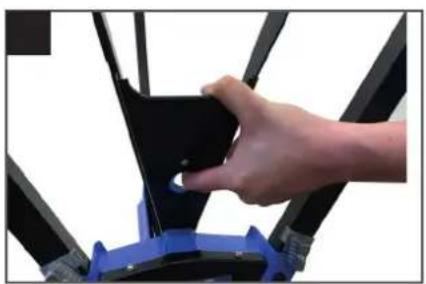
natural_image
Close-up of a hand adjusting a black mechanical component with blue base (no visible text or symbols)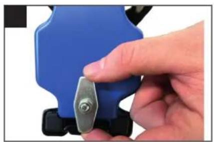
natural_image
Close-up of a hand holding a blue plastic tool with a metallic screw (no text or symbols visible)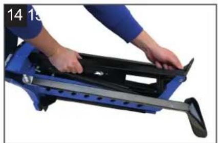
natural_image
Person using a blue and black mechanical device with a roller, no visible text or symbols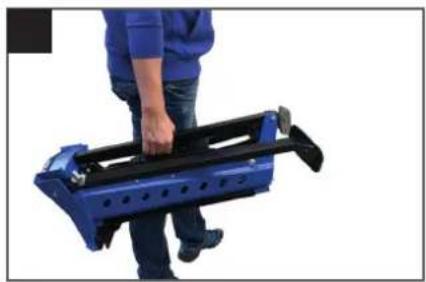
natural_image
Person holding a blue and black mechanical device (no visible text or symbols)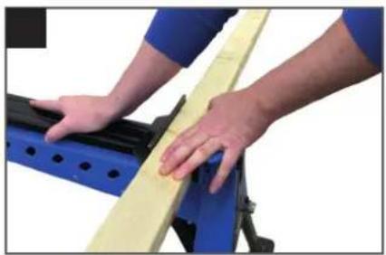
natural_image
Close-up of hands operating a yellow balance scale on a blue and black mechanical frame (no text or symbols visible)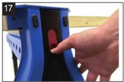
natural_image
Hand inserting a red circular button into a blue mechanical device (no text or symbols visible)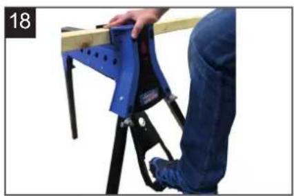
natural_image
Person using a blue safety bracket to lift a wooden beam, no visible text or symbols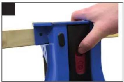
natural_image
Close-up of a hand holding a blue mechanical device with black buttons and red button, against a beige background (no text or symbols visible)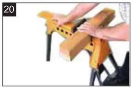
natural_image
Close-up of hands assembling a wooden block clamped in black metal (no text or symbols visible)
natural_image
Close-up of a mechanical clamp or bracket with blue base and black top, no visible text or symbols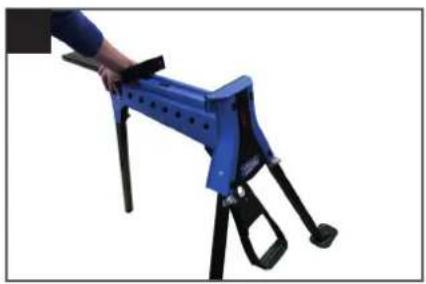
natural_image
Blue and black mechanical device with tripod base (no visible text or symbols)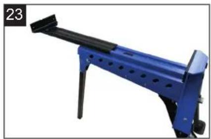
natural_image
Blue mechanical lever device with black handle and mounting feet (no visible text or symbols)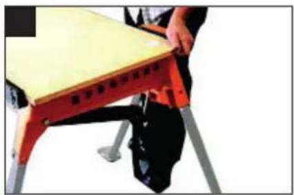
natural_image
Person sitting on a red and black robotic platform with a wooden table (no visible text or symbols)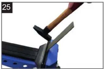
natural_image
Close-up of a hand using a hammer to cut a blue metal object, no visible text or symbols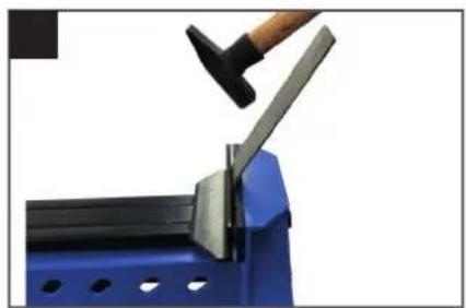
natural_image
Close-up of a hand using a hammer to lift a metal bracket on a blue metal frame (no text or symbols visible)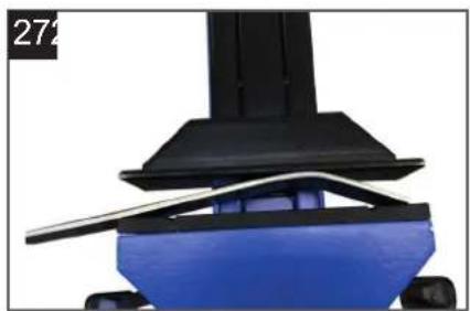
natural_image
Close-up of a mechanical component with blue base and black top, no visible text or symbols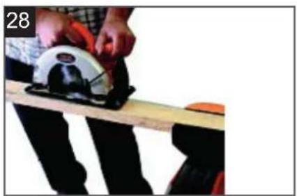
natural_image
Person using a power saw on a wooden workbench, no visible text or symbols
natural_image
Close-up of a wooden board with a white and red metal object, possibly a tool or machine component (no visible text or symbols)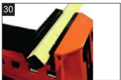
natural_image
Close-up of a red and black mechanical component with yellow adhesive tape (no visible text or symbols)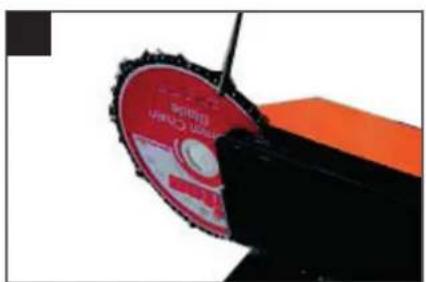
natural_image
Close-up of a red and black mechanical disc with serrated edges, partially cut off (no visible text or symbols)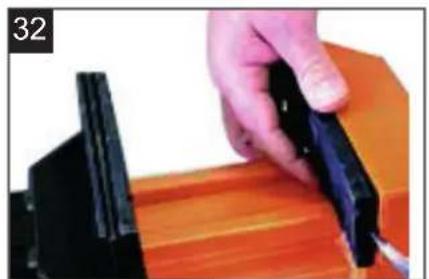
natural_image
Close-up of a hand using a black tool to cut or adjust a wooden block (no text or symbols visible)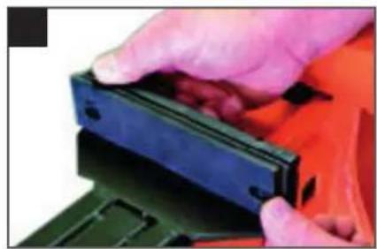
natural_image
Close-up of hands holding a black plastic clip against an orange background (no text or symbols visible)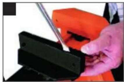
natural_image
Close-up of a hand using a tool to adjust or install a black mechanical component (no visible text or symbols)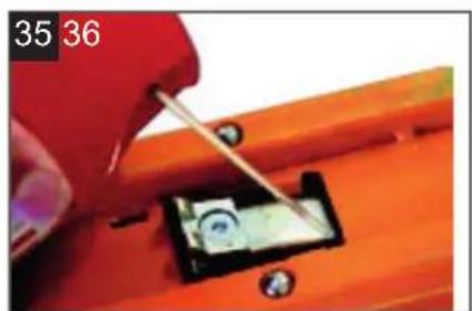
natural_image
Close-up of a hand using a tool to adjust a small electronic component on an orange workbench (no visible text or symbols)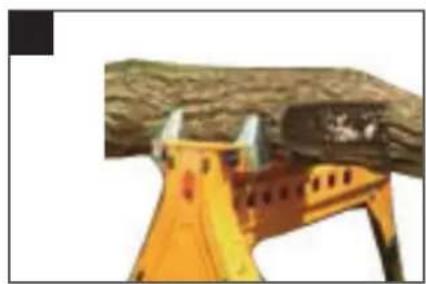
natural_image
Close-up of a yellow construction helmet against a tree trunk (no text or symbols visible)Inhaltsverzeichnis:
Günzburger Straße 69
D-89335 Ichenhausen
VEREHRTER KUNDE,
5. AUFBAU (Fig 2-10)
- Introduction 12
- Layout 12
- Safety instructions 12
- Specifications 13
- Setting up 13
- Operation 13 - 14
- Service & Maintenance 14
- Optional accessories 14
Explanation of the symbols on the equipment


Instruction note


Instruction warning

Do not use this product as a step or platform
1. Introduction
MANUFACTURER:
scheppach
Günzburger Straße 69
D-89335 Ichenhausen
DEAR CUSTOMER,
We hope your new tool brings you much enjoyment and success.
NOTE:
According to the applicable product liability laws, the manufacturer of the device does not assume liability for damages to the product or damages caused by the product that occurs due to:
- Improper handling,
• Non-compliance of the operating instructions, - Repairs by third parties, not by authorized service technicians,
- Installation and replacement of non-original spare parts,
• Application other than specified, - A breakdown of the electrical system that occurs due to the non-compliance of the electric regulations and VDE regulations 0100, DIN 57113 / VDE0113.
WE RECOMMEND:
Read through the complete text in the operating instructions before installing and commissioning the device. The operating instructions are intended to help the user to become familiar with the machine and take advantage of its application possibilities in accordance with the recommendations. The operating instructions contain important information on how to operate the machine safely, professionally and economically, how to avoid danger, costly repairs, reduce downtimes and how to increase reliability and service life of the machine.
In addition to the safety regulations in the operating instructions, you have to meet the applicable regulations that apply for the operation of the machine in your country. Keep the operating instructions package with the machine at all times and store it in a plastic cover to protect it from dirt and moisture. Read the instruction manual each time before operating the machine and carefully follow its information. The machine can only be operated by persons who were instructed concerning the operation of the machine and who are informed about the associated dangers. The minimum age requirement must be complied with.
2. Layout (Fig. 1)
FEATURES
- Fixed jaw facing
- Moving jaw facings (2 pieces)
- Moving jaw locking tab
- Body
- Rear leg locking knob
- Rear leg
- Foot plates
- Foot pedal
- Front legs
- Foot pedal locking latch
- Front leg locking knobs
- Extension Tray mounting holes
- Lock / release switch
- Fixed jaw
- Moving jaw
3. SAFETY INSTRUCTIONS
GENERAL SAFETY WARNINGS
Read and understand all instructions. Failure to follow all instructions listed below, may result in personal injury.
- Make sure all moving parts are free from interference.
- Keep hands clear of all moving parts.
- Ensure multi purpose working station is set up on firm ground in a stable manner.
- Be aware of overbalancing. When a large piece is cut from one end of a job, the remaining piece may be heavy enough to overbalance the multi purpose working station. Always ensure the workpiece is well supported.
- Check to make sure that all fixing screws and knobs are tight and all legs are locked into place before operating the multi purpose working station.
- The tool must be used only for its prescribed purpose. Any use other than those mentioned in these instructions will be considered a case of misuse.
- The manufacturer shall not be liable for any damage or injury resulting from such cases of misuse.
- The manufacturer shall not be liable for any changes made to the tool nor for any damage resulting from such changes.
4. SPECIFICATIONS
| MJ 180 | |
| Delivery Status | |
| Multi purpose working station | |
| Log & Pole Jaws (Optional Accessories) | |
| Technical Data | |
| Clamping range | 0 - 956 mm / 37 5/8" |
| Clamping force | 1000 kg / 2200 lbs |
| Maximum load kg | 100 kg / 220 lbs |
| Jaws | Urethan |
| Weight kg | 16 kg / 35.2 lbs |
| Folded size | 275 x 775 x 295 mm10 7/8"x 30 1/2"x 11 39/64" |
| Standing size | 980 x 1000 x 860 mm38 37/64"x 39 25/64"x 33 27/32" |
5. SETTING UP (Fig. 2-10)
- With multi purpose working station placed upside down on the ground, loosen the rear leg locking knob (5) and slide the rear leg from its storage position. Pivot the leg just clear of the front face. Slide it all the way forward then lift and slide it fully into its housing at the rear. Tighten the knob. Fig. 2-4
- Raise the foot pedal (8) until it "clicks" into position. Fig. 5
- Pivot the front legs (9) out as far as they will go then turn the front leg locking knobs (11) clockwise until the rounded section of the knob tightens onto the leg housing, as shown. Several turns may be necessary on initial set-up until the clamps tighten into place – a half turn is all that is required to release the legs when folding. Fig. 6-8
- Turn the multi purpose working station upright and recheck that all legs are locked firmly in position. Fig. 9
- Rotate the moving jaw locking tab (3) to the horizontal position and multi purpose working station is now ready for use. Fig. 10
FOLDING (Fig. 11-15)
Folding is the reverse procedure of above. Ensure that:
- The lock / release switch is in the "unlock position". Fig. 11
- The foot pedal locking latch (10) is used to release and fold the foot pedal. Fig. 12
- The moving jaw locking tab (3) is in the "vertical" position to prevent the jaw from sliding out. Fig. 13
- The rear leg is engaged fully into its housing and the rear leg locking knob (5) is tightened firmly. Fig. 14
When in its folded position the rear leg becomes a carrying handle, to aid in transportation. Fig. 15
6. OPERATION
CLAMPING (Fig. 10, 16-18)
- Check that the moving jaw locking tab (3) is set to the horizontal position and push the moving jaw (15) back until your workpiece fits between the jaws. Fig. 10
- Place the workpiece against the fixed jaw(14) and slide the moving jaw forward until it touches the workpiece. Fig.16 The jaw can also be advanced forward by pressing the foot pedal repeatedly.
- Slide the lock / release switch (13) down to the "lock" position. Fig. 17 If preferred the switch can be locked after the work is clamped.
- Apply downward pressure on the foot pedal (8) until sufficient clamping force has been applied. Fig. 18
For extra force you may stand on the foot pedal (maximum 100kg) but do not jump on it, as you could damage the unit.
RELEASING (Fig. 18-20)
- Slide the lock/release switch (13) up to the "release" position. Fig. 19
- Push on the foot pedal then allow it to return up and release the workpiece. Ensure you are supporting the workpiece to prevent it from falling once the jaw is released. If you have clamped the object very tightly, you may need to exert more pressure on the foot pedal before it will release. Fig. 18
- Slide the moving jaw back and remove your workpiece. Fig. 20
CLAMPING ON ONE SIDE OF THE JAW (Fig. 21)
On occasions, large or awkward workpieces can only be clamped on one side of the jaws. Always fit a spacer (the same thickness as your workpiece) to the other side of the jaws, to prevent the moving jaw from skewing.
CLAMPING LARGE OBJECTS
(460mm to 956mm) (Fig. 10,11, 22-24)
The moving jaw can be reversed to accommodate workpieces greater than 460mm and less than 956mm.
- Set the lock / release switch (13) to the "release" position and ensure that the foot pedal is released. Fig. 11
- Check that the moving jaw locking tab (3) is in the horizontal position. Fig. 10
- Slide the moving jaw (15) fully from its tracks. Fig.22
-
Rotate it 180 degrees and re-insert it into the tracks. Fig. 23
-
Whenever clamping objects with the moving jaw reversed, ensure the workpiece sits down onto the sliding jaw, and is parallel to it. Avoid clamping workpieces at the top of the jaws (with a gap between the workpiece and the base of the moving jaw) as excessive pedal pressure could damage the unit.
- When clamping large or heavy materials, provide outboard support (such as a trestle) to prevent multi purpose working station from tipping over.
Clamping workpieces up to 956mm can be achieved by removing the jaw facings (see removing the urethane jaw facings). Fig. 24
USING AS AN ANVIL (Fig. 25, 26)
The fixed jaw is sufficiently robust to be used as an anvil for strip metal work. Do not use the moving jaw as an anvil. You could damage it.
USING AS A PRESS (Fig. 27)
When the lock / release switch (13) is in the release position multi purpose working station can be used as a press.
With each full stroke of the foot pedal, the moving jaw will advance about 25mm.
GENERAL OPERATING ADVICE
When working along the line of the jaws, place your foot on the foot plates (7) to prevent multi purpose working station from moving.
Ripping A Plank (Fig. 28-29)
- When ripping a plank, stop your cut before reaching the jaws.
- Remove the workpiece and re-clamp with sufficient amount of the cut beyond the jaws, so that you can drop in your saw to recommence your cut.
- Before clamping, insert a spacer slightly thicker than your saw cut, at the jaw area, to keep the cut open.
Clamping Square Tubing (Fig. 30)
It is easier to hacksaw square tubing or similar on the diagonal.
Use the V-grooves in the urethane jaws to securely hold your material.
Sharpening Chainsaws (Fig. 31)
multi purpose working station makes an ideal clamp to hold a chainsaw or chainblade while sharpening the teeth.
If sharpening a chainsaw use two wooden blocks, either side of the bar, to ensure the clamping jaws are clear of the chain, which can then be rotated as each tooth is filed.
7. SERVICE & MAINTENANCE
- Any damage to multi purpose working station should be repaired and carefully inspected before use, by qualified repair personnel.
- Servicing should only be carried out using original scheppach replacement parts.
- The manufacturer will not be responsible for any damage or injury caused by unauthorized repair or mishandling of the machine.
REMOVING THE URETHANE JAW FACINGS (Fig. 32-35)
The jaw facings can be removed to achieve a greater clamping range, or for replacement if worn or damaged.
- The fixed jaw facing (1) is removed by prying it off the fixed jaw (14) using a screwdriver or similar. Fig. 32
- To remove the moving jaw facing, push the backing face to the right (when viewed from the front of multi purpose working station) to disengage the connection pins. The backing face can then be removed, allowing the front to be pulled off the moving jaw.g. 33,34
The pawl carrier pivot pin may occasionally require a small amount of spray lubricant, as shown Fig. 35, if it doesn't pivot smoothly.
8. OPTIONAL ACCESSORIES
LOG AND POLE GRIPPING JAWS (Fig. 36)
Suitable for gripping logs or poles, these jaws also bolt onto the standard steel jaws and are formed from steel plate, zinc plated for corrosion resistance. Logs or poles up to 175mm in diameter are gripped firmly for chain sawing, drilling, rebating etc.
Table des matières:
Günzburger Straße 69
D-89335 Ichenhausen
CHER CLIENT,
Günzburger Straße 69
D-89335 Ichenhausen
VÁŽENÝ ZÁKAZNÍKU,
POUŽITÍ JAKO KOVADLINY (obr. 25, 26)
Günzburger Straße 69
D-89335 Ichenhausen
VÁŽENÝ ZÁKAZNÍK,
UPNUTIE (obr. 10, 16 – 18)
Garantie DE
Apparent defects must be notified within 8 days from the receipt of the goods. Otherwise, the buyer's rights of claim due to such defects are invalidated. We guarantee for our machines in case of proper treatment for the time of the statutory warranty period from delivery in such a way that we replace any machine part free of charge which provably becomes unusable due to faulty material or defects of fabrication within such period of time. With respect to parts not manufac
tured by us we only warrant insofar as we are entitled to warranty claims against the upstream suppliers. The costs for the installation of the new parts shall be borne by the buyer. The cancel - lation of sale or the reduction of purchase price as well as any other claims for damages shall be excluded. The saw blade is a consumable item and explicitly excluded from any warranty.