
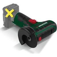
PWSAP 20-Li F6 - Cordless angle grinder PARKSIDE - Free user manual and instructions
Find the device manual for free PWSAP 20-Li F6 PARKSIDE in PDF.


| Brand | Parkside |
| Model | PWSAP 20-Li F6 |
| Category | Cordless angle grinder |
| Rated voltage | 20 V = |
| No-load speed | 10000 min⁻¹ |
| Weight with battery (4 Ah) | ≈ 2.35 kg |
| Max. disc diameter | 125 mm |
| Disc bore | 22.23 mm |
| Max. thickness of cutting disc | 1.2 mm |
| Max. thickness of grinding disc | 6 mm |
| Spindle thread | M14, length ≤ 11 mm |
| Compatible battery | X 20 V TEAM (Li-Ion, 20 V) |
| Compatible charger | X 20 V TEAM range |
| Sound power level (LWA) | 95.7 dB (K=3 dB) |
| Sound pressure level (LpA) | 87.7 dB (K=3 dB) |
| Vibrations (handle) | ≤ 2.5 m/s² (K=1.5 m/s²) |
| Adjustable speed | Yes, 6 levels |
| Functions | Grinding, cutting, brushing |
| Adjustable protective guard | Yes, tool-free |
| Auxiliary handle | Yes, 3 positions |
| Spindle lock | Yes |
| Connectivity | Bluetooth via Smart battery (PAPS 204/208) |
| Warranty | 5 years |
| Protection class | IPX0 |
Frequently Asked Questions - PWSAP 20-Li F6 PARKSIDE
User questions about PWSAP 20-Li F6 PARKSIDE
0 question about this device. Answer the ones you know or ask your own.
Ask a new question about this device
Download the instructions for your Cordless angle grinder in PDF format for free! Find your manual PWSAP 20-Li F6 - PARKSIDE and take your electronic device back in hand. On this page are published all the documents necessary for the use of your device. PWSAP 20-Li F6 by PARKSIDE.
USER MANUAL PWSAP 20-Li F6 PARKSIDE
PDF ONLINE
parkside-diy.com

natural_image
Black and white photo of a parkside electric saw with a mounted device (no visible text or symbols)
Akku-Winkelschleifer / Cordless Angle Grinder / Meuleuse d'angle sans fil PWSAP 20-Li F6
DE AT CH
Cordless Angle Grinder
Translation of the original instructions
NL BE
Accu-haakse slijpmachine
Before reading, unfold the page containing the illustrations and familiarise yourself with all functions of the device.
FR BE
natural_image
Two mechanical components: a black cylindrical device with threaded end and a transparent plastic tool with a pointed tip, both shown without any visible text or symbols.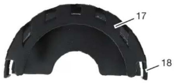
Inhaltsverzeichnis
Einleitung......4
Introduction......32
Proper use....33
Scope of delivery/accessories....33
Overview.... 33
Description of functions...... 34
Technical data.... 34
Safety information.... 35
Meaning of the safety information.... 36
Pictograms and symbols......36
General Power Tool Safety Warnings.... 37
Safety information for angle grinders.... 39
Residual risks.... 43
Preparation......44
Control elements......44
Fitting the auxiliary handle...... 44
Attaching and removing the guard cover.... 44
Attaching and removing the attachment tool.... 44
Fitting and removing the attachment on the guard cover.... 46
Checking the battery charge level.... 46
Charging the battery...... 47
Operation......47
Working instructions...... 47
Inserting and removing the battery.... 48
Adjusting the guard cover......49
Adjusting the speed.... 49
Switching on and off.... 49
Parkside app.... 50
Cleaning, maintenance and storage....50
Cleaning.... 50
Maintenance....51
Storage....51
Troubleshooting....51
Transport.... 52
Disposal/environmental protection....52
Disposal instructions for rechargeable batteries....52
Service....53
Guarantee....53
Repair service....54
Service Centre....54
Importer....54
Spare parts and accessories......55
Translation of the original EC declaration of conformity....56
Exploded view....303
Introduction
Congratulations on purchasing your new cordless angle grinder (hereafter referred to as device or power tool). You have chosen a high-quality device. This device was quality-tested and subjected to a final inspection during production, therefore ensuring proper functioning of your device.

The instruction manual forms part of this device. It contains important information on safety, use and disposal. Read the instruction manual carefully. Familiarise yourself with the controls and how to use the device correctly. Use the device only as described and for the stated fields of application. Store the instruction manual carefully and ensure that all documents are handed over in the event that the device is passed on to another user.
Proper use
This power tool is intended to function as a grinder, wire brush or cut-off tool.
Operations such as sanding, polishing or hole cutting are not to be performed with this power tool. Do not use liquid coolants such as water. Do not work with materials that contain hazardous substances, e.g. asbestos or lead.
Only operate in dry areas.
The device is intended for use by adults. Children under the age of 16 may not use the device, except under supervision.
Any other use that is not expressly permitted in this instruction manual may pose a serious hazard to the user and result in damage to the device. The operator or user of the machine is responsible for any accidents or personal injury and/or material damage to third parties or their property. The machine is intended to be used by do-it-yourselfers. It was not designed for heavy commercial use. The warranty is void in the case of commercial use. The manufacturer is not liable for damage caused by improper use or incorrect operation.
The device is part of the
X 20 V TEAM series and can be operated with batteries of the X 20 V TEAM series. Batteries of the X 20 V TEAM series may only be charged using chargers of the X 20 V TEAM series.
Scope of delivery/ accessories
Unpack the device and check that everything is present.
Dispose of the packaging material properly.
- Cordless Angle Grinder
• Auxiliary handle (pre-assembled)
• Cutting disc (pre-assembled)
- Guard cover, Attachment
- Chuck key
- Storage case
• Translation of the original instructions
The rechargeable battery and charger are not included in delivery.
Overview
The illustrations for the device can be found on the front and back fold-out page.
1 Handle
2 Battery holder
3 Dust protection grille
4 Auxiliary handle
5 Guard cover
6 Cutting disc
7 Direction of rotation arrow
8 Spindle lock
9 Holder (Auxiliary handle)
10 "Connected" display
11 Charge level indicator (Device)
12 Display, Speed level
13 Unlock button
14 Speed button
15 On/Off button
16 Chuck key
17 Attachment (Guard cover)
18 Lock (Attachment)
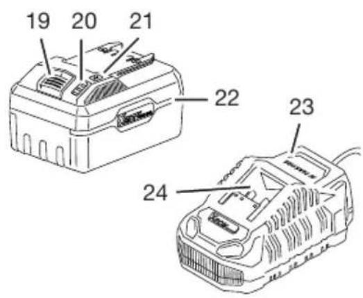
19 Battery release
20 Charge level indicator
21 Button (Charge level indicator)
22 Battery
23 Charger
24 Charging slot
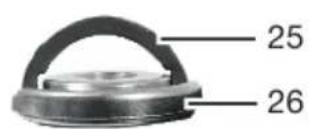
25 Bracket (Keyless chuck)
26 Keyless chuck
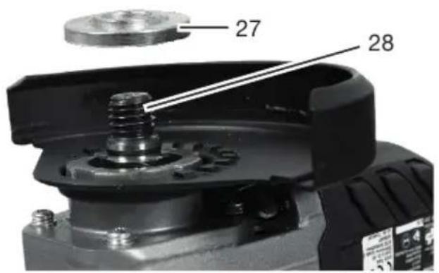
27 Mounting flange
28 Uptake spindle
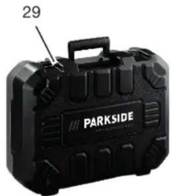
29 Storage case
Fig. A
30 Notch
31 Release lever (Guard cover)
Description of functions
The very fast rotating attachment tool enables clean grinding, cutting or brushing of metal.
Special attachment tools are provided for each individual application. Please refer to the information from the manufacturer.
Please refer to the descriptions below for information on how the operating elements work.
Technical data
Cordless Angle Grinder
PWSAP 20-Li F6
Rated voltage U 20 V =
Protection type ......IPX0
No-load rotation speed n_0
10000 min ^-1
Weight with battery (20 V, 4 Ah)
.....≈2.35 kg
Mounting flange .....Ø22.23 mm
Thread M14
Thread length of grinding spindle
≤11 mm
Sound power level ( L_WA )
95.7 dB; K_WA = 3 dB
Sound pressure level ( L_pA )
87.7 dB; K_pA=3 dB
Vibration ( a_h )
- Handle ....≤2.5 m/s ^2 ; K=1.5 m/s ^2
– Auxiliary handle
≤2.5 m/s^2; K=1.5 m/s^2
Battery .....Li-Ion
Temperature .... ≤50 °C
- Charging 4 - 40 °C
- Operation ...... -20 - 50 °C
- Storage 0 - 45 °C
PARKSIDE Performance Smart
battery Smart PAPS 204 A1/
Smart PAPS 208 A1
- Frequency f .....2400 - 2483.5 MHz
- transmitted power ....≤20 dBm
Cutting disc ......A24 Q BF
(included)
Manufactured in compliance with EN 12413:2019
Disc rotational speed n_max
12200 min ^-1
Disc speed v_0 ...... ≤80 m/s ^2*
Outside diameter .....Ø125 mm
Borehole ...... ∅22.23 mm
Thickness .... ≤1.2 mm
* The grinding disc must withstand a rotational speed of 80 m/s.
Levels of noise and vibration were determined according to the standards and regulations in the declaration of conformity.
The specified total vibration value and the stated noise emission value have been measured according to a standardised test method and can be used to compare one power tool with another. The specified total vibration value and the stated specified noise emission value can also be used for a provisional assessment of the load.
⚠ WARNING! The vibration and noise emissions may deviate from the specified values during actual use of the power tool, depending on how the power tool is being used. Try to keep the exposure to vibrations as low as possible. An example of a measure to reduce vibration exposure is limiting the working hours. All
parts of the operating cycle have to be considered while doing so (for example, times when the power tool is switched off and times when it is switched on but running without any load).
⚠ WARNING! Grinding thin metal sheet or other well vibrating structures with a large surface area can result in increased noise exposure and a much (up to 15 dB) higher overall noise emission than the specified noise emission values. Use heavy flexible damping mats or similar to prevent sound radiation from such workpieces. Take into account the increased noise emission and wear appropriate hearing protection.
Charging time
We recommend that you operate this appliance with the following batteries only: PAP 20 B1, PAP 20 B3, Smart PAPS 204 A1, Smart PAPS 208 A1
We recommend charging these batteries with the following chargers: PLG 20 A3, PLG 20 A4, PLG 20 C1, PLG 20 C2, PLG 20 C3, PLG 201 A1, PDSLG 20 A1, PDSLG 20 B1, Smart PLGS 2012 A1
Rechargeable battery and charger technical data: See separate manual.
The charging time is influenced by factors such as the temperature of the environment and the battery, as well as the mains voltage applied, and may therefore deviate from the specified values.
| Charging time (min.) | PAP 20 A1PAP 20 A2PAP 20 B1 | PAP 20 A3PAP 20 B3SmartPAPS 204 A1 | SmartPAPS 208 A1 |
| PLG 20 A1PLG 20 A4PLG 20 C1 | 60 120 240 | ||
| PLG 20 C2 45 80 165 | |||
| PLG 20 A2PLG 20 A3PLG 20 C3PDSLG 20 A1PDSLG 20 B1 | 35 60 120 | ||
| PLG 201 A1 135 250 500 | |||
| SmartPLGS 2012 A1 | 35 45 50 | ||
Safety information
This section deals with the basic safety instructions for using the device.
⚠ WARNING! Injury and property damage due to improper handling of
battery. Observe the safety information and notes on charging and proper use as shown in the instruction manual for your battery and charger from the series X 20 V TEAM. A detailed description of the charging process and further information can be
found in these separate operating instructions.
Meaning of the safety information
⚠ DANGER! If you do not observe this safety instruction, an accident will occur. The result of which is severe bodily injury or death.
⚠ WARNING! If you do not observe this safety instruction, an accident may occur. The result of which is likely severe bodily injury or death.
CAUTION! If you do not observe this safety instruction, an accident will occur. The result of which is likely minor or moderate bodily injury. NOTICE! If you do not observe this safety instruction, an accident will occur. The result of which is possible damage to property.
Pictograms and symbols
Symbols used in the instruction manual

Attention!
Symbols on the device

Read the instruction manual

Use eye protection

Always work with both hands!

Direction of rotation

Do not use the guard cover without attachment for cut-off grinding!
Waste electrical and electronic equipment (WEE) must not be disposed of with domestic waste.

"Connected" display

Unlock button

On/Off button

Speed button
Charge level indicator (Device)
Display, Speed level
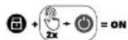
Switch-on procedure
Symbols on the cutting disc supplied

Read the instruction manual

Use eye protection

Use hearing protection

Use protective gloves

Use respiratory protection

Use foot protection

Do not use for side grinding

Use grinding disc only for dry grinding

Never use defective grinding discs

metal
General Power Tool Safety Warnings
⚠ WARNING! Read all safety warnings, instructions, illustrations and specifications provided with this power tool. Failure to follow all instructions listed below may result in electric shock, fire and/or serious injury. Save all warnings and instructions for future reference.
The term “power tool” in the warnings refers to your mains-operated (corded) power tool or battery-operated (cordless) power tool.
1. WORK AREA SAFETY
a) Keep work area clean and well lit. Cluttered or dark areas invite accidents.
b) Do not operate power tools in explosive atmospheres, such as in the presence of flammable liquids, gases or dust. Power tools create sparks which may ignite the dust or fumes.
c) Keep children and bystanders away while operating a power tool. Distractions can cause you to lose control.
2. ELECTRICAL SAFETY
a) Power tool plugs must match the outlet. Never modify the plug in any way. Do not use any adapter plugs with earthed (grounded) power tools. Unmodified plugs and matching outlets will reduce risk of electric shock.
b) Avoid body contact with earthed or grounded surfaces, such as pipes, radiators, ranges and refrigerators. There is an increased risk of electric shock if your body is earthed or grounded.
c) Do not expose power tools to rain or wet conditions. Water en-
tering a power tool will increase the risk of electric shock.
d) Do not abuse the cord. Never use the cord for carrying, pulling or unplugging the power tool. Keep cord away from heat, oil, sharp edges or moving parts. Damaged or entangled cords increase the risk of electric shock.
e) When operating a power tool outdoors, use an extension cord suitable for outdoor use. Use of a cord suitable for outdoor use reduces the risk of electric shock.
f) If operating a power tool in a damp location is unavoidable, use a residual current device (RCD) protected supply. Use of an RCD reduces the risk of electric shock.
3. PERSONAL SAFETY
a) Stay alert, watch what you are doing and use common sense when operating a power tool. Do not use a power tool while you are tired or under the influence of drugs, alcohol or medication. A moment of inattention while operating power tools may result in serious personal injury.
b) Use personal protective equipment. Always wear eye protection. Protective equipment such as a dust mask, non-skid safety shoes, hard hat or hearing protection used for appropriate conditions will reduce personal injuries.
c) Prevent unintentional starting. Ensure the switch is in the off-position before connecting to power source and/or battery pack, picking up or carrying the tool. Carrying power tools with your finger on the switch or energising power tools that have the switch on invites accidents.
d) Remove any adjusting key or wrench before turning the power tool on. A wrench or a key left attached to a rotating part of the power tool may result in personal injury.
e) Do not overreach. Keep proper footing and balance at all times. This enables better control of the power tool in unexpected situations.
f) Dress properly. Do not wear loose clothing or jewellery. Keep your hair and clothing away from moving parts. Loose clothes, jewellery or long hair can be caught in moving parts.
g) If devices are provided for the connection of dust extraction and collection facilities, ensure these are connected and properly used. Use of dust collection can reduce dust-related hazards.
h) Do not let familiarity gained from frequent use of tools allow you to become complacent and ignore tool safety principles. A careless action can cause severe injury within a fraction of a second.
4. POWER TOOL USE AND CARE
a) Do not force the power tool. Use the correct power tool for your application. The correct power tool will do the job better and safer at the rate for which it was designed.
b) Do not use the power tool if the switch does not turn it on and off. Any power tool that cannot be controlled with the switch is dangerous and must be repaired.
c) Disconnect the plug from the power source and/or remove the battery pack, if detachable, from the power tool before making any adjustments, changing
accessories, or storing power tools. Such preventive safety measures reduce the risk of starting the power tool accidentally.
d) Store idle power tools out of the reach of children and do not allow persons unfamiliar with the power tool or these instructions to operate the power tool. Power tools are dangerous in the hands of untrained users.
e) Maintain power tools and accessories. Check for misalignment or binding of moving parts, breakage of parts and any other condition that may affect the power tool's operation. If damaged, have the power tool repaired before use. Many accidents are caused by poorly maintained power tools.
f) Keep cutting tools sharp and clean. Properly maintained cutting tools with sharp cutting edges are less likely to bind and are easier to control.
g) Use the power tool, accessories and tool bits etc. in accordance with these instructions, taking into account the working conditions and the work to be performed. Use of the power tool for operations different from those intended could result in a hazardous situation.
h) Keep handles and grasping surfaces dry, clean and free from oil and grease. Slippery handles and grasping surfaces do not allow for safe handling and control of the tool in unexpected situations.
5. BATTERY TOOL USE AND CARE
a) Recharge only with the charger specified by the manufacturer.
A charger that is suitable for one type of battery pack may create a
risk of fire when used with another battery pack.
b) Use power tools only with specifically designated battery packs. Use of any other battery packs may create a risk of injury and fire.
c) When battery pack is not in use, keep it away from other metal objects, like paper clips, coins, keys, nails, screws or other small metal objects, that can make a connection from one terminal to another. Shorting the battery terminals together may cause burns or a fire.
d) Under abusive conditions, liquid may be ejected from the battery; avoid contact. If contact accidentally occurs, flush with water. If liquid contacts eyes, additionally seek medical help. Liquid ejected from the battery may cause irritation or burns.
e) Do not use a battery pack or tool that is damaged or modified. Damaged or modified batteries may exhibit unpredictable behaviour resulting in fire, explosion or risk of injury.
f) Do not expose a battery pack or tool to fire or excessive temperature. Exposure to fire or temperature above 130 °C may cause explosion.
g) Follow all charging instructions and do not charge the battery pack or tool outside the temperature range specified in the instructions. Charging improperly or at temperatures outside the specified range may damage the battery and increase the risk of fire.
6. SERVICE
a) Have your power tool serviced by a qualified repair person us-
ing only identical replacement parts. This will ensure that the safety of the power tool is maintained.
b) Never service damaged battery packs. Service of battery packs should only be performed by the manufacturer or authorized service providers.
Safety information for angle grinders
Safety warnings common for grinding, wire brushing and cutting-off operations
- This power tool is intended to function as a grinder, wire brush or cut-off tool. Read all safety warnings, instructions, illustrations and specifications provided with this power tool. Failure to follow all instructions listed below may result in electric shock, fire and/or serious injury.
- Operations such as sanding, polishing or hole cutting are not to be performed with this power tool. Operations for which the power tool was not designed may create a hazard and cause personal injury.
- Do not convert this power tool to operate in a way which is not specifically designed and specified by the tool manufacturer. Such a conversion may result in a loss of control and cause serious personal injury.
-
Do not use accessories which are not specifically designed and specified by the tool manufacturer. Just because the accessory can be attached to your power tool, it does not assure safe operation.
-
The rated speed of the accessory must be at least equal to the maximum speed marked on the power tool. Accessories running faster than their rated speed can break and fly apart.
- The outside diameter and the thickness of your accessory must be within the capacity rating of your power tool. Incorrectly sized accessories cannot be adequately guarded or controlled.
- The dimensions of the accessory mounting must fit the dimensions of the mounting hardware of the power tool. Accessories that do not match the mounting hardware of the power tool will run out of balance, vibrate excessively and may cause loss of control.
- Do not use a damaged accessory. Before each use inspect the accessory such as abrasive wheels for chips and cracks, backing pad for cracks, tear or excess wear, wire brush for loose or cracked wires. If power tool or accessory is dropped, inspect for damage or install an undamaged accessory. After inspecting and installing an accessory, position yourself and bystanders away from the plane of the rotating accessory and run the power tool at maximum no-load speed for one minute. Damaged accessories will normally break apart during this test time.
- Wear personal protective equipment. Depending on application, use face shield, safety goggles or safety glasses. As appropriate, wear dust mask, hearing protectors, gloves and workshop apron capable of stopping small abrasive or workpiece
fragments. The eye protection must be capable of stopping flying debris generated by various applications. The dust mask or respirator must be capable of filtrating particles generated by the particular application. Prolonged exposure to high intensity noise may cause hearing loss.
- Keep bystanders a safe distance away from work area. Anyone entering the work area must wear personal protective equipment. Fragments of workpiece or of a broken accessory may fly away and cause injury beyond immediate area of operation.
- Hold the power tool by insulated gripping surfaces only, when performing an operation where the cutting accessory may contact hidden wiring. Cutting accessories contacting a “live” wire may make exposed metal parts of the power tool “live” and could give the operator an electric shock.
- Never lay the power tool down until the accessory has come to a complete stop. The spinning accessory may grab the surface and pull the power tool out of your control.
- Do not run the power tool while carrying it at your side. Accidental contact with the spinning accessory could snag your clothing, pulling the accessory into your body.
- Regularly clean the power tool's air vents. The motor's fan will draw the dust inside the housing and excessive accumulation of powdered metal may cause electrical hazards.
- Do not operate the power tool near flammable materials. Sparks could ignite these materials.
- Do not use accessories that require liquid coolants. Using water or other liquid coolants may result in electrocution or shock.
Kickback and related warnings
Kickback is a sudden reaction to a pinched or snagged rotating wheel, backing pad, brush or any other accessory. Pinching or snagging causes rapid stalling of the rotating accessory which in turn causes the uncontrolled power tool to be forced in the direction opposite of the accessory's rotation at the point of the binding. For example, if an abrasive wheel is snagged or pinched by the workpiece, the edge of the wheel that is entering into the pinch point can dig into the surface of the material causing the wheel to climb out or kick out. The wheel may either jump toward or away from the operator, depending on direction of the wheel's movement at the point of pinching. Abrasive wheels may also break under these conditions.
Kickback is the result of power tool misuse and/or incorrect operating procedures or conditions and can be avoided by taking proper precautions as given below.
- Maintain a firm grip with both hands on the power tool and position your body and arms to allow you to resist kickback forces. Always use auxiliary handle, if provided, for maximum control over kickback or torque reaction during start-up. The operator can control torque reactions or kickback forces, if proper precautions are taken.
- Never place your hand near the rotating accessory. Accessory may kickback over your hand.
- Do not position your body in the area where power tool will move if kickback occurs. Kickback will propel the tool in direction opposite to the wheel's movement at the point of snagging.
- Use special care when working corners, sharp edges, etc. Avoid bouncing and snagging the accessory. Corners, sharp edges or bouncing have a tendency to snag the rotating accessory and cause loss of control or kickback.
- Do not attach a saw chain wood-carving blade, segmented diamond wheel with a peripheral gap greater than 10 mm or toothed saw blade. Such blades create frequent kickback and loss of control.
Safety warnings specific for grinding and cutting-off operations
- Use only wheel types that are specified for your power tool and the specific guard designed for the selected wheel. Wheels for which the power tool was not designed cannot be adequately guarded and are unsafe.
- The grinding surface of centre depressed wheels must be mounted below the plane of the guard lip. An improperly mounted wheel that projects through the plane of the guard lip cannot be adequately protected.
- The guard must be securely attached to the power tool and positioned for maximum safety, so the least amount of wheel is exposed towards the operator. The guard helps to protect the operator from broken wheel fragments,
accidental contact with wheel and sparks that could ignite clothing.
- Wheels must be used only for specified applications. For example: do not grind with the side of cut-off wheel. Abrasive cut-off wheels are intended for peripheral grinding, side forces applied to these wheels may cause them to shatter.
- Always use undamaged wheel flanges that are of correct size and shape for your selected wheel. Proper wheel flanges support the wheel thus reducing the possibility of wheel breakage. Flanges for cut-off wheels may be different from grinding wheel flanges.
- Do not use worn down wheels from larger power tools. A wheel intended for larger power tool is not suitable for the higher speed of a smaller tool and may burst.
- When using dual purpose wheels always use the correct guard for the application being performed. Failure to use the correct guard may not provide the desired level of guarding, which could lead to serious injury.
Additional safety warnings specific for cutting-off operations
- Do not “jam” the cut-off wheel or apply excessive pressure. Do not attempt to make an excessive depth of cut. Overstressing the wheel increases the loading and susceptibility to twisting or binding of the wheel in the cut and the possibility of kickback or wheel breakage.
- Do not position your body in line with and behind the rotating wheel. When the wheel, at the point of operation, is moving
away from your body, the possible kickback may propel the spinning wheel and the power tool directly at you.
- When the wheel is binding or when interrupting a cut for any reason, switch off the power tool and hold it motionless until the wheel comes to a complete stop. Never attempt to remove the cut-off wheel from the cut while the wheel is in motion otherwise kickback may occur. Investigate and take corrective action to eliminate the cause of wheel binding.
- Do not restart the cutting operation in the workpiece. Let the wheel reach full speed and carefully re-enter the cut. The wheel may bind, walk up or kickback if the power tool is restarted in the workpiece.
- Support panels or any oversized workpiece to minimize the risk of wheel pinching and kickback. Large workpieces tend to sag under their own weight. Supports must be placed under the workpiece near the line of cut and near the edge of the workpiece on both sides of the wheel.
- Use extra caution when making a “pocket cut” into existing walls or other blind areas. The protruding wheel may cut gas or water pipes, electrical wiring or objects that can cause kickback.
- Do not attempt to do curved cutting. Overstressing the wheel increases the loading and susceptibility to twisting or binding of the wheel in the cut and the possibility of kickback or wheel breakage, which can lead to serious injury.
Safety Warnings Specific for Wire Brushing Operations
- Be aware that wire bristles are thrown by the brush even during ordinary operation. Do not over-stress the wires by applying excessive load to the brush. The wire bristles can easily penetrate light clothing and/or skin.
- If the use of a guard is recommended for wire brushing, do not allow any interference of the wire wheel or brush with the guard. Wire wheel or brush may expand in diameter due to work load and centrifugal forces.
Additional safety instructions
- Never keep the fingers between the grinding disc and spark protection or in close proximity to the guard covers. There is a risk of crushing.
- The rotating parts of the device cannot be covered due to functional reasons. Therefore, proceed cautiously and secure the workpiece in order to avoid slipping which could cause your hands to come into contact with the grinding disc.
- The workpiece becomes hot during grinding. Do not touch the machined area, allow it to cool down. There is a risk of burns. Do not use coolants or the like.
- Do not work with the device if you are tired or have consumed alcohol or tablets. Always have a break on time.
- Switch off the device and remove the battery. Make sure that all moving parts have come to a complete stop:
• to loosen a blocked insertion tool
• in case of unusual sounds
- before checking the device, cleaning it or performing maintenance work on it
- Only use accessories recommended by PARKSIDE. Unsuitable accessories may cause electric shock or fire.
Residual risks
There will always be residual risks even if you operate this device according to the instructions. The following hazards may occur in connection with the type and design of this device:
- Eye damage if no suitable eye protection is worn.
- Lung damage if suitable respiratory protection is not worn.
- Hearing damage if suitable ear protection is not worn.
- Health injuries resulting from the effect of hand/arm vibration in the event that the tool is used over a longer period of time or is not used and maintained properly.
• Damage to health as a result of:
- touching the area of the grinding tool which is not covered;
- ejection of parts of workpieces or damaged grinding discs.
⚠ WARNING! Danger due to electromagnetic field generated while the tool is in operation. Under certain circumstances, this field may negatively affect active or passive medical implants. In order to reduce the danger of serious or fatal injuries, we recommend that individuals who wear medical implants should consult their doctor and the manufacturer of the implant before operating the tool.
Preparation
⚠ WARNING! Risk of injury due to unintentional start-up. Only insert the battery into the device once the device is fully prepared for use.
Control elements
Familiarise yourself with the operating elements before using the device for the first time.
Unlock button (13)
- The charge level indicator (11) on the control panel lights up.
- You can operate the tool until the charge level indicator goes out.
Speed button (14)
Switch speed level
- 1 ≧ lowest speed level
- 6 ≜ highest speed level
- The display (12) shows the selected speed level.
On/Off button (15)
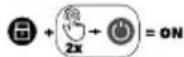
Switching on: Press the On/Off button twice in quick succession.
Switching off: Press the On/Off button or the Unlock button.
Spindle lock (8)
- Locks the spindle when attaching/ removing the attachment tool.
Fitting the auxiliary handle
⚠ WARNING! Loss of control can result in injuries! Only operate the machine with the auxiliary handle attached.
Procedure
- Turn the auxiliary handle (4) tightly into one of the holders (9) for the auxiliary handle.
The auxiliary handle can be attached to the tool in the following positions: top, left, right.
Attaching and removing the guard cover
Requirements
- Battery removed from device
- Attachment tool and mounting flange (27) removed
Fitting the guard cover (Fig. A)
-
Place the guard cover (5) on the tool so that the open side faces the tool. The recesses on the guard cover must fit into the grid (30) on the tool, only one position is possible.
-
Press and hold the release lever (31) of the guard cover towards the device.
-
Turn the guard cover (5) at least 14 turn.
-
Let go of the release lever (31).
-
Move the guard cover (5) a little until it clicks into place.
You can now fit an attachment tool.
Removing the guard cover (Fig. A)
-
Press the release lever underneath the guard cover (31) towards the tool and turn the guard cover (5) right until the open side of the guard cover faces the tool.
-
If the recesses on the guard cover match the grid (30) on the tool, then you can remove the guard cover (5) upwards.
Attaching and removing the attachment tool
Permissible attachment tool
⚠ WARNING! Risk of injury! Not any accessory that can be attached to your power tool assures safe opera-
tion. Do not use accessories which are not specifically designed and specified by the tool manufacturer.
⚠ WARNING! Risk of injury! Accessories running faster than their rated speed can break and fly apart. The rated rotational speed or circumferential speed of the accessory must be at least equal to that specified below.
All attachment tools
• Maximum speed: ≥10000 min ^-1
- diameter: ≤ 125 ~mm
Grinding disc
- Thickness: ≤ 6 mm
Cutting disc
- Thickness: ≤ 1.2 ~mm
- Cutting disk types: diamond studded, bonded reinforced, segmented
Disc brush
• Thickness: ≤16.5 mm
Cup brush
- Thickness: ≤ 5 mm
Attaching and removing the disc

⚠️ CAUTION! Risk of injury when touching the attachment tool. Wear protective gloves when handling the attachment tool.
Notes
- DANGER! Risk of injury! Only use attachment tools recommended by the manufacturer.
- Only use undamaged attachment tools.
-
The disc is attached with a keyless chuck (26) to the uptake spindle (28). There are two ways to loosen or tighten the keyless chuck:
-
By hand: To do this, fold the bracket (25) of the keyless chuck upwards.
- With the chuck key (16); kept in the auxiliary handle (4)
Procedure (Fig. C)
- Check the attachment tool. Do not use the attachment tool if it is damaged.
- Press and hold the spindle lock (8).
- Turn the uptake spindle (28) until the stop button holds the uptake spindle in a fixed position. Keep pressing the spindle lock (8).
- Loosen the keyless chuck (26). You can release the spindle lock (8).
- Disassembly: Take the attachment tool off the mounting flange (27).
Assembly: Place the attachment tool on the mounting flange (27).
The label on the cutting/grinding disc should always face the tool. If a direction of rotation is indicated on the disc, this must match the direction of rotation arrow (7)
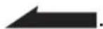
Ensure that the attachment flange (27) is placed on the tool in such a way that the recesses in the attachment flange grip into the edge of the tool. The uptake spindle (28) must turn simultaneously when you turn the attachment flange.
- Place the keyless chuck (26) on the uptake spindle (28). The flat side of the keyless chuck faces the attachment tool.
- Press and hold the spindle lock (8).
- Turn the uptake spindle (28) until the stop button holds the uptake spindle in a fixed position. Keep pressing the spindle lock (8).
- Tighten the keyless chuck (26).
You can release the spindle lock (8).
If you have fitted a cutting disc: Fit the attachment onto the guard cover (p. 46).
Fitting and removing the wire brush

⚠️ CAUTION! Risk of injury when touching the attachment tool. Wear protective gloves when handling the attachment tool.
Tools required
- Open-end spanner (not included)
Removing the wire brushes (Fig. D)
- Press and hold the spindle lock (8).
- Turn the uptake spindle (28) until the stop button holds the uptake spindle in a fixed position. Keep pressing the spindle lock (8).
- Release the wire brush with an open-end spanner.
You can release the spindle lock (8).
Fitting the wire brush (Fig. D)
- Place the desired wire brush onto the uptake spindle (28).
- Press and hold the spindle lock (8).
- Turn the wire brush onto the up-take spindle (28). Tighten the wire brush using a combination wrench.
You can release the spindle lock (8).
Fitting and removing the attachment on the guard cover

⚠️ CAUTION! Risk of injury when touching the attachment tool. Wear protective gloves when handling the attachment tool.
Requirements
- Cutting disc mounted
- Battery removed from device
Fitting the attachment (17) (Fig. B)
- Place the attachment (17) on the guard cover (5) and turn the attachment (17) until it audibly clicks into place.
Removing the attachment (17) (Fig. B)
- Release one of the two locks (18) on the attachment (17) by pushing the lock (18) outwards.
- Slide the released lock (18) over the guard cover (5) until the attachment is removed after half a turn.
Checking the battery charge level
LEDs Meaning
red, orange, green Battery charged
red, orange Battery partially charged
red Battery needs to be charged
At the battery
- Press the button (21) next to the charge level indicator button (20) on the battery (22). The LEDs of the charge level indicator show how much charge remains in the battery.
- Charge the battery (22) when only the red LED on the charge level indicator (20) is illuminated.
At the tool
- The charge level indicator (11) lights up during operation. If the charge level indicator does not light up, press the Unlock button (13).
The LEDs of the charge level indicator show how much charge remains in the battery.
- Charge the battery (22) when only the red LED on the charge level indicator (11) is illuminated.
Charging the battery
See also the charger instruction manual.
Notes
- If warm, allow the battery to cool before charging.
- Do not expose the battery to direct sunlight for long periods and do not place it on a radiator (max. 50°C).
Procedure
- If necessary, remove the battery (22) from the cordless device.
- Slide the battery (22) into the charging slot (24) of the charger (23).
- Plug the charger (23) into an power outlet.
- Once charging is complete, disconnect the charger (23) from the mains supply.
- Pull the battery (22) charging slot out (24).
Control LEDs on the charger (23):
| green red | Meaning | |
| lights up | — • Battery is fully charged• stand-by (No battery inserted) | |
| — lights up | Battery is charging | |
| — flashes | Battery is over-heated | |
| flashes flashes | Battery is defective | |
Operation
Working instructions
- ⚠ WARNING! Risk of injury! If possible, use clamps to hold the workpiece in place. Never hold a small workpiece in one hand and the device in the other while using the device.
- DANGER! Risk of injury! Ensure that you have sufficient space in which to work, and that you do not endanger other people.
- Adjust the guard cover such that any sparks or detached parts cannot hit either the user or any bystanders.
The guard cover must also be positioned such that the sparks cannot ignite combustible parts, including those in the surroundings.
- The power tool must not be used with a cutting stand.
- Only switch on the device when the attachment tool is not touching the workpiece.
- Excessive pressure reduces the performance of the power tool and leads to faster wear of the attachment tool.
- Always work in the counter-direction. This ensures that the device is not pushed out of the cut through lack of control.
The direction of rotation arrow (7) symbolises the running direction of the attachment tool.
- After a heavy load, let the device idle for a few minutes to cool down the attachment tool.
- Do not touch the attachment tool until it has cooled down.
Trial run
Always carry out a trial run without a load before carrying out your first
procedure as well as after every tool change. Switch the tool off immediately if the tool is not rotating smoothly, if considerable vibration occurs, or if you hear abnormal noises.
Abrasive cutting
Requirements
- Cutting disc NOTICE! Property damage. Never use a roughing disc for cutting!
• diameter ≤125 mm - Cutting disk types: diamond studded, bonded reinforced, segmented
- Attachment (17) mounted on guard cover (5)
Notes
- In general, work with a low feed rate. Exert only moderate pressure on the work-piece.
Information on building statics
Slits in structural walls are subject to the country-specific regulations. These regulations must be observed without fail.
Before beginning work you should ask the structural engineer, architect or relevant construction supervisor for advice.
Roughing
Requirements
- Roughing wheel NOTICE! Property damage. Never use a cutting disc for roughing!
• diameter ≤125 mm - Thickness ≤ 6 mm
- Guard cover without attachment
⚠ WARNING! Risk of injury due to loss of control. Remove the attachment (17) of the guard cover (5) to avoid bumping the workpiece.
Notes
- In general, work with a low feed rate. Exert only moderate pressure on the work-piece.
- A working angle of 30^ to 40^ achieves the best results for roughing.
Grinding with a wire brush
Requirements
- Suitable grinding brush
- Guard cover (5)
Notes
- Wear safety goggles as wires could come loose.
- Only use disc brushes that are no thicker than the maximum permitted thickness ( ≤ 16.5 mm). Wires can hit the guard cover and break.
- Suitable for rough rust removal, cleaning weld seams and removing paint.
- Exert only moderate pressure on the workpiece. Do not exert excessive strain on the wire brush by pressing down too hard.
Inserting and removing the battery
⚠ WARNING! Risk of injury due to unintentional start-up. Only insert the battery into the device once the device is fully prepared for use.
NOTICE! Risk of damage! An incorrect battery can damage the device and battery.
Inserting the battery
- Push the battery (22) along the guide into the battery holder (2). You will hear the battery click into place.
Removing the battery
-
Press and hold the battery release (19) on the battery (22).
-
Pull the battery out of the battery holder (2).
Adjusting the guard cover
⚠ WARNING! Risk of injury due to unintentional start-up. Remove the battery (22) from the device.

⚠️ CAUTION! Risk of injury when touching the attachment tool. Wear protective gloves when handling the attachment tool.
Notes
- Adjust the guard cover (5) so that any sparks or detached parts cannot hit either the user or any bystanders.
- Position the guard cover (5) so that the sparks do not ignite any combustible parts, including those in the surroundings.
Procedure (Fig. A)
- Press and hold the release lever (31) of the guard cover towards the device.
- Turn the guard cover (5) into the desired position.
- Let go of the release lever (31).
- Move the guard cover (5) a little until it clicks into place.
Adjusting the speed
You can adjust the speed at any time during operation. Use the speed button (14) to select the desired level.
Rough guide for speed selection:
| level | Attachment tool | Application |
| 2-3 Cup brush Brushing, coarse rust removal, paint removal | ||
| 4-6 Grinding disc Sanding/Grinding | ||
| 6 Grinding disc Roughing | ||
| 6 Cutting disc Cutting | ||
Switching on and off
Notes
- Depending on the intended use, observe the working instructions for the device (Working instructions, p. 47).
- When the guard cover is fitted, adjust it so that the smallest possible part of the grinder is facing the operator. Readjust the guard cover if necessary.
Switching on
- Press the Unlock button (13). The charge level indicator (11) in the control panel lights up.
- Select a suitable speed. You can adjust the speed at any time during operation.
- Switch on: Press the On/Off button (15) twice in quick succession.
- Check that the attachment tool is running smoothly. If not: Replace the attachment tool.
- Wait until the device has reached full speed.
- Guide the attachment tool against the workpiece.
Switching off
- Remove the attachment tool from the workpiece.
- Switch off: Press the On/Off button (15) or the Unlock button (13).
The charge level indicator (11) in the control panel goes out.
- Wait until the power tool has stopped before placing it down.
- If you are leaving the device un-attended or if you have finished working: Remove the battery (22) from the device.
PARKSIDE app
The PARKSIDE app lets you monitor the device and control certain functions. The functions may change with updates to the app and firmware. For more information on the PARKSIDE app, see the instructions for the smart battery.
Requirements
To find the device in the PARKSIDE app, the following requirements must be met:
- The PARKSIDE app is installed on your smartphone and Bluetooth® is activated.
- The following battery is inside the device: PARKSIDE Performance Smart battery PAPS 204 A1 or PAPS 208 A1. This battery is already connected to the PARKSIDE app.
The device communicates with the app via the battery.
Connecting the device to the PARKSIDE app
- Insert the smart battery (22).
-
Press the Unlock button (13). The “Connected” display (10) flashes three times. When the device is connected, the “Connected” indicator lights up continuously.
-
Open the PARKSIDE app.
-
Your tools.
The device is displayed in the list.
If the device does not appear in the list, add the device manually.
Monitoring and controlling the device
-
Your tools.
-
Select the device from the list. The device overview page is displayed.
- Select the desired setting on the overview page.
Select help if you are unsure. A dialogue box with a description for the relevant setting is displayed.
Cleaning, maintenance and storage
⚠ WARNING! Risk of injury due to unintentional start-up. Protect yourself when performing maintenance or cleaning work. Switch off the device and remove the battery (22). You should have any repair and maintenance work that is not described in these instructions carried out by our Service Centre. Only use original replacement parts.
Cleaning
⚠ WARNING! Electric shock! Never spray down the device with water. NOTICE! Risk of damage. Chemical substances may attack the plastic parts of the machine. Do not use any cleaning agents or solvents.
- Keep the ventilation slits, motor housing and handles of the machine clean. Use a damp cloth or brush to do this.
Cleaning the dust protection grille (Fig. E)
- Clean the dust protection grille (3) with a brush.
- You can remove the dust protection grille for thorough cleaning. To do this, insert a narrow slotted screwdriver at the marked point. Replace a defective dust protection grille (Spare parts and accessories, p. 55).
Maintenance
The device is maintenance free.
Storage
Always store the device and accessories:
- clean
- dry
• protected against dust
• In the case provided (29)
• out of the reach of children
The storage temperature for the rechargeable battery and the device is between 0 °C and 45 °C. Avoid extreme cold or heat during storage to ensure the battery output is not adversely affected.
Remove the rechargeable battery from the device before storing the device (see the separate operating instructions for the battery and charger).
Storing cutting/grinding discs
- dry
- upright
- unstacked
Troubleshooting
The following table will assist you in fixing faults:
| Problem Possible cause | Error correction | |
| Device does not start | Rechargeable battery (22) not inserted | Inserting the battery, p. 48 |
| On/Off button (15) defective | Contact the service centre. | |
| Defective motor Contact the service centre. | ||
| Attachment tool does not move although motor is running | Clamping nut (26) loose Tightening the clamping nut | |
| Workpiece, workpiece remnants or remnants of attachment tools blocking the drive | Remove blockages | |
| Engine is slowing down and stops | Device is overloaded through workpiece | Reduce pressure on attachment tool |
| Workpiece unsuitable | ||
| Attachment tool does not rotate smoothly, abnormal noises can be heard | Clamping nut (26) loose Tightening the clamping nut | |
| Attachment tool defective | Changing the attachment tool | |
| Problem Possible cause Error correction | ||
| Device works with inter- rptions | Internal loose contact | Contact the service centre. |
| On/Off button (15) defect- ive | ||
Transport
Notes
- Turn off the device.
• Make sure that all moving parts have come to a complete stop. - Remove the rechargeable battery.
- Remove the attachment tool.
• Always carry the device by the handle (1).
Disposal/ environmental protection
Remove the battery from the device and recycle the device, battery, accessories and packaging in an environmentally-friendly manner.
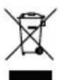
Waste electrical and electronic equipment (WEE) must not be disposed of with domestic waste.
The symbol of the crossed-out wheeled bin means that this product must not be disposed of as unsorted municipal waste at the end of its useful life.
Directive 2012/19/EU on waste electrical and electronic equipment:
Consumers are legally obliged to recycle electrical and electronic equipment in an environmentally sound manner at the end of its life. In this way, environmentally friendly and resource-saving recycling is ensured.
Depending on the implementation in national law, you may have the following options:
- Return to a shop,
- Hand over to an official collection point,
- Return to the manufacturer/distributor.
This does not affect accessories enclosed with the old devices or tools without any electrical components.
Disposal instructions for rechargeable batteries
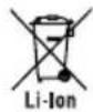
Do not throw batteries into domestic waste, fire (risk of explosion) or water. Damaged batteries can harm the environment and your health if poisonous fumes or liquids escape.
Dispose of the batteries according to local standards. Defective or used batteries must be recycled. Hand in the batteries at a used battery collection point where they are recycled in an environmentally friendly manner. For more information, please contact your local waste management provider or our service centre. Dispose of batteries in a discharged state. We recommend covering the contacts with an adhesive strip to protect against short circuits. Do not open the battery.
Service
Guarantee
Dear Customer,
This product is provided with a 5 year guarantee from the date of purchase. In case of defects, you have statutory rights against the seller of the product. These statutory rights are not restricted by our guarantee presented below.
Terms of Guarantee
The guarantee period begins on the date of purchase. Please retain the original receipt. This document is required as proof of purchase. If a material or manufacturing defect occurs within five years of the date of purchase of this product, we will repair or replace – at our choice – the product for you free of charge. This guarantee requires the defective product and proof of purchase to be presented within the five-year period with a brief written description of what constitutes the defect and when it occurred. If the defect is covered by our guarantee, you will receive either the repaired product or a new product. No new guarantee period begins on repair or replacement of the product.
Guarantee Period and Statutory Claims for Defects
The guarantee period is not extended by the guarantee service. This also applies for replaced or repaired parts. Any damages and defects already present at the time of purchase must be reported immediately after unpacking. Repairs arising after expiry of the guarantee period are chargeable.
Guarantee Cover
The product has been carefully produced in accordance with strict quality guidelines and conscientiously checked prior to delivery.
The guarantee applies for all material and manufacturing defects. This guarantee does not extend to cover product parts that are subject to normal wear and may therefore be considered as wearing parts (e.g. Cutting disc) or to cover damage to breakable parts.
This guarantee shall be invalid if the product has been damaged, used incorrectly or not maintained. Precise adherence to all of the instructions specified in the operating manual is required for proper use of the product. Intended uses and actions against which the operating manual advises or warns must be categorically avoided.
The product is designed only for private and not commercial use. The guarantee will be invalidated in case of misuse or improper handling, use of force, or interventions not undertaken by our authorised service branch.
Processing in Case of Guarantee
To ensure efficient handling of your query, please follow the directions below:
- Please have the receipt and product number (IAN 458760_2401) ready as proof of purchase for all enquiries.
- Please refer for the product number to the type plate on the product, an engraving on the product, the title page of the operating instructions (bottom left) or the sticker on the back or underside of the product.
- Should functional errors or other defects occur, please initially contact the service centre specified below by telephone or use
the contact form available on parkside-diy.com in the category Service.
- After consultation with our customer service, a product recorded as defective can be sent postage paid to the service address communicated to you, with the proof of purchase (receipt) and specification of what constitutes the defect and when it occurred. In order to avoid acceptance problems and additional costs, please be sure to use only the address communicated to you. Ensure that the consignment is not sent carriage forward or by bulky goods, express or other special freight. Please send the appliance inc. all accessories supplied at the time of purchase and ensure adequate, safe transport packaging.

You can view and download these and many other manuals on parkside-diy.com. This QR code will take you directly to parkside-diy.com. Select your country and search for the operating instructions via the search mask. You can open your operating instructions by entering the article number (IAN) 458760_2401.
Repair service
For repairs that are not covered by warranty, contact the service centre. They will gladly create a cost estimate for you.
• We can only work on devices which are sent in properly packed and with postage paid.
Note: Please send your device cleaned and with an indication of the defect to the address named for the service centre.
- The following are not accepted: devices sent in without prepaid postage, sent as bulky goods, sent as an Express shipment, or devices sent as any other form of special freight.
- We will dispose of defective devices you ship to us free of charge.
Service Centre
GB Service Great Britain Tel.: 0800 051 8970 Contact form on parkside-diy.com IAN 458760_2401
MT Service Malta Tel.: 800 65168 Contact form on parkside-diy.com IAN 458760_2401
Importer
Please note that the address below is not a service address. Contact the service centre named above first.
Spare parts and accessories
You can get spare parts and accessories from www.grizzlytools.shop. If you have any problems with your order, contact us via our online shop. If you have any other questions, contact: Service Centre, p. 54
Pos. nr. Name Order No.
| 3 Dust protection grille 91110524 |
| 4 Auxiliary handle 91110062 |
| 5 Guard cover 91110061 |
| 6 Cutting disc (A24 Q BF) 30211107 |
| 16 Chuck key 91110063 |
| 26+27 Clamping nut + Mounting flange 91110060 |
Also available
Name Order No.
Roughing wheel 91103235
Translation of the original EC declaration of conformity
Product: Cordless Angle Grinder
Model: PWSAP 20-Li F6
Serial number: 000001 - 341000
The object of the declaration described above is in conformity with the relevant Union harmonisation legislation:
2006/42/EC • 2014/30/EU • 2011/65/EU & (EU) 2015/863
Product with battery Smart PAPS 204 A1/Smart PAPS 208 A1: 2014/53/EU
The object of the declaration described above is in conformity with Directive 2011/65/EU of the European Parliament and of the Council of 8 June 2011 on the restriction of the use of certain hazardous substances in electrical and electronic equipment.
To ensure conformity, the following harmonised standards and national standards and regulations have been applied:
EN 62841-1:2015/A11:2022• EN IEC 62841-2-3:2021/A11:2021
EN IEC 55014-1:2021 • EN IEC 55014-2:2021
EN IEC 63000:2018
Product with battery Smart PAPS 204 A1/Smart PAPS 208 A1:
EN 301 489-1 V2.2.3:2019 • Draft EN 301 489-17 V3.2.6:2023
EN 300 328 V2.2.2:2019 • EN 50663:2017
This declaration of conformity is issued under the sole responsibility of the manufacturer:


Authorised representative of documentation
Sommaire
Introduction......57
Bride support .....∅22,23 mm Filetage .....M14
PDF ONLINE parkside-diy.com
- BEZPIECZEŃSTWO W MIEJSCU PRACY
Reparationsservice......298
Service-Center 299
Importør......299
natural_image
Close-up of a mechanical device with a handle and labeled part (3), no visible text or symbols beyond the number.Explosionszeichnung • Exploded view • Vue éclatée • Vista esplosa • Vista explosionada • Explosietekening • Eksploderet tegning • Robbantott ábra • Widok rozłożony • Rozložený pohled • Rozložený pohlád
PWSAP 20-Li F6
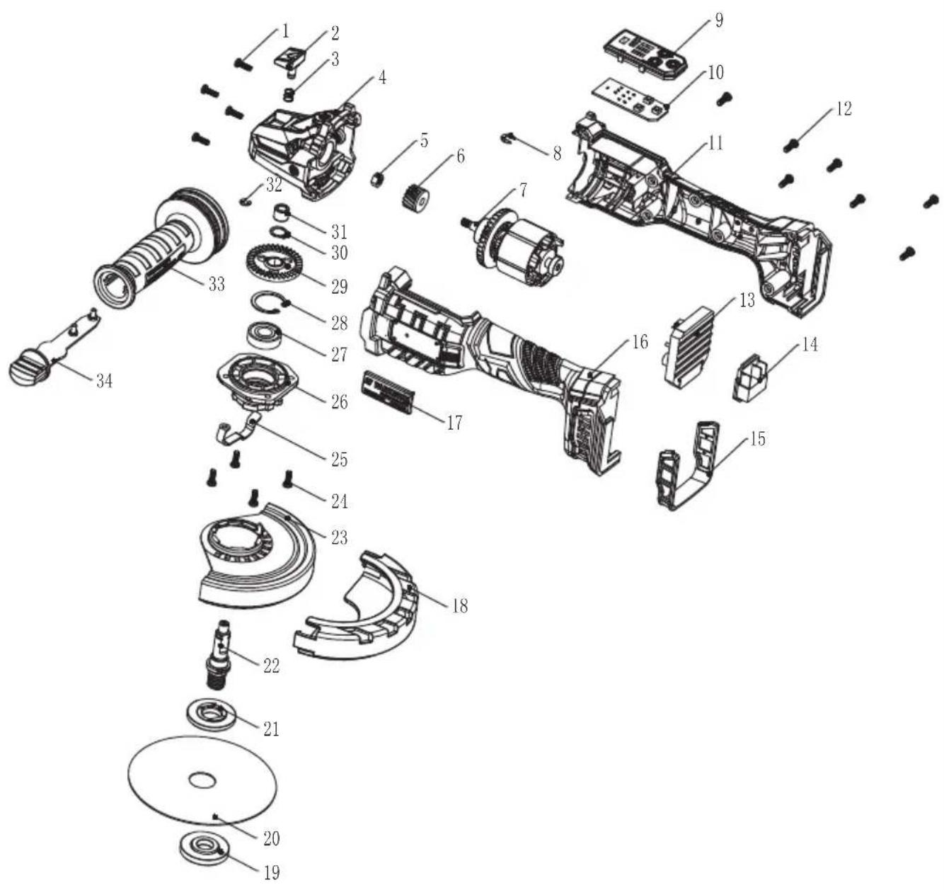
informativ • informative • informatif • informatief • informativo • informatív • informacyjny • informační • informatívny

GRIZZLY TOOLS GMBH & CO. KG


- Akku-Winkelschleifer / Cordless Angle Grinder / Meuleuse d'angle sans fil PWSAP 20-Li F6
- Cordless Angle Grinder
- Accu-haakse slijpmachine
- FR BE
- Inhaltsverzeichnis
- Einleitung......4
- Introduction......32
- Safety information.... 35
- Preparation......44
- Operation......47
- Parkside app.... 50
- Cleaning, maintenance and storage....50
- Troubleshooting....51
- Transport.... 52
- Disposal/environmental protection....52
- Service....53
- Spare parts and accessories......55
- Translation of the original EC declaration of conformity....56
- Exploded view....303
- Introduction
- Proper use
- Scope of delivery/ accessories
- The rechargeable battery and charger are not included in delivery.
- Overview
- Fig. A
- Description of functions
- Technical data
- Cutting disc ......A24 Q BF
- Charging time
- Safety information
- Meaning of the safety information
- Pictograms and symbols
- Symbols used in the instruction manual
- Symbols on the device
- Symbols on the cutting disc supplied
- General Power Tool Safety Warnings
- WORK AREA SAFETY
- ELECTRICAL SAFETY
- PERSONAL SAFETY
- POWER TOOL USE AND CARE
- BATTERY TOOL USE AND CARE
- Safety information for angle grinders
- Safety warnings common for grinding, wire brushing and cutting-off operations
- Kickback and related warnings
- Safety warnings specific for grinding and cutting-off operations
- Additional safety warnings specific for cutting-off operations
- Safety Warnings Specific for Wire Brushing Operations
- Additional safety instructions
- Residual risks
- Preparation
- Control elements
- Unlock button (13)
- Speed button (14)
- On/Off button (15)
- Spindle lock (8)
- Fitting the auxiliary handle
- Procedure
- Attaching and removing the guard cover
- Requirements
- Fitting the guard cover (Fig. A)
- Removing the guard cover (Fig. A)
- Attaching and removing the attachment tool
- Permissible attachment tool
- All attachment tools
- Grinding disc
- Cutting disc
- Disc brush
- Cup brush
- Attaching and removing the disc
- Notes
- Procedure (Fig. C)
- Fitting and removing the wire brush
- Tools required
- Removing the wire brushes (Fig. D)
- Fitting the wire brush (Fig. D)
- Fitting and removing the attachment on the guard cover
- Fitting the attachment (17) (Fig. B)
- Removing the attachment (17) (Fig. B)
- Checking the battery charge level
- LEDs Meaning
- At the battery
- At the tool
- Charging the battery
- Operation
- Working instructions
- Trial run
- Abrasive cutting
- Information on building statics
- Roughing
- Grinding with a wire brush
- Inserting and removing the battery
- Inserting the battery
- Removing the battery
- Adjusting the guard cover
- Procedure (Fig. A)
- Adjusting the speed
- Switching on and off
- Switching on
- Switching off
- PARKSIDE app
- Connecting the device to the PARKSIDE app
- Monitoring and controlling the device
- Cleaning, maintenance and storage
- Cleaning
- Cleaning the dust protection grille (Fig. E)
- Maintenance
- Storage
- Storing cutting/grinding discs
- Troubleshooting
- Transport
- Disposal/ environmental protection
- Directive 2012/19/EU on waste electrical and electronic equipment:
- Disposal instructions for rechargeable batteries
- Service
- Guarantee
- Terms of Guarantee
- Guarantee Period and Statutory Claims for Defects
- Guarantee Cover
- Processing in Case of Guarantee
- Repair service
- Service Centre
- Importer
- Spare parts and accessories
- Also available
- Name Order No.
- Translation of the original EC declaration of conformity
- Sommaire
- Introduction......57
- Explosionszeichnung • Exploded view • Vue éclatée • Vista esplosa • Vista explosionada • Explosietekening • Eksploderet tegning • Robbantott ábra • Widok rozłożony • Rozložený pohled • Rozložený pohlád
- GRIZZLY TOOLS GMBH & CO. KG
Brand : PARKSIDE
Model : PWSAP 20-Li F6
Category : Cordless angle grinder