JR003G - Saw MAKITA - Free user manual and instructions
Find the device manual for free JR003G MAKITA in PDF.

User questions about JR003G MAKITA
0 question about this device. Answer the ones you know or ask your own.
Ask a new question about this device
Download the instructions for your Saw in PDF format for free! Find your manual JR003G - MAKITA and take your electronic device back in hand. On this page are published all the documents necessary for the use of your device. JR003G by MAKITA.
USER MANUAL JR003G MAKITA
| EN | Cordless Recipro Saw INSTRUCTION MANUAL 6 | |
| FR | Scie Recipro sans Fil MANUEL D’INSTRUCTIONS 13 | |
| DE | Akku Reciprosäge BETRIEBSANLEITUNG 21 | |
| IT | Seghetto diritto a batteria ISTRUZIONI PER L’USO 29 | |
| NL | Accureciprozaag GEBRUIKSAANWIJZING 37 | |
| ES | Sierra Recíproca Inalámbrica | MANUAL DE INSTRUCCIONES 45 |
| PT | Serra Sabre a Bateria MANUAL DE INSTRUÇÕES 53 | |
| EL | Παλινδρομικό πριόνι μπαταρίας | ΕΓΧΕΙΡΙΔΙΟ ΟΔΗΓΙΩΝ 61 |
| TR | Akülü Kılıç Testere KULLANMA KILAVUZU 70 | |
JR003G
natural_image
Technical line drawing of a mechanical device with chain link and lever mechanism (no text or symbols)
text_image
Technical diagram showing a device with labeled parts and a zoomed-in view of the internal components.Fig.1
text_image
2 1 B 2 A 1 Fig.4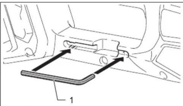
natural_image
Technical line drawing of a vehicle seat assembly with labeled component '1' (no text or symbols beyond label)Fig.5
text_image
Diagram showing a device with labeled components, including a battery and a control panel.Fig.2
text_image
1 2 3 4 Fig.6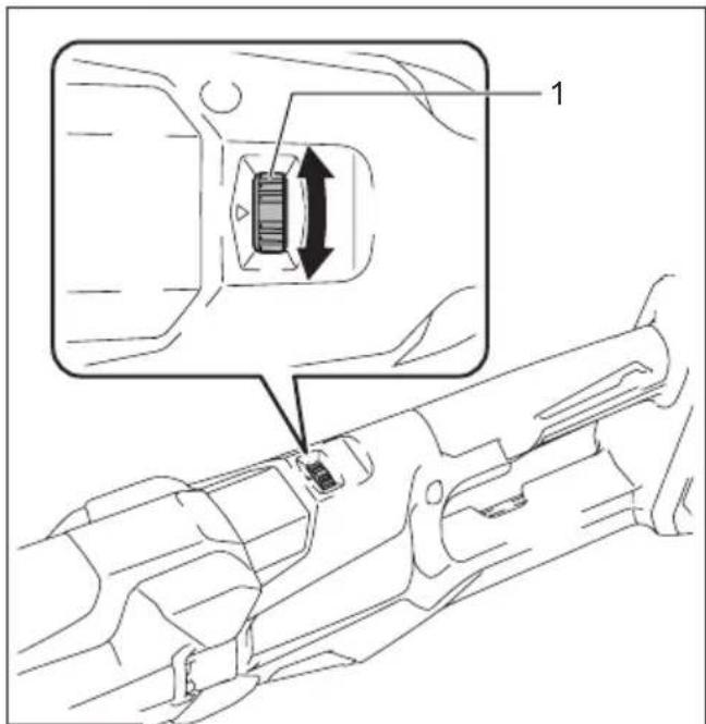
text_image
Technical diagram showing a component being inserted into a firearm, with labeled parts and directional arrows indicating movement.Fig.3
text_image
2 3 4 1 6 5 c Fig.7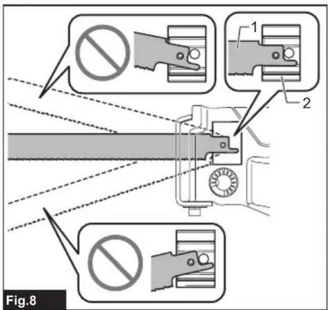
text_image
Fig.8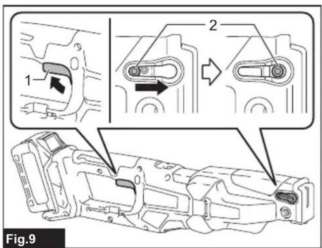
text_image
1 2 Fig.9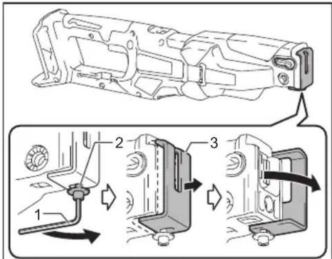
text_image
Technical diagram showing mechanical assembly steps with numbered components and directional arrows indicating motion or movement.Fig.10
text_image
1 2 3 Fig.11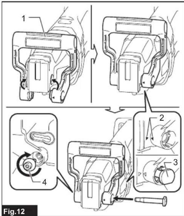
text_image
1 2 3 4 Fig.12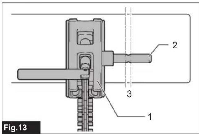
text_image
Fig.13 1 2 3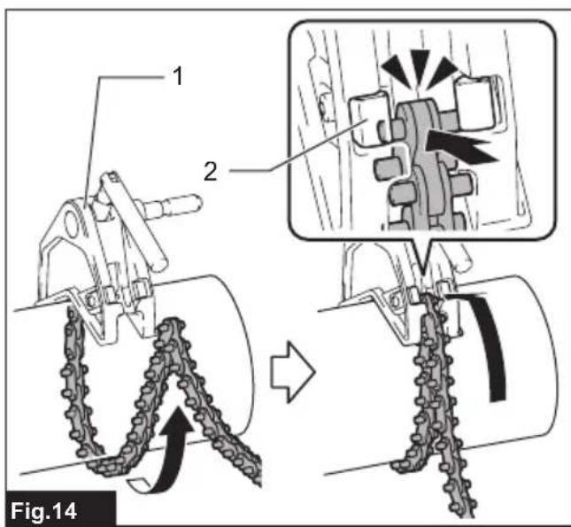
text_image
1 2 Fig.14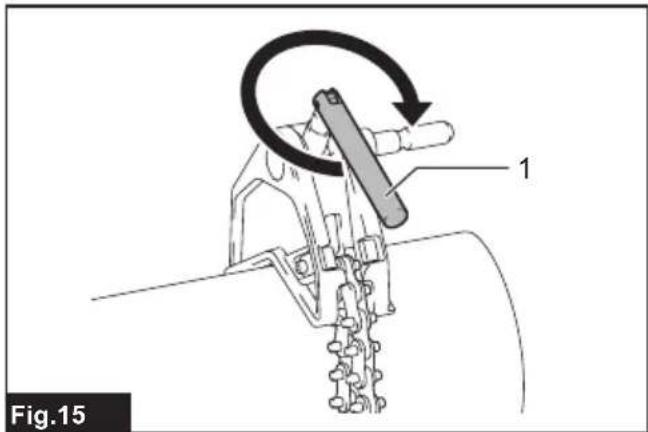
text_image
Fig.15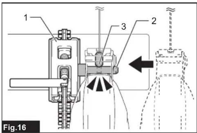
text_image
1 2 3 Fig.16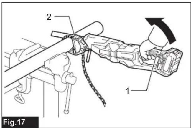
text_image
Fig.17 1 2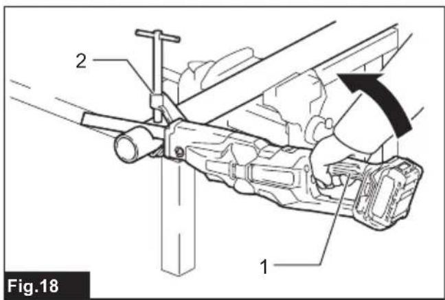
text_image
Fig.18 1 2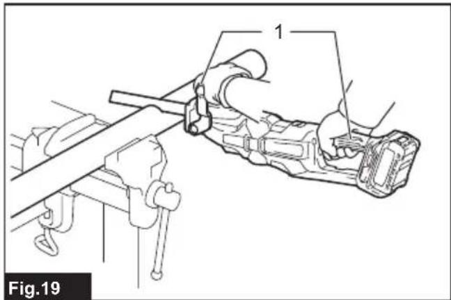
natural_image
Technical line drawing of a mechanical assembly with labeled components (no text or symbols present)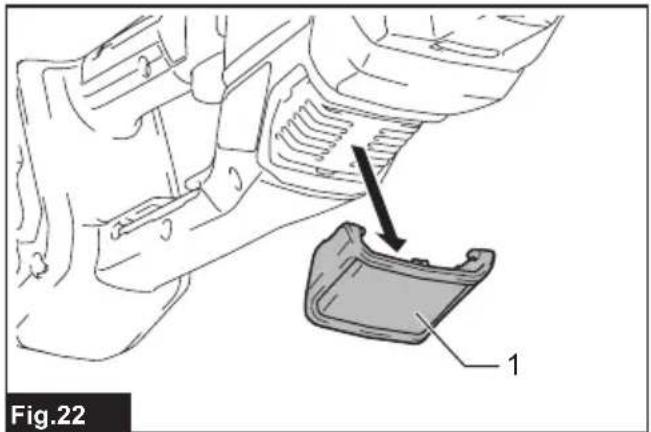
text_image
Fig.22 1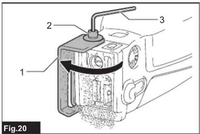
text_image
1 2 3 Fig.20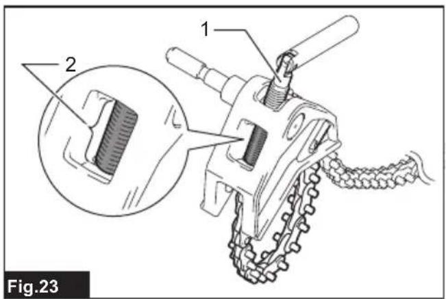
text_image
Fig.23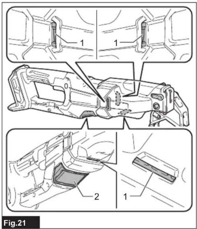
text_image
Fig.21SPECIFICATIONS
| Model: JR003G | ||
| Length of stroke 26 mm | ||
| Strokes per minute 0 - 2,200 min | -1 | |
| Max. cutting capacities (with chain vise) | Cast iron pipe (with mortar lining): (using 280mm diamond blade) | 169 mm |
| Cast iron pipe (without mortar lining) | 220 mm | |
| Iron pipe 220 mm | ||
| Steel pipe 220 mm | ||
| Max. cutting capacities (without chain vise): (using thin recipro saw blade) | Pipe 130 mm | |
| Wood (using 300mm thin recipro saw blade) | 255 mm | |
| Overall length (with BL4040) 583 mm | ||
| Rated voltage D.C. 36 V - 40 V max | ||
| Net weight 4.5 - 6.8 kg | ||
- Due to our continuing program of research and development, the specifications herein are subject to change without notice.
- Specifications and battery cartridge may differ from country to country.
- The net weight value includes the lightest and heaviest combination of the attachment(s) for normal and safe use and battery cartridge(s) which are specified in the instruction manual.
Applicable battery cartridge and charger
| Battery cartridge BL4020* / BL4025* / BL4040* / BL4050F* / BL4080F | *: Recommended battery |
| Charger DC40RA / DC40RB / DC40RC / DC40WA / BCC01 / BCC02 |
- Some of the battery cartridges and chargers listed above may not be available depending on your region of residence.
WARNING: Only use the battery cartridges and chargers listed above. Use of any other battery cartridges and chargers may cause injury and/or fire.
Intended use
The tool is intended for sawing wood, plastic and ferrous materials.
Noise
The typical A-weighted noise level determined according to EN62841-2-11:
Sound pressure level ( L_pA ): 82 dB (A)
Sound power level ( L_WA ): 90 dB (A)
Uncertainty (K) : 3 dB (A)
NOTE: The declared noise emission value(s) has been measured in accordance with a standard test method and may be used for comparing one tool with another.
NOTE: The declared noise emission value(s) can also be used in a preliminary assessment of exposure.
WARNING: Wear ear protection.
⚠ WARNING: The noise emission during actual use of the power tool can differ from the declared total value(s) depending on the ways in which the tool is used.
WARNING: Be sure to identify safety measures to protect the operator that are based on an estimation of exposure in the actual conditions of use (taking account of all parts of the operating cycle such as the times when the tool is switched off and when it is running idle in addition to the trigger time).
Vibration
The continuous vibration total value (tri-axial vector sum) determined according to EN62841-2-11:
Work mode: cutting boards
Vibration emission (a_h,B) : 14.9m / s^2
Uncertainty (K) : 1.6 m/s ^2
Work mode: cutting wooden beams Vibration emission ( a_h,WB ) 15.3 m/s ^2 Uncertainty (K) : 1.8 m/s ^2
NOTE: The declared vibration total value(s) has been measured in accordance with a standard test method and may be used for comparing one tool with another. NOTE: The declared vibration total value(s) can also be used in a preliminary assessment of exposure.
⚠ WARNING: The vibration emission during actual use of the power tool can differ from the declared total value(s) depending on the ways in which the tool is used.
WARNING: Be sure to identify safety measures to protect the operator that are based on an estimation of exposure in the actual conditions of use (taking account of all parts of the operating cycle such as the times when the tool is switched off and when it is running idle in addition to the trigger time).
Declarations of Conformity
For European countries only
The Declarations of conformity are included in Annex A to this instruction manual.
SAFETY WARNINGS
General power tool safety warnings
WARNING Read all safety warnings, instructions, illustrations and specifications provided with this power tool. Failure to follow all instructions listed below may result in electric shock, fire and/or serious injury.
Save all warnings and instructions for future reference.
The term "power tool" in the warnings refers to your mains-operated (corded) power tool or battery-operated (cordless) power tool.
Cordless recipro saw safety warnings
- Hold the power tool by insulated gripping surfaces, when performing an operation where the cutting accessory may contact hidden wiring. Cutting accessory contacting a "live" wire may make exposed metal parts of the power tool "live" and could give the operator an electric shock.
- Use clamps or another practical way to secure and support the workpiece to a stable platform. Holding the workpiece by hand or against your body leaves it unstable and may lead to loss of control.
-
Always use safety glasses or goggles. Ordinary eye or sun glasses are NOT safety glasses.
-
Avoid cutting nails. Inspect workpiece for any nails and remove them before operation.
- Use the blade that sufficiently extends beyond the workpiece when the blade exposure from the shoe is minimal. Failure to do so may cause the blade to break.
- Check for the proper clearance around the workpiece before cutting so that the recipro saw blade will not strike the floor, workbench, etc.
- Hold the tool firmly.
- Keep hands away from moving parts.
- Do not leave the tool running. Operate the tool only when hand-held.
- Always switch off and wait for the recipro saw blade to come to a complete stop before removing the recipro saw blade from the workpiece.
- Do not touch the recipro saw blade or the workpiece immediately after operation; they may be extremely hot and could burn your skin.
- Do not operate the tool at no-load unnecessarily.
- Always use the correct dust mask/respirator for the material and application you are working with.
- Some material contains chemicals which may be toxic. Take caution to prevent dust inhalation and skin contact. Follow material supplier safety data.
- Before operation, make sure that there is no buried object such as electric pipe, water pipe or gas pipe in the workpiece. Otherwise, the recipro saw blade may touch them, resulting an electric shock, electrical leakage or gas leak.
- When operating the tool at heights, ensure that there are no people below. Dropping materials or tool may cause a serious injury.
- If you accidentally drop or dump the tool, inspect the tool and the recipro saw blade for any damage, cracks, or deformation. These issues can cause an accident or personal injury.
- If the tool malfunctions or makes abnormal noises during use, immediately turn off the tool and stop using it. Contact the store you purchased it or your local Makita service center for inspection and repair. Continuing to use the tool may cause damage or unexpected injury.
SAVE THESE INSTRUCTIONS.
⚠ WARNING: DO NOT let comfort or familiarity with product (gained from repeated use) replace strict adherence to safety rules for the subject product. MISUSE or failure to follow the safety rules stated in this instruction manual may cause serious personal injury.
Important safety instructions for battery cartridge
- Before using battery cartridge, read all instructions and cautionary markings on (1) battery charger, (2) battery, and (3) product using
battery.
- Do not disassemble or tamper with the battery cartridge. It may result in a fire, excessive heat, or explosion.
- If operating time has become excessively shorter, stop operating immediately. It may result in a risk of overheating, possible burns and even an explosion.
- If electrolyte gets into your eyes, rinse them out with clear water and seek medical attention right away. It may result in loss of your eyesight.
- Do not short the battery cartridge:
(1) Do not touch the terminals with any conductive material.
(2) Avoid storing battery cartridge in a container with other metal objects such as nails, coins, etc.
(3) Do not expose battery cartridge to water or rain.
A battery short can cause a large current flow, overheating, possible burns and even a breakdown.
- Do not store and use the tool and battery cartridge in locations where the temperature may reach or exceed 50 °C (122 °F).
- Do not incinerate the battery cartridge even if it is severely damaged or is completely worn out. The battery cartridge can explode in a fire.
- Do not nail, cut, crush, throw, drop the battery cartridge, or hit against a hard object to the battery cartridge. Such conduct may result in a fire, excessive heat, or explosion.
- Do not use a damaged battery.
- The contained lithium-ion batteries are subject to the Dangerous Goods Legislation requirements.
For commercial transports e.g. by third parties, forwarding agents, special requirement on packaging and labeling must be observed.
For preparation of the item being shipped, consulting an expert for hazardous material is required.
Please also observe possibly more detailed national regulations.
Tape or mask off open contacts and pack up the battery in such a manner that it cannot move around in the packaging.
- When disposing the battery cartridge, remove it from the tool and dispose of it in a safe place. Follow your local regulations relating to disposal of battery.
- Use the batteries only with the products specified by Makita. Installing the batteries to non-compliant products may result in a fire, excessive heat, explosion, or leak of electrolyte.
- If the tool is not used for a long period of time, the battery must be removed from the tool.
- During and after use, the battery cartridge may take on heat which can cause burns or low temperature burns. Pay attention to the handling of hot battery cartridges.
-
Do not touch the terminal of the tool immediately after use as it may get hot enough to cause burns.
-
Do not allow chips, dust, or soil stuck into the terminals, holes, and grooves of the battery cartridge. It may cause heating, catching fire, burst and malfunction of the tool or battery cartridge, resulting in burns or personal injury.
- Unless the tool supports the use near high-voltage electrical power lines, do not use the battery cartridge near high-voltage electrical power lines. It may result in a malfunction or breakdown of the tool or battery cartridge.
- Keep the battery away from children.
SAVE THESE INSTRUCTIONS.

CAUTION: Only use genuine Makita batteries.
Use of non-genuine Makita batteries, or batteries that have been altered, may result in the battery bursting causing fires, personal injury and damage. It will also void the Makita warranty for the Makita tool and charger.
NOTICE: Makita is not responsible for any accidents resulting from the use of non-genuine Makita batteries or batteries that have been modified. Genuine Makita batteries have been rigorously evaluated for compatibility with Makita tools and chargers, in line with applicable legislation and safety standards.
Tips for maintaining maximum battery life
- Charge the battery cartridge before completely discharged. Always stop tool operation and charge the battery cartridge when you notice less tool power.
- Never recharge a fully charged battery cartridge. Overcharging shortens the battery service life.
- Charge the battery cartridge with room temperature at 10 °C - 40 °C ( 50 °F - 104 °F ). Let a hot battery cartridge cool down before charging it.
- When not using the battery cartridge, remove it from the tool or the charger.
- Charge the battery cartridge if you do not use it for a long period (more than six months).
FUNCTIONAL DESCRIPTION
⚠️CAUTION: Always be sure that the tool is switched off and the battery cartridge is removed before adjusting or checking function on the tool.
Installing or removing battery cartridge
⚠️CAUTION: Always switch off the tool before installing or removing of the battery cartridge.
⚠️CAUTION: Hold the tool and the battery cartridge firmly when installing or removing battery cartridge. Failure to hold the tool and the battery cartridge firmly may cause them to slip off your hands and result in damage to the tool and battery cartridge and a personal injury.
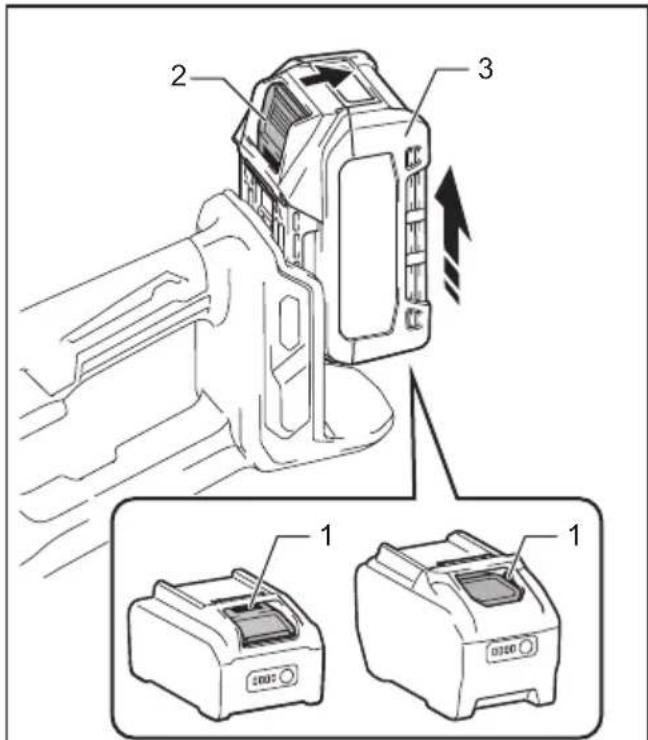
To install the battery cartridge, align the tongue on the battery cartridge with the groove in the housing and slip it into place. Insert it all the way until it locks in place with a little click. If you can see the red indicator as shown in the figure, it is not locked completely.
To remove the battery cartridge, slide it from the tool while sliding the button on the front of the cartridge. ▶ Fig.1: 1. Red indicator 2. Button 3. Battery cartridge
⚠CAUTION: Always install the battery cartridge fully until the red indicator cannot be seen. If not, it may accidentally fall out of the tool, causing injury to you or someone around you.
⚠️CAUTION: Do not install the battery cartridge forcibly. If the cartridge does not slide in easily, it is not being inserted correctly.
Tool / battery protection system
The tool is equipped with a tool/battery protection system. This system automatically cuts off power to the motor to extend tool and battery life. The tool will automatically stop during operation if the tool or battery is placed under one of the following conditions:
Overload protection
When the tool/battery is operated in a manner that causes it to draw an abnormally high current, the tool stops automatically. In this situation, turn the tool off and stop the application that caused the tool to become overloaded. Then turn the tool on to restart.
Overheat protection
When the tool/battery is overheated, the tool stops automatically. In this situation, let the tool/battery cool before turning the tool on again.
Overdischarge protection
When the battery capacity is not enough, the tool stops automatically. In this case, remove the battery from the tool and charge the battery.
Protections against other causes
Protection system is also designed for other causes that could damage the tool and allows the tool to stop automatically. Take all the following steps to clear the causes, when the tool has been brought to a temporary halt or stop in operation.
- Turn the tool off, and then turn it on again to restart.
- Charge the battery(ies) or replace it/them with recharged battery(ies).
- Let the tool and battery(ies) cool down.
If no improvement can be found by restoring protection system, then contact your local Makita Service Center.
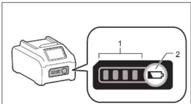
Indicating the remaining battery capacity
Press the check button on the battery cartridge to indicate the remaining battery capacity. The indicator lamps light up for a few seconds.
▶ Fig.2: 1. Indicator lamps 2. Check button
| Indicator lamps Remaining | capacity | ||
| Lighted Off | Blinking | ||
| 75% to 100% | |||
| 50% to 75% | |||
| 25% to 50% | |||
| 0% to 25% | |||
| Charge the battery. | |||
| The battery may have malfunctioned. | |||
NOTE: Depending on the conditions of use and the ambient temperature, the indication may differ slightly from the actual capacity.
NOTE: The first (far left) indicator lamp will blink when the battery protection system works.
Speed adjusting dial
▶ Fig.3: 1. Speed adjusting dial
The strokes per minute can be adjusted just by turning the speed adjusting dial. This can be done even while the tool is running. The dial is marked 1 (lowest speed) to 5 (full speed). Turn the speed adjusting dial between 1 and 5 according to your work.
Refer to the table to select the proper speed for the workpiece to be cut.
| Number on adjusting dial Strokes per minute | |
| 5 2,200 | |
| 4 1,850 | |
| 3 1,500 | |
| 2 1,150 | |
| 1 800 | |
| Workpiece to be cut Number on adjusting dial | |
| Cast iron pipes 5 | |
| Iron pipes 2 - 5 | |
| Stainless steel 1 | |
NOTE: If the tool is operated continuously at low speeds for a long period of time, the operation life of the motor will be reduced.
NOTE: The speed adjusting dial can be turned only as far as 5 and back to 1. Do not force it past 5 or 1, or the speed adjusting function may no longer work.
NOTE: During the cutting of stainless steel pipes, the blade strokes at low speed. If you press the recipro saw blade strongly to the workpiece, the overload protection system may be activated.
NOTE: Generally, faster speeds allow you to cut materials quickly, but the blade gets damaged sooner. Conversely, slower speeds result in slower cutting, but the blade lasts longer. Adjust the blade speed according to your needs.
Switch action
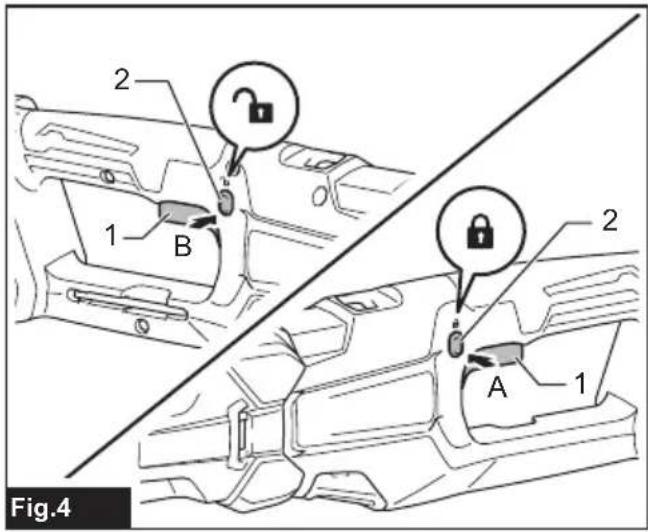
⚠️CAUTION: Before installing the battery cartridge into the tool, always check to see that the switch trigger actuates properly and returns to the "OFF" position when released.
⚠️CAUTION: When not operating the tool, push the trigger-lock button from A side to lock the switch trigger in the OFF position.
▶ Fig.4: 1. Switch trigger 2. Trigger-lock button
To prevent the switch trigger from accidentally pulled, the trigger-lock button is provided.
To start the tool, depress the trigger-lock button from B side and pull the switch trigger. Tool speed is increased by increasing pressure on the switch trigger. Release the switch trigger to stop.
After use, always press in the trigger-lock button from A side.
Electric brake
This tool is equipped with an electric brake. If the tool consistently fails to quickly stop after the switch trigger is released, have the tool serviced at a Makita service center.
Electronic function
The tool is equipped with the electronic functions for easy operation.
Constant speed control
The speed control function provides the constant rotation speed regardless of load conditions.
Soft start feature
Soft start feature reduces starting reaction.
Accidental re-start preventive function
Even if you install the battery cartridge while pulling the switch trigger, the tool does not start.
To start the tool, first release the switch trigger and then pull the switch trigger.
ASSEMBLY
CAUTION: Always be sure that the tool is switched off and the battery cartridge is removed before carrying out any work on the tool.
Hex wrench storage
When not in use, store the hex wrench as shown in the figure to keep it from being lost.
▶ Fig.5: 1. Hex wrench
Installing or removing the recipro saw blade
CAUTION: Always clean out all chips or foreign matter adhering to the blade and around the blade clamp. Failure to do so may cause insufficient tightening of the blade, resulting in a serious injury.
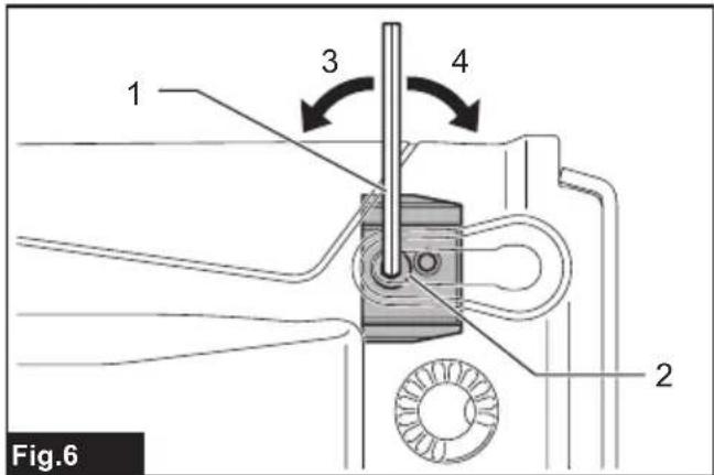
To install the recipro saw blade, first loosen the clamp bolt with a hex wrench.
▶ Fig.6: 1. Hex wrench 2. Clamp bolt 3. Loosen 4. Tighten
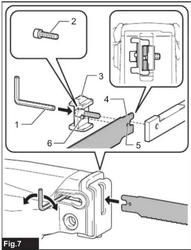
Insert the recipro saw blade straight into the slot of the blade clamp, ensuring projection of the blade clamp fits into the hole of the blade. Then, tighten the clamp bolt with the hex wrench. Finally, pull the blade lightly to ensure that it is securely attached.
▶ Fig.7: 1. Hex wrench 2. Clamp bolt 3. Blade clamp 4. Recipro saw blade 5. Hole 6. Projection
Installing the thin recipro saw blade
Optional accessory
When using the thin recipro saw blade, use the blade clamp S. When installing the blade, insert it straight aligning the slot of the blade clamp.
▶ Fig.8: 1. Thin recipro saw blade 2. Blade clamp S
To remove the recipro saw blade, follow the installation procedure in reverse.
Installing or removing the blade clamp
⚠CAUTION: Always use appropriate blade clamp for the recipro saw blade. Otherwise, the blade may be ejected or folded and cause a personal injury.
You can change the blade clamps according to your work.
NOTE: You can use both sides of the blade clamp.
- To remove the blade clamp, install the battery, lightly pull the switch trigger, and move the clamp bolt to wide-open position. Then remove the battery from the tool.
▶ Fig.9: 1. Switch trigger 2. Clamp bolt
-
Remove the clamp bolt with a hex wrench.
-
Loosen the bolt with a hex wrench and open the shoe.
▶ Fig.10: 1. Hex wrench 2. Bolt 3. Shoe
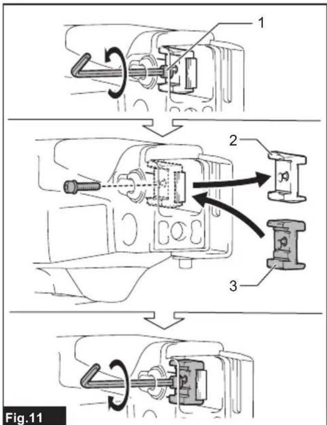
- Remove the blade clamp. Insert the new blade clamp into the gap in the orientation shown in the figure. Then, tighten the clamp bolt to secure the blade clamp.
▶ Fig.11: 1. Clamp bolt 2. Blade clamp 3. Blade clamp S
- Close the shoe and tighten the bolt for the shoe.
Refer to the table below for the correspondence between blade clamps and blades.
| Blade type Blade clamp type | |
| Recipro saw blade for chain vise | Blade clamp |
| Thin recipro saw blade Blade clamp S | |
Installing or removing the front grip
To install the front grip, align the ▲marks on the front grip and the tool as shown in the figure, and mount it onto hole of the tool. Then, insert the grip shaft into the holes and tighten the bolt from the opposite side to secure it.
▶ Fig.12: 1. Front grip 2. ▲ mark 3. Grip shaft 4. Bolt
To remove the front grip, follow the installation procedure in reverse.
NOTICE: Insert the grip shaft into the front grip from the side with the mark.
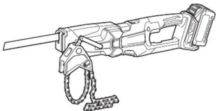
Installing or removing the chain vise
⚠️CAUTION: Do not attach the chain vise on the cut-off side of the workpiece. The tool may fall and cause a personal injury.
- To install the chain vise, place it on the workpiece.
▶ Fig.13: 1. Chain vise 2. Vise pin 3. Cutting position
- Wrap the chain around the workpiece. Then, push the chain into the chain vise hook to secure it.
▶ Fig.14: 1. Chain vise 2. Chain vise hook
- Bend the vise lever and turn it clockwise to tighten the chain.
▶ Fig.15: 1. Vise lever
- Push the tool into the vise pin of the chain vise until it is secured by the ball plunger.
▶ Fig.16: 1. Chain vise 2. Vise pin 3. Ball plunger
NOTE: You can install the chain vise from both of the right and left sides.
- To remove the chain vise, follow the installation procedure in reverse.
OPERATION
CAUTION: Always wear gloves to protect your hands from hot flying chips when cutting metal.
CAUTION: Be sure to always wear suitable eye protection which complies with current national standards.
⚠️ CAUTION: Always use a suitable coolant (cutting oil) when cutting metal. Failure to do so will cause premature blade wear.
CAUTION: Do not quirk the recipro saw blade during cutting. If blade wobbling occurs, adjust the blade speed.
⚠️ CAUTION: When cutting a pipe containing water inside, be careful not to wet the tool. If water enters the tool, it may result in breakdown of the tool or battery cartridge.
⚠️ CAUTION: Do not perform no-load operation with the recipro saw blade installed. It may cause a personal injury.
⚠️ CAUTION: During cutting, do not place your hands or grip any part except the handle.
CAUTION: Keep your hands, face, and other body parts away from the recipro saw blade and the ejected chips.
⚠️ CAUTION: When operating the tool without the chain vise or clamp vise, always press the shoe firmly against the workpiece during operation. If the shoe is removed or held away from the workpiece during operation, strong vibration and/or twisting will be produced, causing the blade to snap dangerously.
CAUTION: When operating the tool without the chain vise or clamp vise, always install the front grip.
CAUTION: When operating the tool without the chain vise or clamp vise, do not allow your hands holding the front grip to touch the cut workpiece at the end of cutting. Touching the workpiece may result in personal injury.
Cutting with chain vise or clamp vise (Optional accessory)
Before starting the operation, fix the vise to the workpiece and install the tool to the vise securely. Bring the recipro saw blade into light contact with the workpiece. Pull the switch trigger lightly to turn the tool on at low speed, and slowly lift the tool to cut the workpiece. Then, increase the speed to continue cutting.
▶ Fig.17: 1. Handle 2. Chain vise
▶ Fig.18: 1. Handle 2. Clamp vise (optional accessory)
| Type of the clamp vise Appropriate material size | |
| Clamp vise 50 10 - 61 mm | |
| Clamp vise 100 73 - 114 mm | |
| Clamp vise 150 140 - 169 mm | |
Cutting without chain vise or clamp vise
Before starting the operation, install the front grip. Press the shoe firmly against the workpiece to stabilize the tool. Bring the recipro saw blade into light contact with the workpiece. First, make a cut at low speed. Then, increase the speed to continue cutting.
▶ Fig.19: 1. Handle
NOTICE: Do not cut the workpiece with the shoe away from the workpiece or without the shoe. Doing so increases the reaction force which may break the recipro saw blade.
MAINTENANCE
⚠️CAUTION: Always be sure that the tool is switched off and the battery cartridge is removed before attempting to perform inspection or maintenance.
NOTICE: Never use gasoline, benzine, thinner, alcohol or the like. Discoloration, deformation or cracks may result.
Cleaning inside of the shoe
You can remove dust and chips from the inside of the tool by opening the shoe.
Loosen the bolt with a hex wrench and open the shoe. Then, remove the dust and chips from the inside of the tool. After cleaning, close the shoe and tighten the bolt firmly with a hex wrench.
▶ Fig.20: 1. Shoe 2. Bolt 3. Hex wrench
Air vent cleaning
The tool and its air vents have to be kept clean. Regularly clean the tool's air vents or whenever the vents start to become obstructed.
▶ Fig.21: 1. Exhaust vent 2. Inhalation vent
Remove the dust cover from inhalation vent and clean it for smooth air circulation.
▶ Fig.22: 1. Dust cover
NOTICE: Clean out the dust cover when it is clogged with dust or foreign matters. Continuing operation with a clogged dust cover may damage the tool.
Maintenance for the chain vise
Regularly lubricate the area of lock bolt on the chain vise as shown in the figure. This will improve the smooth movement of the lock bolt and ensure fastening.
▶ Fig.23: 1. Lock bolt 2. Lubricating area
To maintain product SAFETY and RELIABILITY, repairs, any other maintenance or adjustment should be performed by Makita Authorized or Factory Service Centers, always using Makita replacement parts.
OPTIONAL ACCESSORIES
CAUTION: These accessories or attachments are recommended for use with your Makita tool specified in this manual. The use of any other accessories or attachments might present a risk of injury to persons. Only use accessory or attachment for its stated purpose.
If you need any assistance for more details regarding these accessories, ask your local Makita Service Center.
- Recipro saw blades
• Recipro saw blades (for chain vise) - Blade clamp S
- Clamp vise 50/100/150
• Makita genuine battery and charger
NOTE: Some items in the list may be included in the tool package as standard accessories. They may differ from country to country.
SPÉCIFICATIONS
▶ Fig.22: 1. Pare-poussière
▶ Abb.5: 1. Inbusschlüssel
▶ Abb.20: 1. Schuh 2. Schraube 3. Inbusschlüssel
VEILIGHEIDSWAAR- SCHUWINGEN
▶ Fig.8: 1. Dun reciprozaagblad 2. Zaagbladklem S
▶ Fig.11: 1. Klembout 2. Zaagbladklem 3. Zaagbladklem S
▶ Fig.22: 1. Stofrooster
OPTIONELE ACCESSOIRES
▶ Fig.5: 1. Llave hexagonal