GAWB04HWJW - Workbench Gladiator - Free user manual and instructions
Find the device manual for free GAWB04HWJW Gladiator in PDF.

User questions about GAWB04HWJW Gladiator
0 question about this device. Answer the ones you know or ask your own.
Ask a new question about this device
Download the instructions for your Workbench in PDF format for free! Find your manual GAWB04HWJW - Gladiator and take your electronic device back in hand. On this page are published all the documents necessary for the use of your device. GAWB04HWJW by Gladiator.
USER MANUAL GAWB04HWJW Gladiator
ASSEMBLY INSTRUCTIONS......5
Tools and Parts 5
Workbench Use Requirements......5
Unpack the Workbench ....5
Install Legs and Back Panel....5
Inner Leg Height Adjustment....7
Complete the Assembly......8
Workbench Care 8
Registering Your Product......8
WARRANTY....9
SÉCURITÉ DE L'ÉTABLI....10
DIMENSIONS ......11
PIÈCES ......12
INSTRUCTIONS D'ASSEMBLAGE...13
Your safety and the safety of others are very important.
We have provided many important safety messages in this manual and on your appliance. Always read and obey all safety messages.

This is the safety alert symbol.
This symbol alerts you to potential hazards that can kill or hurt you and others.
All safety messages will follow the safety alert symbol and either the word "DANGER" or "WARNING."
These words mean:
DANGER
You can be killed or seriously injured if you don't immediately follow instructions.
WARNING
You can be killed or seriously injured if you don't follow instructions.
All safety messages will tell you what the potential hazard is, tell you how to reduce the chance of injury, and tell you what can happen if the instructions are not followed.
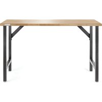
DIMENSIONS
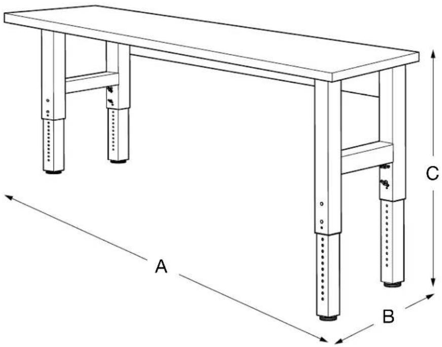
text_image
A B C| Model | GAWB04HWEG GAWB04HWJW | GAWB06HWEG GAWB06HWGW | GAWB08HWEG GAWB08HWGW |
| A | 48"(122 cm) 72"(183 cm) 96"(244 cm) | ||
| B | 25"(63.5 cm) 25"(63.5 cm) 25"(63.5 cm) | ||
| C | 27.5" - 40.8"(69.9 cm - 103.6 cm) | 27.5" - 40.8"(69.9 cm - 103.6 cm) | 27.5" - 40.8"(69.9 cm - 103.6 cm) |
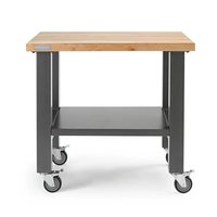
PARTS
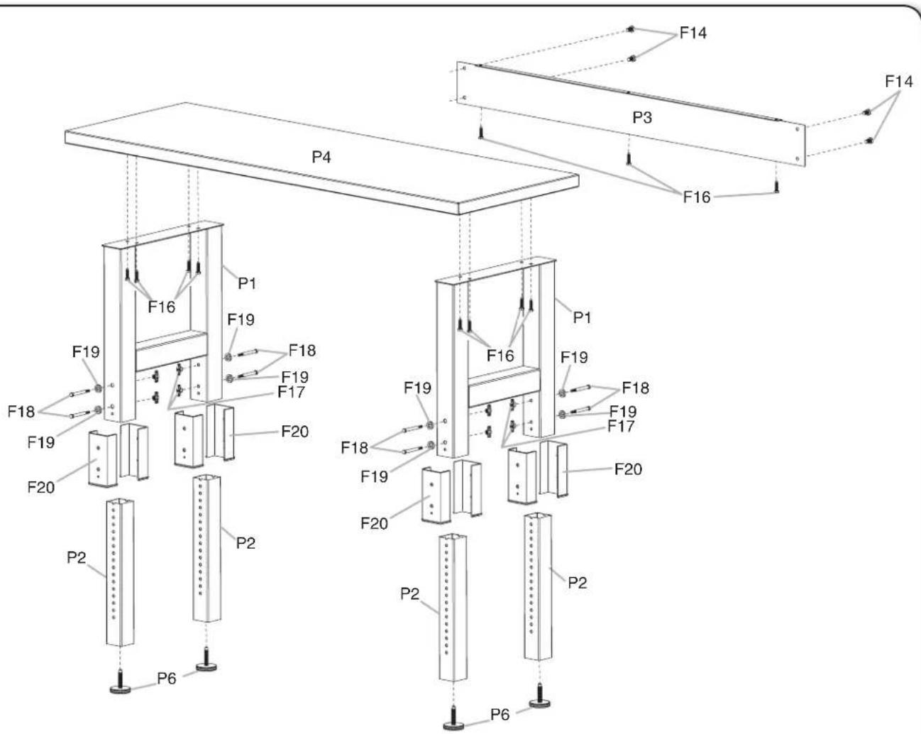
text_image
F14 F14 P3 F16 P4 F16 F19 F18 F19 F17 F18 F19 F20 F20 F16 F19 F18 F19 F17 F20 F18 F19 F20 P2 P2 P6 P6P1. Workbench outer legs
P2. Workbench inner legs
P3. Back panel
P4. Workbench top
P6. 1/2" (12.7 mm) x 2" (50.8 mm) leveling legs
F14. M8 hex-head bolts
F16. 3/8" (9.5 mm) x 1½" (3.81 cm) screws
F17. Wing nuts
F18. 5/16" (8 mm) hex-head bolts
F19. ID 8 mm x OD 12.5 mm x THK 3 mm washer
F20. Bushing
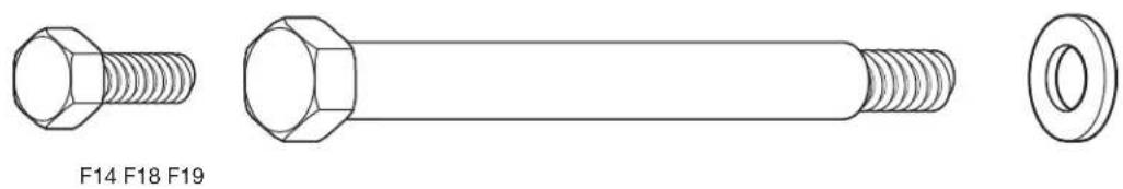
natural_image
Technical line drawings of a hexagonal bolt and its side view (no text or symbols)ASSEMBLY INSTRUCTIONS
Tools and Parts
Gather the required tools and parts before starting installation.
Tools Needed
■ 9/16" socket wrench
■ Adjustable wrench
Parts Supplied
4 ft (121.9 cm), 6 ft (182.9 cm), and 8 ft (243.9 cm) Workbench
■Workbench outer legs (2 welded sets)
■Wingnuts (8)
■Workbench inner legs (4)
■5/16" (8 mm) hex-head bolts (8)
■Workbench back panel
■ID 8 mm x OD 12.5 mm x THK 3 mm washer (8)
■Workbench top
■Bushing (8)
■1/2" (12.7 mm) Leveling legs (4)
■5 mm wrench (1)
■M8 hex-head bolts (5)
■3/8" (9.5 mm) x 1½" (3.81 cm) screws (15)
Workbench Use Requirements
WARNING
Excessive Weight Hazard
Use two or more people to move and assemble workbench.
Failure to do so can result in back or other injury.
■Intended for use in a garage.
■Maximum weight limit is 3,000 lbs (1,360 kg).
■Adding casters to this workbench could be a tipping hazard.
Unpack the Workbench
- Unpack the legs and hardware from the box. Verify contents. See the "Parts Supplied" section.
NOTE: Workbench Legs come fully assembled.
- Remove the back panel and set it aside.
NOTE: Leave the workbench top on the cardboard during assembly.
-
Remove the corners from the workbench top. The bolt holes should be visible. Inspect workbench top prior to assembly.
-
Dispose of/recycle all packaging materials.
Install Legs and Back Panel
NOTE: Assemble and adjust this workbench upside down according to the following illustrations. Be sure that the workbench top is flat on the floor and the legs are in the air. To protect the workbench top during assembly, it is recommended that you place the wood top upside down on the cardboard provided in the package.
- Prepare workbench top
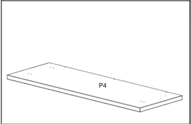
text_image
P4Lay the workbench top (P4) upside down on a clean surface to expose the holes for the leg assembly sets.
- Place leg assemblies
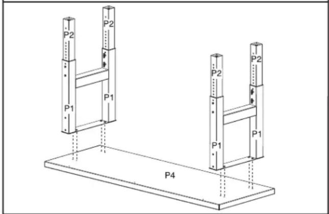
text_image
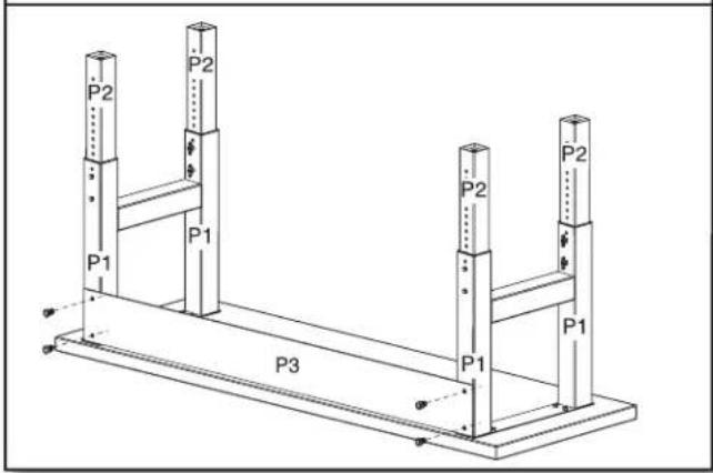
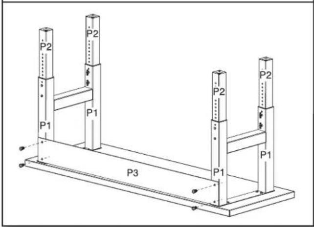
P2 P2 P1 P1 P4 P2 P2 P1 P1Place each outer leg assembly (P1) on the workbench underside. Line up the holes in the outer leg assembly sets with the holes on the bottom of the workbench top (P4). Each outer leg assembly end has two holes that must face the three holes on the back of the wood top for installation of the back panel.
- Attach leg assemblies
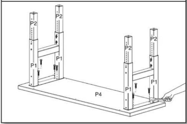
text_image
P2 P2 P1 P1 P4 P2 P2 P1 P1Attach the leg assemblies (P1) to the workbench top (P4) using eight of the provided 3/8" (9.5 mm) x 1 ^1/2 " (3.81 cm) screws (F16). Make sure the screws are inserted straight into the holes. Loosely install the screws using a 9/16" socket wrench. Do not tighten the screws completely.
NOTES:
■Tightening the screws at an angle can place excessive stress on the screws, which may cause the screws to fail.
■The holes in the legs are oval to allow space for minor adjustments as the workbench is assembled.
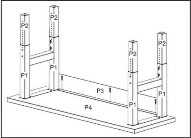
- Attach back panel to workbench top
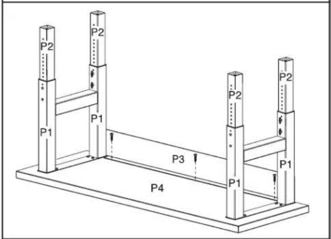
text_image
P2 P2 P1 P1 P3 P2 P2 P1 P4Attach the back panel (P3) to the workbench top (P4) using the remaining screws*. Make sure that the screws are inserted straight into the holes. Tighten the screws using a 9/16" socket wrench.
NOTE: Tightening the screws (F16) at an angle can place excessive stress on the screws, which may cause the screws to fail.
\*NOTE:
For 4' workbench, use two screws (F16). For 6' workbench, use three screws (F16). For 8' workbench, use six screws (F16).
- Attach back panel to leg assemblies
text_image
P2 P2 P1 P1 P3 P2 P2 P1 P1Using a 5 mm wrench, attach the back panel (P3) to the leg assemblies (P1) with the four provided M8 hex-head bolts (F14). Do not tighten the bolts completely.
- Tighten leg assembly bolts
text_image
P2 P1 P1 P3 P1 P2 P2 P2 P1Using a 5 mm wrench, tighten the bolts to attach the back panel (P3) to the outer leg assemblies (P1) completely.
NOTE: Do not overtighten the bolts and screws.
- Tighten bolts and screws
text_image
P2 P2 P1 P1 P3 P2 P2 P1 P4Tighten all remaining bolts and screws. NOTE: Do not overtighten the bolts and screws.
- Attach the leveling legs
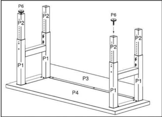
text_image
P6 P2 P2 P6 P1 P1 P2 P2 P3 P4 P1 P1If not already installed, screw in the four leveling legs (P6). The leveling legs have a flat side designed for use with an adjustable wrench, if needed.
IMPORTANT: To install the leveling legs, turn clockwise a minimum of 1½" (3.8 cm), or 12 full turns. Further adjustment can be made 1/4" (6 mm) down from this position or until the leveling leg cannot be turned any further against the bottom of the inner leg (P2).
Inner Leg Height Adjustment
NOTE: Adjust this workbench upside down according to the illustrations. Be sure that the workbench top is flat on the floor and the legs are in the air.
text_image
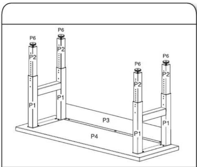
P6 P2 P6 P2 P1 P1 P3 P4 P6 P2 P6 P2 P1Before setting the workbench upright, verify that the same number of adjustment holes are visible with no more than 11 exposed holes on each leg to ensure that the workbench will be level. Align the adjustment holes in the inner leg (P2) with the adjustment holes in the outer leg assembly (P1) at the desired height of the workbench.
- Attach leg assemblies1. Align adjustment ho
text_image
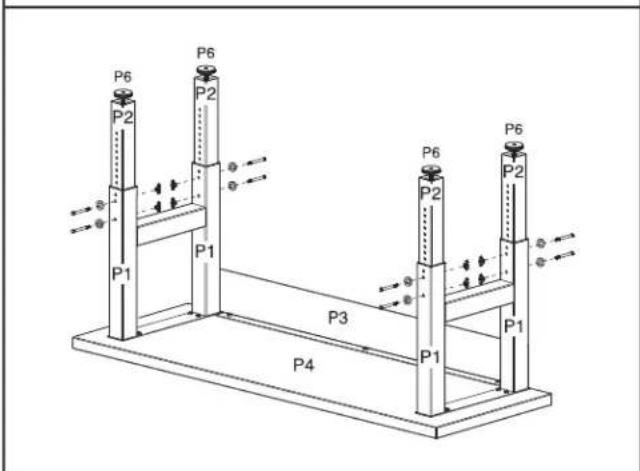
P6 P2 P6 P2 P1 P1 P3 P6 P2 P6 P2 P1 P4Insert a 5/16" (8 mm) hex-head bolt (F18) and washer (F19) and secure with a wingnut (F17). Be sure the hex-head bolt aligns with the hex-shaped adjustment hole. Repeat for each leg.
NOTE: To minimize multiple adjustments during assembly, make sure the adjustment holes are aligned at the same desired height for all the legs.
Complete the Assembly
WARNING
Excessive Weight Hazard
Use two or more people to move and assemble workbench.
Failure to do so can result in back or other injury.
natural_image
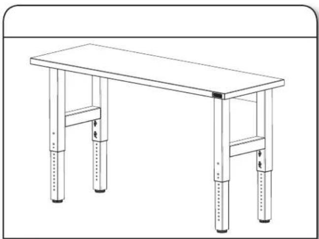
Line drawing of a simple wooden table with four legs and two feet, no text or symbols presentUsing two or more people, stand the workbench upright and place it in its final location.
- Adjust leveling legs1. Stand up workbench
natural_image
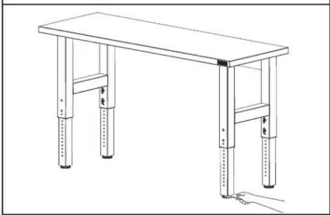
Line drawing of a simple wooden table with four legs and two feet, supported by a hand holding a small object (no text or symbols)Adjust the leveling legs as needed.
IMPORTANT: When adjusting the leveling legs, be sure they are installed at least 1½" (3.8 cm) or 12 full turns deep into the legs.
Workbench Care
- Wash the workbench with a mild detergent and warm water. Do not allow water to remain on the workbench for any length of time.
- Rinse completely and dry thoroughly.
Registering Your Product
There are many benefits of registering your product. Find out more and register your product online at www.gladiatorgarageworks.com. Consumers in Canada can call 1-800-807-6777.
| GLADIATOR® WORKBENCH WARRANTY | ATTACH YOUR RECEIPT HERE. PROOF OF PURCHASE IS REQUIRED TO OBTAIN WARRANTY SERVICE.Please have the following information available when you call the Customer eXperience Center:■Name, address and telephone number■Model number and serial number■A clear, detailed description of the problem■Proof of purchase including dealer or retailer name and address |
IF YOU NEED SERVICE:
- Before contacting us to arrange service, please determine whether your product requires repair. Some questions can be addressed without service. Please take a few minutes to review the instructions or visit www.gladiatorgarageworks.com.
- All warranty service is provided exclusively by our authorized Gladiator Service Providers. In the U.S. and Canada, direct all requests for warranty service to:
Gladiator Customer eXperience Center
In the U.S.A., call 1-866-342-4089. In Canada, call 1-800-807-6777.
If outside the 50 United States or Canada, contact your authorized Gladiator dealer to determine whether another warranty applies.
ONE YEAR LIMITED WARRANTY
WHAT IS COVERED WHAT IS NOT COVERED
ONE YEAR LIMITED WARRANTY ON WOODEN TOP
For one year from the date of purchase, when this product is operated and maintained according to the instructions attached to or furnished with the product, Gladiator will replace or repair the defective product or parts to correct defects in materials or workmanship.
LIFETIME LIMITED WARRANTY ON WORKBENCH METAL SECTIONS
For the life of the product, when the Workbench is used and maintained according to the instructions attached to or furnished with the product, Gladiator will pay for repair or replacement of the defective product or parts to correct defects in materials or workmanship.
- Service calls to correct the installation of any Gladiator products or to instruct you on how to use or install them.
- Damage resulting from improper handling or shipping of products, or products damaged by accident, misuse, abuse, fire, flood, improper installation, acts of God, neglect, corrosion, modification or mishandling.
- Shipping or freight fees to deliver replacement products or to return defective products.
- Repairs or replacement when your product is used in other than normal, single-family household use, such as a commercial environment or handled in any way inconsistent with the installation instructions included with the product.
- Cosmetic damage including scratches, dings, dents or cracks that do not affect the structural or functional capability of the product.
- Replacement parts or product for Gladiator products operated outside the United States and Canada.
- In Canada, travel or transportation expenses for customers who reside in remote areas.
- Any labor costs during the limited warranty period.
- Damage resulting from improper loading beyond the specified maximum weight capacity outlined in the assembly instructions provided with the product.
- Surfaces damaged due to chemical interaction resulting in corrosion of paint or metal.
- Any damage, splitting, checking, cracking or warping of the wooden top past the first year.
The cost of repair or replacement under these excluded circumstances shall be borne by the customer.
DISCLAIMER OF IMPLIED WARRANTIES; LIMITATION OF REMEDIES
IMPLIED WARRANTIES, INCLUDING TO THE EXTENT APPLICABLE WARRANTIES OF MERCHANTABILITY OR FITNESS FOR A PARTICULAR PURPOSE, ARE EXCLUDED TO THE EXTENT LEGALLY PERMISSIBLE. ANY IMPLIED WARRANTIES THAT MAY BE IMPOSED BY LAW ARE LIMITED TO ONE YEAR, OR THE SHORTEST PERIOD ALLOWED BY LAW. SOME STATES AND PROVINCES DO NOT ALLOW LIMITATIONS OR EXCLUSIONS ON HOW LONG AN IMPLIED WARRANTY OF MERCHANTABILITY OR FITNESS LASTS, SO THE ABOVE LIMITATIONS OR EXCLUSIONS MAY NOT APPLY TO YOU. THIS WARRANTY GIVES YOU SPECIFIC LEGAL RIGHTS, AND YOU MAY ALSO HAVE OTHER RIGHTS WHICH VARY FROM STATE TO STATE OR PROVINCE TO PROVINCE.
Outside the 50 United States and Canada, this warranty does not apply. Contact your authorized Gladiator dealer to determine if another warranty applies.
If you need service, call the Gladiator Customer eXperience Center, 1-866-342-4089 (toll-free), from anywhere in the U.S.A. In Canada, contact your Whirlpool Canada LP designated service company or call 1-800-807-6777.
In the United States, Gladiator means Whirlpool Corporation, Benton Harbor, Michigan 49022. In Canada, Gladiator means Whirlpool Canada LP, Mississauga, ON L5N 3A7.
Keep this book and your sales slip together for future reference. You must provide proof of purchase or installation date for in-warranty service.
Write down the following information about your Workbench to better help you obtain assistance or service if you ever need it. You will need to know your complete model number and serial number. You can find this information on the model and serial label located on the back of the product.
Dealer name
Address
Phone number
Model number
Serial number
Purchase date
SÉCURITÉ DE L'ÉTABLI
natural_image
Line drawing of a simple wooden table with four legs and four feet, no text or symbols presentnatural_image
Line drawing of a simple wooden table with four legs and two supports, no text or symbols presentnatural_image
Line drawing of a hexagonal bolt with threaded shaft (no text or symbols)