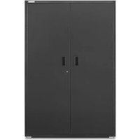
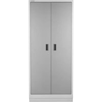
GAGD277DKR - Tool cabinet Gladiator - Free user manual and instructions
Find the device manual for free GAGD277DKR Gladiator in PDF.

User questions about GAGD277DKR Gladiator
0 question about this device. Answer the ones you know or ask your own.
Ask a new question about this device
Download the instructions for your Tool cabinet in PDF format for free! Find your manual GAGD277DKR - Gladiator and take your electronic device back in hand. On this page are published all the documents necessary for the use of your device. GAGD277DKR by Gladiator.
USER MANUAL GAGD277DKR Gladiator
Assembly Instructions
ARMOIRE À OUTILS
MODULAIRE ET
ASSEMBLY INSTRUCTIONS......3
Tools and Parts 3
Cabinet Use Requirements......3
Unpack the Cabinet......3
Install the Bumpers....3
Install the Casters 4
WARRANTY....5
SÉCURITÉ DE L'ARMOIRE ......6
PIÈCES....6
INSTRUCTIONS D'ASSEMBLAGE.....7
Your safety and the safety of others are very important.
We have provided many important safety messages in this manual and on your appliance. Always read and obey all safety messages.

This is the safety alert symbol.
This symbol alerts you to potential hazards that can kill or hurt you and others.
All safety messages will follow the safety alert symbol and either the word "DANGER" or "WARNING."
These words mean:
DANGER
You can be killed or seriously injured if you don't immediately follow instructions.
WARNING
You can be killed or seriously injured if you don't follow instructions.
All safety messages will tell you what the potential hazard is, tell you how to reduce the chance of injury, and tell you what can happen if the instructions are not followed.
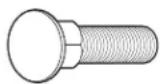
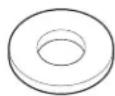
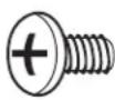
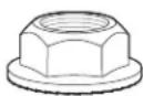
PARTS
F1
F2 F3
F4
| Label Description Quantity | |
| F1 M6 x 14 mm Carriage bolts 16 | |
| F2 M6 Shoulder washer 8 | |
| F3 M6 x 12 mm Phillips-head screw 8 | |
| F4 M6 Self-locking nuts 16 |
ASSEMBLY INSTRUCTIONS
Tools and Parts
Gather the required tools and parts before starting installation.
Tools Needed:
■ 10 mm wrench
■ Phillips screwdriver
■Flat-blade screwdriver
Parts Supplied:
■ Key (2)
■ M6 Shoulder washers (8)
■ Top mat (1)
■ Rigid casters (2)
■ Drawer model: Drawer liners (5) Cabinet model: Tray liner (1)
■Swivel casters (2)
■ L-shaped bumpers (2)
■ M6 Self-locking nuts (16)
■M6 x 12 mm Phillips-head screws (8)
■M6 x 14 mm Carriage-head bolts (16)
Cabinet Use Requirements
■Intended for use in a garage.
■Maximum weight limit is 65 lbs (29 kg) per drawer/shelf.
■Maximum weight limit is 1,400 lbs (635 kg) per cabinet.
Unpack the Cabinet
NOTE: Keep the packing materials to cushion the cabinet during assembly and then dispose of/recycle all packaging materials.
- Open the doors or drawers.
- Verify contents. See "Parts Supplied."
Install the Bumpers
WARNING
Excessive Weight Hazard
Use two or more people to move, assemble or install cabinet.
Failure to do so can result in back or other injury.
Close and lock the doors or drawers. Remove the key.
NOTE: The drawers must be pushed in completely to lock. Remove the top mat from the cabinet. Using two or more people, turn the cabinet upside down.
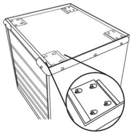
- Install the bumpers
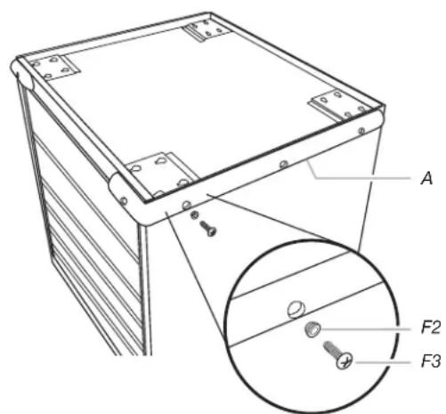
text_image
A F2 F3A. Bumper F2. Shoulder washer
F3. Phillips-head screw
Attach the bumpers to the front corners using four shoulder washers (F2) and four Phillips-head screws (F3) for each bumper.
NOTE: To keep from stripping the screws, do not overtighten. Using a Phillips screwdriver, tighten all the screws.
Install the Casters
2a. Install the casters
natural_image
Technical line drawing of a mechanical housing or enclosure with mounting brackets and a magnified inset showing internal components (no text or symbols)Insert the carriage-head bolts (F1) into the keyhole slots and slide the bolts into place as shown. Position the two rigid casters over the bolts in the front cabinet location, with the brakes toward the inside, and start four self-locking nuts for each caster. Hold the casters in place, making sure the bolts are seated in the narrow ends of the keyhole slots. Tighten the self-locking nuts (F4) with a 10 mm wrench. To attach the two swivel casters to the rear caster location, repeat previous steps.
2b. Install the casters
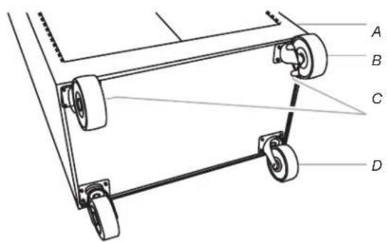
text_image
A B C DA. Front of cabinet
C. Caster brakes
B. Rigid casters
D. Swivel casters
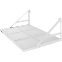
- Install the Convertible Tray or Drawers
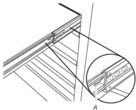
natural_image
Technical line drawing of a wooden deck structure with an inset showing a bracket detail (no text or symbols)A. Lever
Removing the Convertible Tray or Drawer:
Unload the contents from the convertible tray or drawer. Slide out the convertible tray or drawer as far as it will go. Press the lever down on the right-hand track and lift the lever up on the left track to release the convertible tray or drawer.
Replacing the Convertible Tray or Drawer:
Align the convertible tray or drawer guides with the receiving glides. Hold the receiving glides firmly and insert the convertible tray or drawer guide.
NOTE: It is normal for the convertible tray or drawer to close tightly the first time after it has been removed.
Push the convertible tray or drawer in completely.
Return the cabinet to its upright position. Replace the top mat with the textured side facing up. Unlock the doors or drawers. Place the liner(s) in the tray or the drawers.
WARRANTY
For warranty information:
In the U.S.A. call 1-866-342-4089 or visit our website at
www.GladiatorGW.com
In Canada call 1-800-807-6777 or visit our website at
www.gladiatorgarageworks.ca
SÉCURITÉ DE L'ARMOIRE
natural_image
Technical line drawing of a rectangular electronic device with mounting holes and a magnified inset showing internal components (no text or symbols)natural_image
Technical line drawing of a wooden shelf assembly with an inset showing a bracket detail (no text or symbols)A. Levier
www.gladiatorgarageworks.ca
natural_image
Technical line drawing of a mechanical housing or enclosure with mounting brackets and a magnified inset showing internal components (no text or symbols)natural_image
Technical line drawing of a wooden shelf assembly with an inset showing a close-up detail (no text or symbols)A. Palanca
www.gladiatorgarageworks.ca