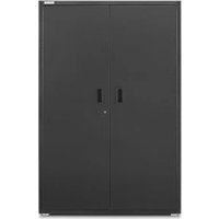
GAWA30SFRG - Tool cabinet Gladiator - Free user manual and instructions
Find the device manual for free GAWA30SFRG Gladiator in PDF.



| Product type | Wall-mounted tool cabinet |
| Brand | Gladiator |
| Model | GAWA30SFRG |
| Width | 76.2 cm (30 inches) |
| Height | 76.2 cm (30 inches) |
| Depth | Approximately 35.6 cm (14 inches) |
| Maximum load capacity per shelf | 22 kg (50 lb) |
| Maximum load capacity of cabinet | 91 kg (200 lb) |
| Number of shelves included | 2 |
| Material | Steel |
| Power supply | None (manual storage) |
| Main functions | Tool storage, adjustable shelves, wall mounting |
| Maintenance and cleaning | Clean with a soft cloth and mild detergent |
| Safety | Use two people for installation; respect maximum loads |
| Parts included | Mounting brackets (2), M8x16 mm bolts (4), M12 washers (4), M8 nuts (4), wrench (2) |
| Wall compatibility | GearWall panels, GearTrack profiles, or standard wall |
| Warranty | Consult the manual or contact customer service |
Frequently Asked Questions - GAWA30SFRG Gladiator
User questions about GAWA30SFRG Gladiator
0 question about this device. Answer the ones you know or ask your own.
Ask a new question about this device
Download the instructions for your Tool cabinet in PDF format for free! Find your manual GAWA30SFRG - Gladiator and take your electronic device back in hand. On this page are published all the documents necessary for the use of your device. GAWA30SFRG by Gladiator.
USER MANUAL GAWA30SFRG Gladiator
GAWG241DRG - 24" Hammered Granite/Silver Tread
GAWG241DDR - 24" Hammered Granite/Red Tread
GAWG241DKW - 24" Hammered White/Gray Slate
GAWG302DRG - 30" Hammered Granite/Silver Tread
GAWG302DDR - 30" Hammered Granite/Red Tread
GAWG302DZW - 30" Hammered White/Gray Slate
GAWA30SFRG - 30" Hammered Granite
GAWA30SFZW - 30" Hammered White
GAWA48SFRG - 48" Hammered Granite
GAWA48SFZW - 48" Hammered White
Modèles
GAWG241DRG - 24" Ardoise Martelée/Texturé argenté
GAWG241DDR - 24" Ardoise martelée/Texturé rouge
GAWG241DKW - 24" Blanc martelé/ardoise grise
GAWG302DRG - 30" Ardoise Martelée/Texturé argenté
GAWG302DDR - 30" Ardoise martelée/Texturé rouge
GAWG302DZW - 30" Blanc martelé/ardoise grise
GAWA30SFRG - 30" Ardoise Martelée
GAWA30SFZW - 30" Blanc Martelé
GAWA48SFRG - 48" Ardoise Martelée
GAWA48SFZW - 48" Blanc Martelé
Modelos
GAWG241DRG - 24" Granito Martillado/Plateado Huella
GAWG241DDR - 24" Granito Martillado/Rojo huella
GAWG241DKW - 24" Blanco forjado/Teja gris
GAWG302DRG - 30" Granito Martillado/Plateado Huella
GAWG302DDR - 30" Granito Martillado/Rojo huella
GAWG302DZW - 30" Blanco forjado/Teja gris
GAWA30SFRG - 30" Granito Martillado
GAWA30SFZW - 30" Blanco Martillado
GAWA48SFRG - 48" Granito Martillado
GAWA48SFZW - 48" Blanco Martillado
24" (60.96 CM) AND 30" (76.20 CM) PREMIER WELDED-STEEL WALL GEARBOX CABINET
Assembly Instructions
ARMOIRE MURALES À OUTILS EN ACIER SOUDÉ DE HAUTE QUALITÉ, 24 PO (60,96 CM) ET 30 PO (76,20 CM)
CABINET SAFETY......2
PARTS....2
ASSEMBLY INSTRUCTIONS......3
Tools and Parts ....3
Cabinet Use Requirements......3
Unpack the Cabinet....3
Install the Cabinet to the Wall......3
Adjust Shelves ....5
Adjust Door(s) 6
Reverse Door (24" [60.96 cm] Wall
Cabinet Only) 6
WARRANTY....6
SÉCURITÉ DE L'ARMOIRE .....7
PIÈCES 7
INSTRUCTIONS D'ASSEMBLAGE.....8
Your safety and the safety of others are very important.
We have provided many important safety messages in this manual and on your appliance. Always read and obey all safety messages.

This is the safety alert symbol.
This symbol alerts you to potential hazards that can kill or hurt you and others.
All safety messages will follow the safety alert symbol and either the word "DANGER" or "WARNING."
These words mean:
DANGER
You can be killed or seriously injured if you don't immediately follow instructions.
WARNING
You can be killed or seriously injured if you don't follow instructions.
All safety messages will tell you what the potential hazard is, tell you how to reduce the chance of injury, and tell you what can happen if the instructions are not followed.
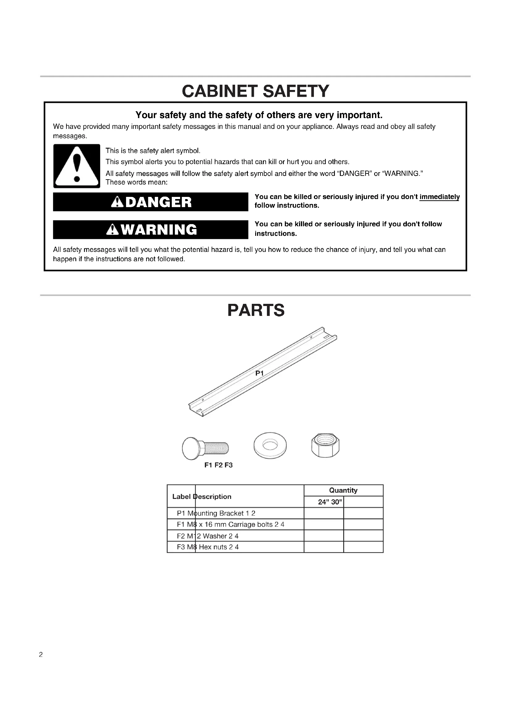
PARTS


F1 F2 F3

| Label Description | Quantity | |
| 24" 30" | ||
| P1 Mounting Bracket 1 2 | ||
| F1 M8 x 16 mm Carriage bolts 2 4 | ||
| F2 M1 2 Washer 2 4 | ||
| F3 M8 Hex nuts 2 4 | ||
ASSEMBLY INSTRUCTIONS
Tools and Parts
Gather the required tools and parts before starting installation.
Tools Needed:
■13 mm Wrench (GearWall® panel or GearTrack® channel mount)
■7/16" Wrench (Standard mount)
■ Phillips-head screwdriver
■ Blunt Tool
Parts Needed for Standard Mount:
■ 1/2" - 20 x 1½" Lag screws (4)
■ 1/4" Flat washers (4)
Parts Supplied for 24" (60.96 cm) Cabinet:
■ Full-width shelf (1)
■ M8 Hex nuts (2)
■M8 x 16 mm Carriage bolts (2)
■M12 Washer (2)
■Mounting bracket (1)
Parts Supplied for 30" (76.20 cm) Cabinet:
■ Full-width shelves (2)
■ M8 Hex nuts (4)
■M8 x 16 mm Carriage bolts (4)
■M12 Washer (4)
■ Mounting brackets (2)
■ Key (2)
Cabinet Use Requirements
■Intended for use in a garage, storage area, laundry room, etc.
■Maximum weight limit is 50 lbs (22 kg) for each shelf.
■ Maximum weight limit is 150 lbs (68 kg) for the 24" (60.96 cm) cabinet.
■ Maximum weight limit is 200 lbs (91 kg) for the 30" (76.20 cm) cabinet.
Unpack the Cabinet
- Open the cabinet door.
- Remove and verify the contents. See "Parts Supplied" in "Tools and Parts."
- Dispose of/recycle all packaging materials.
Install the Cabinet to the Wall
WARNING
Excessive Weight Hazard
Use two or more people to move, assemble or install cabinet.
Failure to do so can result in back or other injury.
IMPORTANT: Decide if you are going to mount the cabinet on Gladiator® GearWall® panels or GearTrack® channels, or on a standard wall. Follow the instructions that apply to your installation.
1. Install cabinet to GearWall ® panels or GearTrack ® channels

IMPORTANT: Be sure the Gladiator® GearWall® panels or GearTrack® channels are installed with mounting screws in every slot and at every stud location with a maximum of 24" (60.96 cm) horizontally between screws. If Gladiator® GearTrack® channels will be used to mount the Welded-Steel Wall GearBox cabinet, they must be installed 18" (45.72 cm) apart.
24" (60.96 cm) Cabinet
- Attach bracket


F1

F2

F3
With the rims of a mounting bracket pointing down, align the holes in the bracket with the pair of holes in the back panel. Working from the back, insert a carriage bolt (F1) through the bracket and back panel as shown. Working from the cabinet interior, fasten each bolt with a washer (F2) and a hex nut (F3). Completely tighten the nuts.
- Install cabinet
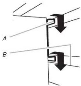
A. Bracket rim C. Mounting bracket fully engaged B. Slot

IMPORTANT: If installing cabinet on GearTrack® channel, a second channel should be installed 18" (45.72 cm) below the bottom of the supporting channel so the cabinet will hang level. Close the cabinet door. Determine cabinet mounting location on a GearWall® panel or GearTrack® channels. Using two or more people, engage the mounting bracket into the wall slots by lifting up, pushing toward the wall and lowering the bracket rims into the slots as shown. Make sure the mounting bracket is fully engaged in the slots as shown. If you want to reverse the door, see "Reverse Door."
30" (76.20 cm) Cabinet
- Attach bracket


F1

F2

F3
With the rims of a mounting bracket pointing down, align the holes in the bracket with the pair of holes in the back panel. Working from the back, insert a carriage bolt (F1) through the bracket and back panel. Working from the cabinet interior, fasten each bolt with a washer (F2) and a hex nut (F3). Completely tighten the nuts. With the rims of the mounting bracket pointing down, align the holes in the bracket with the pair of slots in the back panel. Working from the back, insert a carriage bolt (F1) through the lower bracket and back panel. Working from the cabinet interior, fasten each bolt with a washer (F2) and a hex nut (F3). Only hand tighten the nuts. The lower bracket will need to be adjusted to mount the cabinet on the wall.
IMPORTANT: Completely tighten the hex nuts (F3) on the lower bracket after mounting the cabinet on the wall.
- Install cabinet

A. Bracket rim C. Mounting bracket fully engaged B. Slot
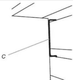
Close the cabinet doors. Determine cabinet mounting location on GearWall® panel or GearTrack® channels. Using two or more people, engage the top mounting bracket into the wall slots by lifting up, pushing toward the wall and lowering the bracket rims into the slots as shown. Make sure the top mounting bracket is fully engaged in the slots as shown. Open the cabinet doors. From the cabinet interior, lift up on the two lower bolts to adjust the lower mounting bracket so that it aligns with the slots on the GearWall® panel or GearTrack® channels. Push the cabinet toward the GearWall® panel or GearTrack® channels and lower the lower bracket rims into the slots. Make sure the bottom mounting bracket is fully engaged in the slots. Using a 13 mm wrench, tighten the two nuts on the bottom wall mounting bracket.
- Inspect the cabinet from the sides

Inspect the cabinet from the sides to ensure both the top and bottom wall-mounting brackets are fully engaged in their respective slots as shown.
- Install cabinet to a standard wall

A. Holes for standard wall mounting
IMPORTANT: The round holes in the top and bottom cabinet back panels are spaced 8" (20.32 cm) apart to allow you to mount the wall cabinet to your garage wall studs. Locate the wood studs in your garage wall. Align two holes at the top and two holes at the bottom with the wood studs, and mark the location of the holes. While two or more people hold the cabinet against the wall, attach the wall cabinet to the garage wall using 1/4" flat washers and 1/4" - 20 x 1½" Lag screws (not provided). Using a 7/16" wrench, fully tighten the screws.
Adjust Shelves
- Remove the shelves

A. Push down
B. Lift up

A. Remove the shelf
Remove the shelf clips from their shipping position on the sides and rear of the cabinet. Working from the inside of the cabinet and using a blunt tool, push out the plastic shelf clips. Discard the clips. Lift up on the underside of the shelf until the shelf tabs are free of the cabinet slots. Tilt the shelf up to reposition it within the cabinet or to remove it from the cabinet.
- Replace the shelves

A. Insert the shelf
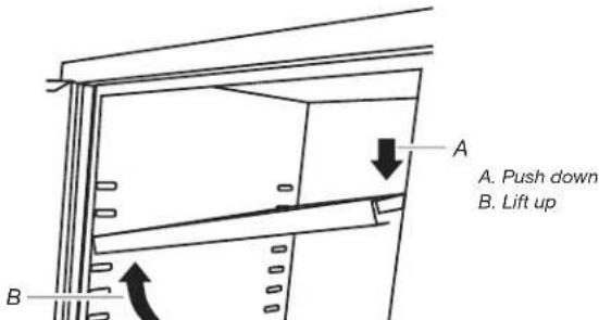

A. Slot B. Shelf tab
NOTE: Plan your shelf heights and install shelves starting from the bottom. The shelves are supported by the metal tabs on the back and side walls of the cabinet. Determine the placement of the shelves. Tilt the shelf so that one end is higher than the other as shown. Insert the shelf into the cabinet so that the higher end is directly above the desired slots and push the shelf down in place behind the side slots. Raise the lower end so it is directly above the desired slots and push the shelf down.
NOTE: Make sure the shelf tabs are in place behind all the slots, as shown. Repeat this process for the other shelf.
Adjust Door(s)
The cabinets are designed with adjustable door(s).
- Using a Phillips-head screwdriver, loosen all screws attaching the hinge to the cabinet.
- Adjust door to the desired height.
- Tighten the screws.
Reverse Door (24" [60.96 cm] Wall Cabinet Only)
- Using a Phillips-head screwdriver, remove all the screws attaching the door hinge to the cabinet.
- Using the screws removed in Step 1, reattach the door hinge to the opposite side of the cabinet.
WARRANTY
For warranty information:
In the U.S.A. call 1-866-342-4089 or visit our website at
www.gladiatorgarageworks.com
In Canada call 1-800-807-6777 or visit our website at
www.gladiatorgarageworks.ca
SÉCURITÉ DE L'ARMOIRE
F1 F2 F3
www.gladiatorgarageworks.com
www.gladiatorgarageworks.ca
F1 F2 F3
A. Saque el estante
www.gladiatorgarageworks.com
www.gladiatorgarageworks.ca


- MODÈLES
- MODELOS
- YOUR SAFETY AND THE SAFETY OF OTHERS ARE VERY IMPORTANT
- DANGER
- WARNING
- ASSEMBLY INSTRUCTIONS
- TOOLS AND PARTS
- TOOLS NEEDED
- PARTS NEEDED FOR STANDARD MOUNT
- PARTS SUPPLIED FOR 24" (60.96 CM) CABINET
- PARTS SUPPLIED FOR 30" (76.20 CM) CABINET
- CABINET USE REQUIREMENTS
- UNPACK THE CABINET
- INSTALL THE CABINET TO THE WALL
- INSTALL CABINET TO GEARWALL ® PANELS OR GEARTRACK ® CHANNELS
- 24" (60.96 CM) CABINET
- 30" (76.20 CM) CABINET
- ADJUST SHELVES
- ADJUST DOOR(S)
- REVERSE DOOR (24" [60.96 CM] WALL CABINET ONLY)
- WARRANTY
- SÉCURITÉ DE L'ARMOIRE
Brand : Gladiator
Model : GAWA30SFRG
Category : Tool cabinet