7163 - Motion detector Heath Zenith - Free user manual and instructions
Find the device manual for free 7163 Heath Zenith in PDF.

User questions about 7163 Heath Zenith
0 question about this device. Answer the ones you know or ask your own.
Ask a new question about this device
Download the instructions for your Motion detector in PDF format for free! Find your manual 7163 - Heath Zenith and take your electronic device back in hand. On this page are published all the documents necessary for the use of your device. 7163 by Heath Zenith.
USER MANUAL 7163 Heath Zenith
Dated receipt required for warranty replacement.
FEATURES
- Solar Powered LED
• Power Reserve Technology
• Wall or Eave Mount
• Cord Management System
• Night Operation Only
UNPACKING
Be sure to remove all contents from packaging and verify all items are present before assembling this light fixture. This package includes the following items:
• Security Light • Solar Panel
- Mounting Hardware • Owner's Manual
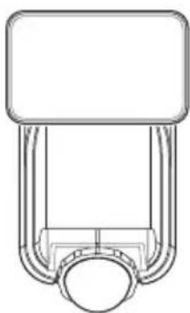
natural_image
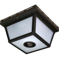
Pure mechanical component diagram without any text, numbers, or symbols7162
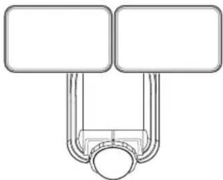
natural_image
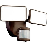
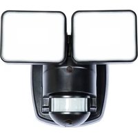
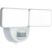
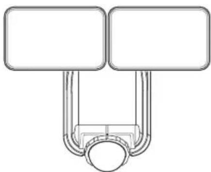
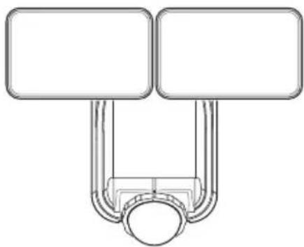
Pure diagram of two vertical rectangles connected to a central circular object (no text or symbols)7163/7164
Note: All illustrations show model 7163. The instructions are the same for all models.
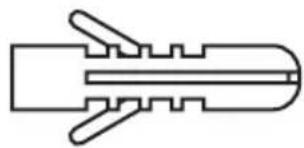
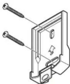
HARDWARE INCLUDED

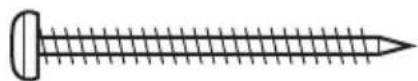
Mounting Screw (x4) Wall Anchor (x4)
natural_image
Pure line drawing of a mechanical component without any text, numbers, or symbolsDESCRIPTION
This light operates from a built-in lithium-ion battery charged from a solar panel. It will also hold three "C" alkaline batteries (not included) which are used as a backup power source. If the solar battery becomes depleted, the light will automatically switch to the alkaline batteries. When the solar panel has recharged the solar battery, the light will automatically switch back to the solar battery.
INITIAL BATTERY CHARGE
IMPORTANT: The solar panel requires full, direct sunlight to charge the battery. Clouds, rain, snow, and other weather conditions may not allow the solar panel to completely recharge the battery. Other obstructions such as buildings or trees may block the sun as well.
When installing the solar panel, make sure it is aimed as described below with a minimum amount of obstructions. If possible, mount the panel facing toward the southern sky.
- PRIOR TO USE, the solar panel will need to be connected to the battery (see Installation instructions) and the battery will require 3 to 7 days of full sun to completely charge with the control dial in the OFF position. Remove the rubber plug from the bottom of the light fixture and insert the end of the solar panel cable into the opening. If possible, aim the solar panel toward the south and tilt it approximately 50^ from horizontal. If the solar panel cannot be aimed toward the south, then tilt the panel approximately 30^ if possible.
- Actual operating time will vary depending upon how frequently the light is turned on by the motion sensor.
- Solar lighting is not designed to equal standard 120V lighting. The amount of light output is reduced to allow the sun time to fully recharge the battery between lighting cycles.
- Solar collection is only effective in direct sunlight. Every hour the light is on requires a minimum of 16 hours of sunlight charging. Solar panels collect less than 10% of the sun's energy.
MOUNTING LOCATION
The most important thing to remember for the operation of your solar powered motion sensing light is that it works from the power received from direct sunlight. The more direct sunlight the solar panel receives in a day, the longer the light will operate.
Solar Light Fixture
The main unit contains the LEDs, motion sensor, and battery. When deciding where to mount this unit, keep in mind that the motion sensor that activates the light has a “field of vision” of 40 feet (12 meters) in front of the light and about 180^ detection angle at a surrounding air temperature of 77^ F ( 25^ C).
Solar Panel
The solar panel converts the sun's energy into electricity, thus charging the battery stored in the solar light fixture. The solar panel requires direct sunlight falling onto the face of the solar panel for as long as possible over the course of the day.
When choosing the location for the solar panel, make sure it is aimed toward the south and is tilted to a suitable angle to allow as much direct sunlight to fall upon it as possible. Make sure there is a minimum amount of obstructions between the solar panel and the sun.
Also, make sure your solar panel location is not too far away from the solar light fixture for the wires to reach and connect.
IMPORTANT SAFETY AND INSTALLATION INFORMATION
Before installing security light, read all instructions carefully and keep owner's manual for future reference.
- WARNING: To prevent possible SERIOUS INJURY or DEATH never allow small children near batteries. If battery is swallowed, immediately notify a doctor.
- WARNING: DO NOT mix old and new batteries. DO NOT mix battery types - such as alkaline, heavy duty, and rechargeable - in a single device. Battery leakage may occur.
- WARNING: DO NOT DISPOSE OF BATTERIES IN FIRE. BATTERIES MAY EXPLODE OR LEAK.
- CAUTION: Burn hazard. Allow the light fixture to cool before touching.
- NOTICE: When replacing batteries, recycle used batteries or dispose of them in accordance with local regulations.
- This fixture is designed for outdoor installation and should be mounted to a wall or eaves.
- To achieve best results, this fixture should be mounted 8 feet (2.4 meters) above the ground.
- Do not cut the solar panel wire. Discontinue use if the wire becomes frayed or broken.
- Do not immerse components in liquid.
- Do not use any other charging device other than the single solar charging panel provided with this light. Doing so may result in injury or damage to the light and voids any warranty.
- Position the cord so that it is securely fastened and will not result in a hazard (such as tripping).
This device complies with Part 15 of the FCC Rules. Operation is subject to the following two conditions: (1) this device may not cause harmful interference, and (2) this device must accept any interference received, including interference that may cause undesired operation.
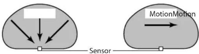
The motion sensor on this light fixture detects “motion” by the movement of heat across the coverage area. The motion sensor is more sensitive to the movement of heat moving across the coverage area and less sensitive to the movement of heat directly towards it.
flowchart
graph TD
    A["Input"] --> B["Sensor"]
    C["Input"] --> D["Sensor"]
    E["MotionMotion"] --> F["Output"]
Least Sensitive Most Sensitive
natural_image
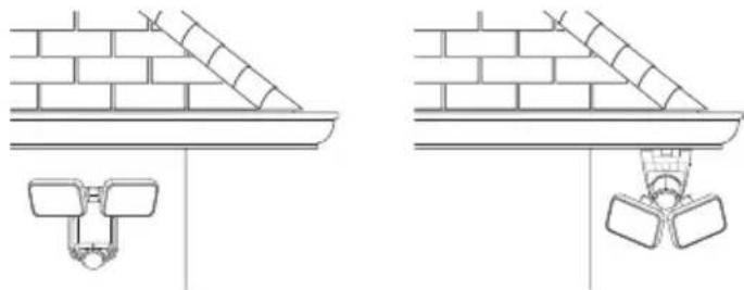
Technical line drawing showing two views of a brick wall fixture with a mounted bracket (no text or symbols)Wall Mount Eave Mount
Note: Light fixture and sensor should be mounted as shown above when installed (depending upon type of installation).
INSTALLATION
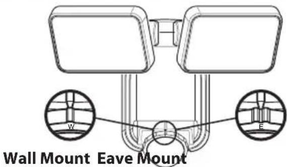
Setting the Sensor for Wall or Eave Mounting
- For wall mounting, turn the ring around the sensor clockwise until the "W" and the single indicator is aligned with the mark on the front of the sensor (see Figure 1).
- For eave mounting, turn the ring around the sensor counterclockwise until the "E" and the double indicator is aligned with the mark on the front of the sensor. (see Figure 1).
Note: There is a detent at each setting to indicate proper alignment of the sensor.
Mounting the Solar Light Fixture
This fixture comes with a mounting plate. It is pre-assembled on the light fixture for shipping.
Make sure there is enough vertical space above the mounting plate to allow the light fixture to be mounted.
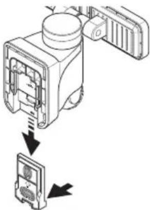
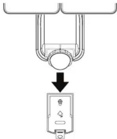
- Press the bottom tab of the wall mounting plate and slide the mounting plate from the light body (see Figure 2).
-
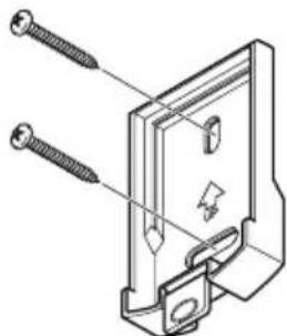
Place the mounting plate against the mounting surface and ensure the mounting plate is level. Mark the hole locations (see Figure 3).
-
If mounting to a wooden surface, drill two 3/32 in. holes into the mounting surface. Install the two mounting screws through the mounting plate and into the mounting surface.
- If mounting to wall board or brick, drill two 7/32 in. holes into the mounting surface. Insert the wall anchors and attach the mounting plate using the two mounting screws.
text_image
Wall Mount Eave MountFigure 1
natural_image
Diagram of a device with internal components and directional arrows indicating assembly or operation (no text or symbols present)Figure 2
natural_image
Technical line drawing of a mechanical component with screws and mounting holes (no text or symbols)Figure 3
-
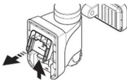
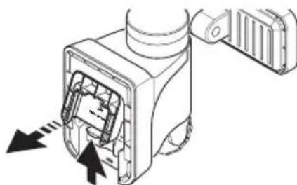
Press up on the battery compartment cover locking tab and swing the cover out and down to remove (see Figure 4).
-
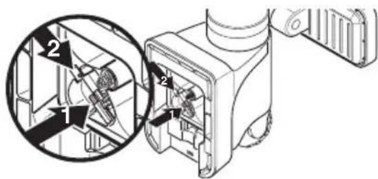
This light fixture is shipped with the internal, rechargeable, Li-ion battery disconnected from the light.
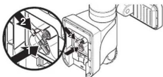
- Gently press down on the wiring harness as shown by arrow 1 (see Figure 5). - Slide the mail connector into the female connector as shown in arrow 2 (see Figure 5).
IMPORTANT: Once the the solar battery harness is connected, there will be no need to touch this harness again.
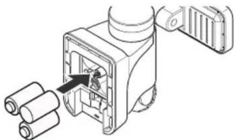
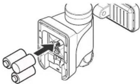
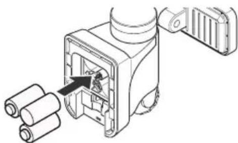
- Install three, 1.5V "C" batteries (not included) into the battery compartment (see Figure 6). Make sure the polarity of the batteries is correct. Replace the battery compartment cover.
IMPORTANT: The "C" batteries are used when the rechargeable solar battery is depleted. When the "C" batteries are depleted, a red LED will flash inside the motion sensor and the "C" batteries will need to be replaced.
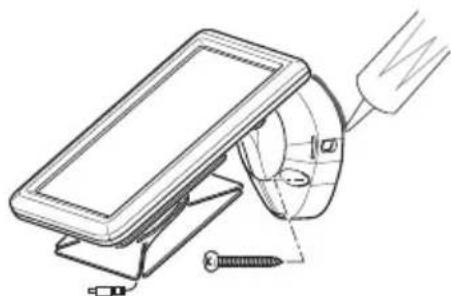
- Slide the rear of the light fixture down onto the mounting plate until it snaps into place (see Figure 7).
Mounting the Solar Panel
- Place the solar panel against the mounting surface and mark the mounting holes (see Figure 8).
- If mounting to a wooden surface, drill two 3/32 in. holes into the mounting surface. Install the two mounting screws through the base and into the mounting surface. - If mounting to wall board or brick, drill two 7/32 in. holes into the mounting surface. Insert the wall anchors and attach the base using the two mounting screws.
IMPORTANT: Caulk around the base and on top of the screw heads after installation.
natural_image
Technical line drawing of a mechanical assembly with screw and nut components (no text or symbols)Figure 8
natural_image
Technical line drawing of a mechanical device with internal components and directional arrows (no text or symbols)Figure 4
text_image
Technical diagram showing mechanical assembly with numbered components and a magnified inset view of a component detail.Figure 5
natural_image
Technical line drawing of a mechanical device with rollers and a component, no visible text or symbolsFigure 6
natural_image
Diagram showing a mechanical component with a downward arrow pointing to a labeled electrical outlet (no text or symbols present)Figure 7
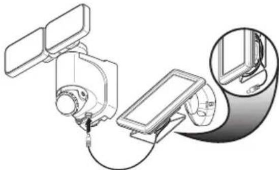
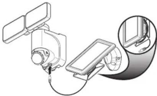
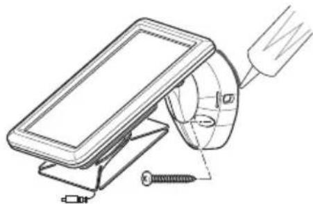
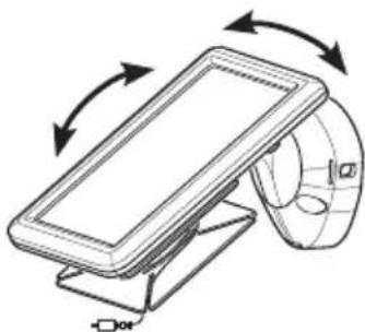
- Rotate the solar panel to the desired angle (see Figure 9).
IMPORTANT: The solar panel must receive as much direct sunlight over the course of the day as possible. Keep in mind that shadows may block the sunlight from reaching the solar panel during the day.
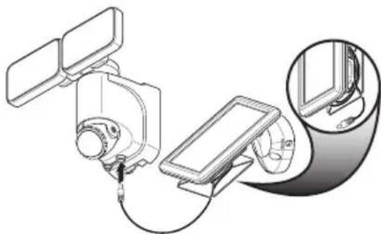
- Carefully route the solar panel cable to the light fixture. Remove the rubber plug from the bottom of the light fixture and insert the end of the cable into the opening (see Figure 10). Note: Wrap any excess solar panel cable around the cord management system located on the rear of the solar panel. Leave enough loose cable to form a drip loop.
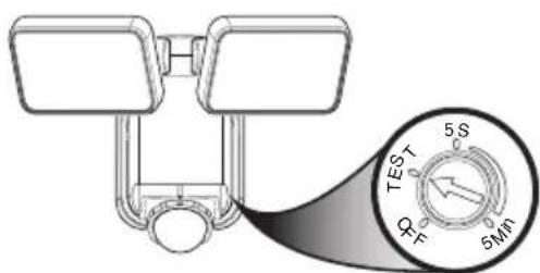
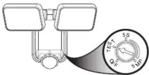
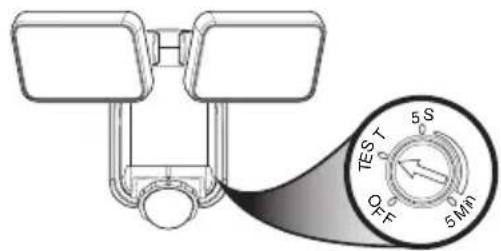
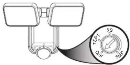
IMPORTANT: Turn the control dial on the side of the sensor to the OFF position and allow the battery to charge with 3 to 7 days of full sunshine before testing (see Figure 11).
OPERATION
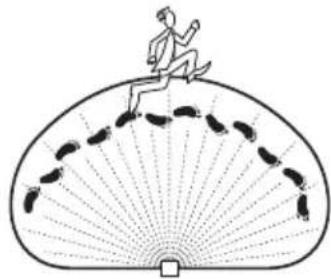
Determining the Motion Sensor Detection Zone
The motion sensor is non-adjustable. It has a sensing angle of 180^ and a range of approximately 40 ft. depending on the surrounding temperature. When the control dial is set to the “TEST” position, the light will operate during the day or night. The light will stay on for 5 seconds after all motion is stopped. The motion sensor will need to completely warm up (60 seconds) before beginning the setup process.
- Turn the control dial to the TEST position (see Figure 11).
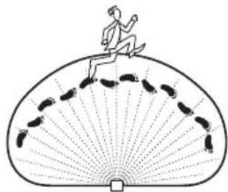
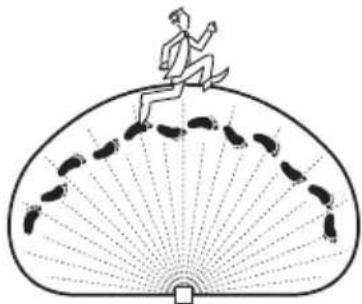
- Perform a "walk test": walk in an arc across the front of the motion sensor (see Figure 12).
- Watch the light. The light will come on indicating motion has been detected.
- Stop, wait for the light to turn off, and then begin walking again.
- Continue this process until the detection zone has been established.
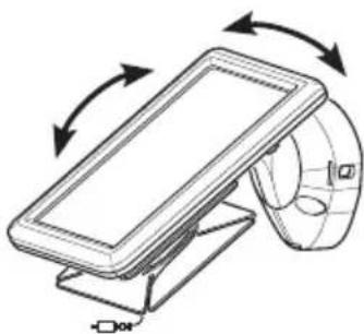
- If needed, gently grasp the lamp heads and move them from side to side or up and down to adjust the light coverage area.
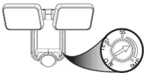
Adjusting the Light Timer
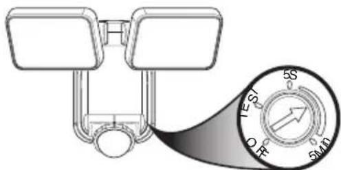
Turn the control dial to set the amount of time you want the lights to stay on after all motion has stopped (adjustble between 5 seconds and 5 minutes) (see Figure 13). Note: When set between 5 seconds and 5 minutes, the light fixture will only work after dark (sunset).
natural_image
Technical line drawing of a mechanical device with rotational arrows indicating motion (no text or symbols)Figure 9
natural_image
Technical line drawing of a mechanical device with attached components and a magnified inset showing internal detail (no text or symbols)Figure 10
text_image
TEST 5S ΦF 5MINFigure 11
natural_image
Illustration of a person running on a fan-shaped platform with footprints (no text or symbols)Figure 12
text_image
5S 5S 5MDFigure 13
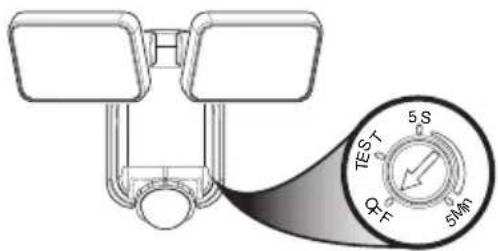
Using the OFF Control
Turn the control dial to the OFF position to turn the light off and to conserve the battery life (see Figure 14).
text_image
TEST 5S Φ F 6MFigure 14
CARE AND CLEANING
• To prolong the original appearance, clean the light fixture with clear water and a soft, damp cloth only.
- Do not use paints, solvents, or other chemicals on this light fixture. They could cause a premature deterioration of the finish. This is not a defect in the finish and will not be covered by the warranty.
- Do not spray the light fixture with a hose or power washer.
• To clean the camera lens, use a dry, microfiber cloth only.
SPECIFICATIONS
Range ....Up to 40 ft. (12 m) [varies with surrounding temperature].
Sensing Angle.....Up to 180°
Reserve Power Requirements......“C” Alkaline Batteries (3x) (not included)
Operating Modes ......OFF, TEST, TIMER
Timer 5 seconds to 5 minutes (adjustable)
Test Timer....8 Seconds
This device complies with Part 15 of the FCC Rules. Operation is subject to the following two conditions: (1) this device may not cause harmful interference, and (2) this device must accept any interference received, including interference that may cause undesired operation.
CAN ICES-005 (B) / NMB-005 (B)
TROUBLESHOOTING GUIDE
| SYMPTOM POSSIBLE CAUSE SOLUTION | ||
| The light will not come on. 1. | The control dial is set to the OFF position.2. Batteries are dead.3. Solar panel positioned wrong.4. Daylight turn-off (photocell) is in effect.5. Motion sensor is positioned wrong.6. Surrounding air temperature is greater than 122^ F (50^ C) or less than -4^ F (-20^ C) . | Turn the control dial to select an amount of time for the light timer.Replace the three “C” alkaline batteries.Position and angle solar panel so that it gets plenty of direct sunlight for most of the day, if not the entire day.Recheck after dark.Reposition light so motion sensor is positioned toward the area of movement.The light will operate normally inside the specified temperature range. |
| Light is not as bright as normal. | The rechargeable solar battery is low and the light is running off of the three “C” backup batteries. | Once the rechargeable solar battery is sufficiently recharged, the light will come on at full brightness. |
| There is a red blinking light inside the motion sensor. | The three “C” batteries are running low on power. | Replace the three “C” alkaline batteries. |
| The light comes on during the day. | Light control is mounted in a dark location.The motion sensor is in “TEST” mode. | Relocate light control to an area that receives more light.Turn the control dial between 5 seconds and 5 minutes. |
| The light comes on for no apparent reason. | Motion sensor may be sensing small animals or automobile traffic. | Reposition light so motion sensor is positioned away from the area of movement. |
| The lights flash on and off. 1. | Light control may be sensing shadows.The motion sensor is in “TEST” mode.The control dial is set to 5 seconds. | Relocate light to an area away from shadows.While in TEST mode, the light only stays on for 8 seconds. Set light timer control dial to desired time.Set the control dial to a longer time setting. |
TECHNICAL SERVICE
Please call 1-800-858-8501 (English speaking only) for assistance before returning product to store.
If you experience a problem, follow this guide. You may also want to visit our Web site at: www.hzsupport.com. If the problem persists, call* for assistance at 1-800-858-8501 (English speaking only), 8:00 AM to 5:00 PM CST (M-F). You may also write* to:
HeathCo LLC, P.O. Box 90045, Bowling Green, KY 42102-9045
ATTN: Technical Service
* If contacting Technical Service, please have the following information available: Model Number, Date of Purchase, and Place of Purchase.
No Service Parts Available for this Product
Please keep your dated sales receipt, it is required for all warranty requests.
THREE YEAR LIMITED WARRANTY
This is a “Limited Warranty” which gives you specific legal rights. You may also have other rights which vary from state to state or province to province.
For a period of three years from the date of purchase, any malfunction caused by factory defective parts or workmanship will be corrected at no charge to you.
Not Covered - Repair service, adjustment and calibration due to misuse, abuse or negligence, light bulbs, batteries, and other expendable items are not covered by this warranty. Unauthorized service or modification of the product or of any furnished component will void this warranty in its entirety. This warranty does not include reimbursement for inconvenience, installation, setup time, loss of use, unauthorized service, or return shipping charges.
This warranty covers only HeathCo LLC assembled products and is not extended to other equipment and components that a customer uses in conjunction with our products.
THIS WARRANTY IS EXPRESSLY IN LIEU OF ALL OTHER WARRANTIES, EXPRESS OR IMPLIED, INCLUDING ANY WARRANTY, REPRESENTATION OR CONDITION OF MERCHANTABILITY OR THAT THE PRODUCTS ARE FIT FOR ANY PARTICULAR PURPOSE OR USE, AND SPECIFICALLY IN LIEU OF ALL SPECIAL, INDIRECT, INCIDENTAL, OR CONSEQUENTIAL DAMAGES. REPAIR OR REPLACEMENT SHALL BE THE SOLE REMEDY OF THE CUSTOMER AND THERE SHALL BE NO LIABILITY ON THE PART OF HEATHCO LLC FOR ANY SPECIAL, INDIRECT, INCIDENTAL, OR CONSEQUENTIAL DAMAGES, INCLUDING BUT NOT LIMITED TO ANY LOSS OF BUSINESS OR PROFITS, WHETHER OR NOT FORESEEABLE. Some states or provinces do not allow the exclusion or limitation of incidental or consequential damages, so the above limitation or exclusion may not apply to you.
Please keep your dated sales receipt, it is required for all warranty requests.
HeathCo LLC reserves the right to discontinue products and to change specifications at any time without incurring any obligation to incorporate new features in products previously sold.
natural_image
Pure technical line drawing of a mechanical component without any text, numbers, or symbols7162
natural_image
Pure diagram of a piston-cranked mechanical component without any text or symbols7163/7164
natural_image
Pure line drawing of a mechanical component without any text, numbers, or symbolsnatural_image
Technical line drawing showing two views of a brick wall structure with a mounted fixture (no text or symbols)natural_image
Diagram of a device with internal components and directional arrows indicating assembly or operation (no text or symbols present)Figura 2
natural_image
Technical line drawing of a mechanical component with screws inserted (no text or symbols)Figura 3
natural_image
Technical line drawing of a mechanical device with screw fasteners and a tool (no text or symbols)Figura 8
natural_image
Technical diagram of a mechanical device with internal components and directional arrows indicating movement (no text or symbols)Figura 4

text_image
Technical diagram of a mechanical device with labeled parts and an inset magnified view showing internal components.Figura 5
natural_image
Technical line drawing of a mechanical device with rollers and a component, no visible text or symbolsFigura 6

natural_image
Diagram showing a mechanical component with a downward arrow pointing to a labeled electrical outlet (no text or symbols present)Figura 7
natural_image
Diagram of a device with rotating arrows indicating motion, no text or symbols presentFigura 9
natural_image
Diagram of a smart device with connected components and a magnified inset showing internal wiring (no text or symbols)Figura 10
text_image
TEST 5 S P 5 MINFigura 11
natural_image
Illustration of a person running on a fan-shaped path with footprints (no text or symbols)Figura 12
text_image
5S 5T 5MDFigura 13
Uso del control OFF
text_image
TEST 5S QF 5MNFigura 14
CUIDADO Y LIMPIEZA
Bowling Green, KY 42102-9045
ATTN: Technical Service (Servicio Técnico)
natural_image
Pure mechanical component diagram without any text, numbers, or symbols7162
natural_image
Pure diagram of two rectangular blocks connected by a U-shaped tube with a circular base (no text or symbols)7163/7164
natural_image
Pure mechanical component outline without any text, numbers, or symbolsDESCRIPTION
natural_image
Technical line drawing showing two structural components with brick walls and a hanging component (no text or symbols)natural_image
Diagram of a device with internal components and a close-up view showing internal structure (no text or symbols)Figure 2
natural_image
Technical line drawing of a mechanical component with screws and mounting holes (no text or symbols)Figure 3
natural_image
Technical diagram of a mechanical device with internal components and directional arrows indicating movement (no text or symbols)Figure 4
text_image
Technical diagram of a mechanical device with labeled parts and an inset magnified view showing internal components.Figure 5
natural_image
Technical line drawing of a mechanical device with rollers and a component, no visible text or symbolsFigure 6
natural_image
Diagram showing a mechanical component with a downward arrow pointing to a device (no text or symbols present)Figure 7
natural_image
Technical line drawing of a mechanical assembly with screw and nut components (no text or symbols)Figure 8
natural_image
Technical line drawing of a mechanical device with rotational arrows indicating motion (no text or symbols)Figure 9
natural_image
Technical line drawing of a mechanical device with attached components and a magnified inset showing internal detail (no text or symbols)Figure 10
UTILISATION
text_image
5S 5S OFF 5MPFigure 11
text_image
TEST 5S O F 5MnFigure 12
natural_image
Illustration of a person running on a fan-shaped platform with footprints (no text or symbols)Figure 13
text_image
TEST 5 S Φ π 5 MnFigure 14
ENTRETIEN ET NETTOYAGE
Bowling Green, KY 42102-9045
ATTN: Technical Service (Service technique)