5846 - Motion detector Heath Zenith - Free user manual and instructions
Find the device manual for free 5846 Heath Zenith in PDF.

User questions about 5846 Heath Zenith
0 question about this device. Answer the ones you know or ask your own.
Ask a new question about this device
Download the instructions for your Motion detector in PDF format for free! Find your manual 5846 - Heath Zenith and take your electronic device back in hand. On this page are published all the documents necessary for the use of your device. 5846 by Heath Zenith.
USER MANUAL 5846 Heath Zenith
Dated receipt required for warranty replacement.
FEATURES
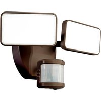
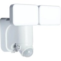
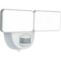
• Bright, energy saving LED light
• Automatically comes on when motion is detected.
UNPACKING
Be sure to remove all contents from packaging and verify all items are present before assembling this light fixture. This package includes the following items:
- Security Light
- Owner's Manual
- Mounting Hardware

natural_image
Technical line drawing of a mechanical component with two flanged parts and a central cylindrical feature (no text or symbols)HARDWARE INCLUDED
Note: Four mounting bracket screws are included. The installation will only require two. Discard the unused mounting bracket screws after installation.

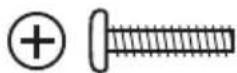
Plastic plug #6 Mounting Bracket #8 Mounting Bracket Wire Connector (x3) Screw (x2) Screw (x2)

natural_image
Simple line drawing of a screw with a curved head and a triangular shaft (no text or symbols)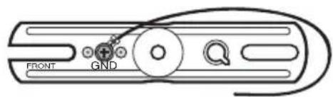
text_image
FRONT GNDMounting Bolt (Pre-Installed in Light Fixture) Mounting Bracket
IMPORTANT SAFETY AND INSTALLATION INFORMATION
Before installing security light, read all instructions carefully and keep owner's manual for future reference.
- WARNING: To prevent electric shock, ensure that the power is disconnected before installation.
- WARNING: Risk of fire. Keep the lamp heads at least 2 in. from combustible materials.
- CAUTION: To avoid water damage and the risk of electrical shock, the motion sensor controls must be facing the ground when the installation is complete.
- CAUTION: Burn hazard. Allow the light fixture to cool before touching.
- NOTICE: Do not connect this light fixture to a dimmer switch or timer.
• This light fixture requires 120-volts AC.
• This light fixture must be properly grounded. - Some electrical codes require installation by a qualified electrician.
- If you want to use Manual Mode, the light fixture must be wired through a switch.
- This fixture is designed for outdoor installation and should be mounted to a wall or eaves.
- To achieve best results, this fixture should be mounted 8 feet (2.4 meters) above the ground. Note: If fixture is mounted higher than 8 ft. (2.4 meters), aiming the sensor down will reduce coverage distance.
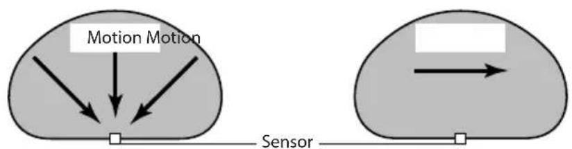
The motion sensor on this light fixture detects “motion” by the movement of heat across the coverage area. The motion sensor is more sensitive to the movement of heat moving across the coverage area and less sensitive to the movement of heat directly towards it.
flowchart
graph TD
    A["Input"] --> B["Motion Motion"]
    C["Sensor"] --> D["Output"]
    style A fill:#f9f,stroke:#333
    style C fill:#bbf,stroke:#333
Least Sensitive Most Sensitive
natural_image
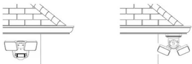
Technical line drawing showing two views of a ceiling-mounted security camera mounted on a wall, with no text or symbols present.Wall Mount Eave Mount
Note: Light fixture and sensor should be mounted as shown above when installed (depending upon type of installation).
WIRING

WARNING: Turn power off at circuit breaker or fuse.
Place tape over circuit breaker switch and verify power is off at the fixture.
- Remove the existing light fixture.
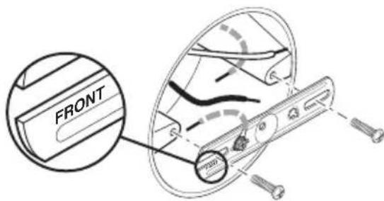
- Install the mounting bracket with the stamped word "FRONT" facing away from the junction box (see Figure 1). Use the mounting bracket screws that best fit the junction box.
-
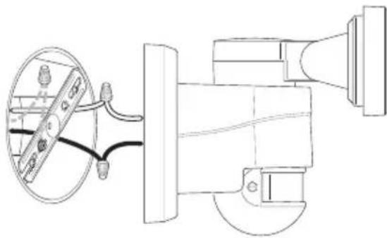
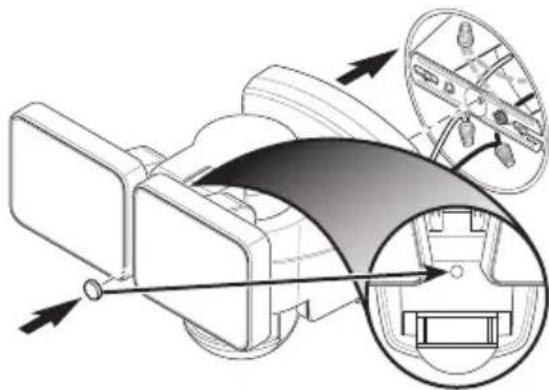
Attach the junction box ground wire to the ground wire attached to the mounting bracket using one of the wire connectors (see Figure 2).
-
Twist the junction box wires and fixture wires together as shown. Secure with wire connectors (see Figure 2).
- White to White
- Black to Black
- White to White - Black to Black
FINAL ASSEMBLY
-
Double check that all wiring connections are securely connected.
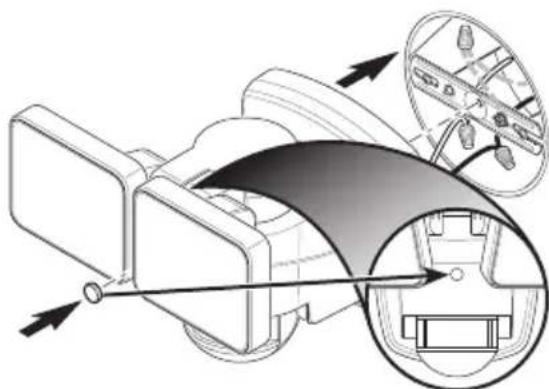
-
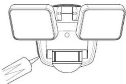
Align the mounting bolt on the back or the fixture with the center hole in the mounting bracket. Note: The mounting bolt is designed to stay in the light fixture.
-
Tighten the mounting bolt securely being careful not to overtighten (see Figure 3).
-
Double check that all wiring connections are securely connected.
- Align the mounting bolt on the back or the fixture with the center hole in the mounting bracket. Note: The mounting bolt is designed to stay in the light fixture.
- Tighten the mounting bolt securely being careful not to overtighten (see Figure 3).
IMPORTANT:
- If wall mounted, make sure the fixture is mounted with the sensor below the lamp heads.
-
If eave mounted, mount the fixture with sensor facing away from the house wall.
-
Push the rubber plug firmly into the mounting bolt hole on the light fixture (see Figure 3).
-
Caulk around mounting plate and mounting surface with silicone weather sealant (see Figure 4).
-
Push the rubber plug firmly into the mounting bolt hole on the light fixture (see Figure 3).
- Caulk around mounting plate and mounting surface with silicone weather sealant (see Figure 4).
TESTING AND ADJUSTMENTS

CAUTION: To avoid water damage and risk of electrical shock, motion sensor controls must be facing the ground when installation is complete.
- Turn on the circuit breaker and light switch.
Note: The motion sensor has a 1 minute warm up period before it will detect motion. When first turned on wait 1 minute.
text_image
FRONT 700Figure 1
natural_image
Technical line drawing of a mechanical device with a circular component and attached components (no text or symbols)Figure 2

natural_image
Diagram of a car interior showing steering wheel, dashboard, and steering wheel (no text or labels)Figure 3
natural_image
Technical line drawing of a mechanical component with two rectangular parts and a central bracket (no text or symbols)Figure 4
-
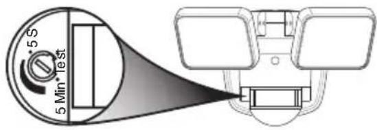
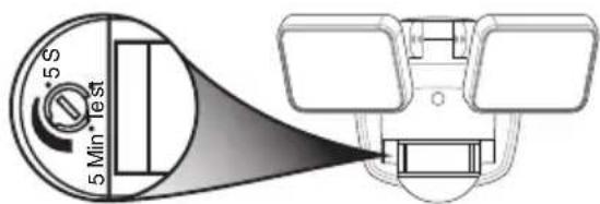
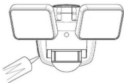
Turn the control dial to the TEST position (see Figure 5). Note: When the control dial is set to the TEST position, the light fixture will operate during the day or night. The light will stay on for 8 seconds after all motion has stopped.
-
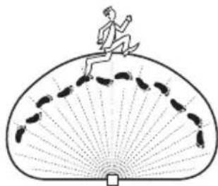
Walk through the coverage area noting where you are when the lights turn on. Also, the red LED behind the motion sensor lens will flash several times when motion is detected (see Figure 6).
-
Stop, wait for the light to turn off, and then begin walking again. Continue this process until the detection zone has been established.
-
If needed, gently grasp the motion sensor and move it from side to side or up and down to adjust the detection zone.
-
If needed, gently grasp the lamp heads and move them from side to side or up and down to adjust the light coverage area.
-
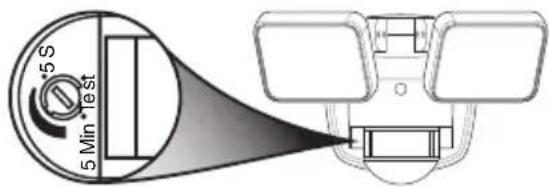
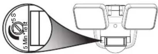
Turn the control dial to set the amount of time you want the lights to stay on after all motion has stopped (adjustble between 5 seconds and 5 minutes) (see Figure 7). Note: When set between 5 seconds and 5 minutes, the light fixture will only work after dark (sunset).
text_image
5 S 5 Min "testFigure 5
natural_image
Illustration of a person running on a fan with motion lines around (no text or symbols)Figure 6
text_image
5 S 5 Min TestFigure 7
IMPORTANT CONSIDERATIONS
AVOID AIMING THE SENSOR AT:
• Below are examples of objects that might produce heat and may cause the motion sensor to trigger:
- Pools of Water • Air Conditioners • Dryer Vents
• Animals • Heating Vents • Automobile Traffic
- Areas where pets or traffic may trigger the motion sensor.
- Nearby large, light-colored objects reflecting light may trigger the shut-off feature. Do not point other lights at the motion sensor.
SEASONAL CHANGES:
The motion sensor works by sensing temperature changes across its field of view. The closer the surrounding temperature is to a person's body heat, the less sensitive the sensor will appear. The greater the temperature difference, the more sensitive the sensor will appear. This is a normal part of the light sensor's operation.
MANUAL MODE
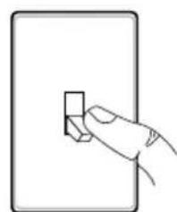
Manual mode overrides the motion sensor and timer control so the light will operate full bright. This feature only works at night and only for one night at a time. The motion sensor will reset to motion sensing mode at 6 hours or sunrise, whichever comes first. Manual mode can be toggled on and off using a wall switch.
- To turn manual mode on, switch the light off at the wall switch for 2 to 4 seconds and then back on.
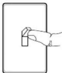
- To turn manual mode off, switch the light off at the wall switch for 2 to 4 seconds and then back on.
natural_image
Simple line drawing of a hand holding a small rectangular object on a rectangular surface (no text or symbols)Turn the switch OFF for 2 to 4 seconds
natural_image
Simple line drawing of a hand pressing a small object on a rectangular surface (no text or symbols)Turn the switch back ON
4 To see operational and troubleshooting information and videos,
go to www.hzsupport.com
208814-01
CARE AND CLEANING
- To prolong the original appearance, clean the light fixture with clear water and a soft, damp cloth only.
- Do not use paints, solvents, or other chemicals on this light fixture. They could cause a premature deterioration of the finish. This is not a defect in the finish and will not be covered by the warranty.
- Do not spray the light fixture with a hose or power washer.
• To clean the camera lens, use a dry, microfiber cloth only.
SPECIFICATIONS
Range....Up to 40 ft. (12 m) [varies with surrounding temperature].
Sensing Angle....Up to 180°
Power Requirements....120 VAC, 60 Hz
Operating Modes ......TEST, MOTION ACTIVATED, and MANUAL MODE
Timer 5 seconds to 5 minutes (adjustable)
Test Timer....8 Seconds
Manual Mode Timer......Maximum 6 Hours
This device complies with Part 15 of the FCC Rules. Operation is subject to the following two conditions: (1) this device may not cause harmful interference, and (2) this device must accept any interference received, including interference that may cause undesired operation.
CAN ICES-005 (B) / NMB-005 (B)
TROUBLESHOOTING GUIDE
| SYMPTOM POSSIBLE CAUSE SOLUTION | ||
| The light will not come on. 1 | Light switch is turned off.Fuse is blown or circuit breaker is turned off.Daylight turn-off (photocell) is in effect.The circuit wiring is incorrect, if this is a new installation.The motion sensor is aimed in the wrong direction.The outside air temperature is close to the same as a person's body heat. | Turn light switch on.Replace fuse or turn circuit breaker on.Recheck after dark.Verify wiring is correct.Re-aim the motion sensor to cover the desired area.See Seasonal Changes on page 4 for more information. |
| The light comes on during the day. | The motion sensor may be installed in a relatively dark location.The control dial is in the “TEST” position. | The light fixture is operating normally under these circumstances.Turn the control dial between 5 seconds and 5 minutes. |
| The light comes on for no apparent reason. | The motion sensor may be sensing small animals or automobile traffic.The outside temperature is much warmer or cooler than a person's body heat (summer or winter).The light fixture is wired through a dimmer or timer. | Reposition the motion sensor.See Seasonal Changes on page 4 for more information.Do not use a dimmer or timer to control the light fixture. Replace the dimmer or timer with a standard on/off wall switch. |
| The lights stay on continuously. | The motion sensor may be picking up a heat source like an air vent, dryer vent, or brightly painted, heat-reflective surface.The motion sensor is in manual mode.The light fixture is wired through a dimmer or timer.The light fixture is on the same circuit as a motor, transformer, or fluorescent bulb. | Reposition the motion sensor.Turn the control dial between 5 seconds and 5 minutes. Follow Manual Mode instructions on page 4 to reset.Do not use a dimmer or timer to control the light fixture. Replace the dimmer or timer with a standard on/off wall switch.Install the light fixture on a circuit without motors, transformers, or fluorescent bulbs. |
| The lights flash on and off. 1. | Heat or light from the lamp heads may be turning the motion sensor on and off.Heat is being reflected from other objects and may be turning the motion sensor on and off.The motion sensor is in “TEST” mode and warming up. | Reposition the lamp heads away from the motion sensor.Reposition the motion sensor.While in TEST mode, the light only stays on for 8 seconds. Turn the control dial between 5 seconds and 5 minutes. |
| The lights flash once then stay off in manual mode. | The motion sensor is detecting light from the lamp heads. | Reposition the lamp heads to keep the area below the motion sensor relatively dark. |
TECHNICAL SERVICE
Please call 1-800-858-8501 (English speaking only) for assistance before returning product to store.
If you experience a problem, follow this guide. You may also want to visit our Web site at: www.hzsupport.com. If the problem persists, call* for assistance at 1-800-858-8501 (English speaking only), 8:00 AM to 5:00 PM CST (M-F). You may also write* to:
HeathCo LLC, P.O. Box 90045, Bowling Green, KY 42102-9045
ATTN: Technical Service
* If contacting Technical Service, please have the following information available: Model Number, Date of Purchase, and Place of Purchase.
No Service Parts Available for this Product
Please keep your dated sales receipt, it is required for all warranty requests.
FIVE YEAR LIMITED WARRANTY
This is a “Limited Warranty” which gives you specific legal rights. You may also have other rights which vary from state to state or province to province.
For a period of five years from the date of purchase, any malfunction caused by factory defective parts or workmanship will be corrected at no charge to you.
Not Covered - Repair service, adjustment and calibration due to misuse, abuse or negligence, light bulbs, batteries, and other expendable items are not covered by this warranty. Unauthorized service or modification of the product or of any furnished component will void this warranty in its entirety. This warranty does not include reimbursement for inconvenience, installation, setup time, loss of use, unauthorized service, or return shipping charges.
This warranty covers only HeathCo LLC assembled products and is not extended to other equipment and components that a customer uses in conjunction with our products.
THIS WARRANTY IS EXPRESSLY IN LIEU OF ALL OTHER WARRANTIES, EXPRESS OR IMPLIED, INCLUDING ANY WARRANTY, REPRESENTATION OR CONDITION OF MERCHANTABILITY OR THAT THE PRODUCTS ARE FIT FOR ANY PARTICULAR PURPOSE OR USE, AND SPECIFICALLY IN LIEU OF ALL SPECIAL, INDIRECT, INCIDENTAL, OR CONSEQUENTIAL DAMAGES, REPAIR OR REPLACEMENT SHALL BE THE SOLE REMEDY OF THE CUSTOMER AND THERE SHALL BE NO LIABILITY ON THE PART OF HEATHCO LLC FOR ANY SPECIAL, INDIRECT, INCIDENTAL, OR CONSEQUENTIAL DAMAGES, INCLUDING BUT NOT LIMITED TO ANY LOSS OF BUSINESS OR PROFITS, WHETHER OR NOT FORESEEABLE. Some states or provinces do not allow the exclusion or limitation of incidental or consequential damages, so the above limitation or exclusion may not apply to you.
Please keep your dated sales receipt, it is required for all warranty requests.
HeathCo LLC reserves the right to discontinue products and to change specifications at any time without incurring any obligation to incorporate new features in products previously sold.
Heath Zenith
natural_image
Technical line drawing of a mechanical component with two flanged parts and a central cylindrical feature (no text or symbols)FERRETERÍA INCLUIDA
natural_image
Simple line drawing of a bolt with a curved head and threaded end (no text or symbols)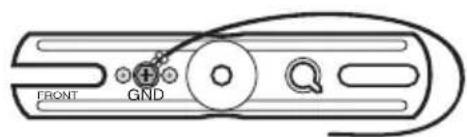
text_image
FRONT GNDnatural_image
Technical line drawing showing two views of a ceiling-mounted security camera mounted on a wall (no text or symbols)natural_image
Technical line drawing of a mechanical device with a circular component and attached components (no text or symbols)Figura 2
natural_image
Technical diagram of a car interior showing steering wheel, dashboard, and steering wheel (no text or labels)Figura 3
natural_image
Technical line drawing of a mechanical component with two rectangular parts and a central bracket (no text or symbols)Figura 4
PRUEBAS Y AJUSTES

natural_image
Illustration of a person running on a fan-shaped path with footprints (no text or symbols)Figura 6
text_image
5 S 5 Min -estFigura 7
natural_image
Simple line drawing of a hand pressing a small rectangular object on a rectangular surface (no text or symbols)natural_image
Simple line drawing of a hand pressing a button on a rectangular panel (no text or symbols)Bowling Green, KY 42102-9045
ATTN: Technical Service (Servicio Técnico)
natural_image
Technical line drawing of a mechanical component with two flanged parts and a central cylindrical feature (no text or symbols)QUINCAILLERIE FOURNIE
natural_image
Simple line drawing of a bolt with a curved head and threaded end (no text or symbols)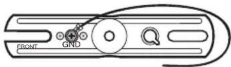
text_image
FRONT GNDnatural_image
Technical line drawings of ceiling-mounted security camera and wall-mounted camera (no text or symbols)natural_image
Technical line drawing of a mechanical device with internal components and a magnified inset showing a circular component (no text or symbols)Figure 2
natural_image
Technical diagram of a vehicle's internal components and steering wheel (no text or labels)Figure 3

natural_image
Technical line drawing of a mechanical component with two upright plates and a central bracket (no text or symbols)Figure 4
ESSAIS ET RÉGLAGES

natural_image
Illustration of a person running on a fan-shaped platform with footprints, no text or symbols presentFigure 6
text_image
5 S 5 Min -estFigure 7
RENSEIGNEMENTS IMPORTANTS
natural_image
Simple line drawing of a hand holding a small rectangular object (no text or symbols)natural_image
Simple line drawing of a hand pressing a button on a rectangular panel (no text or symbols)Bowling Green, KY 42102-9045
ATTN: Technical Service (Service technique)
Staple Purchase Receipt Here