4305 - Motion detector Heath Zenith - Free user manual and instructions
Find the device manual for free 4305 Heath Zenith in PDF.

User questions about 4305 Heath Zenith
0 question about this device. Answer the ones you know or ask your own.
Ask a new question about this device
Download the instructions for your Motion detector in PDF format for free! Find your manual 4305 - Heath Zenith and take your electronic device back in hand. On this page are published all the documents necessary for the use of your device. 4305 by Heath Zenith.
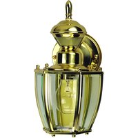
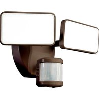
USER MANUAL 4305 Heath Zenith
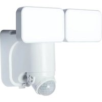
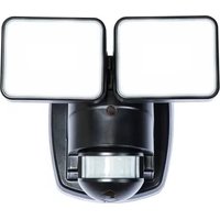
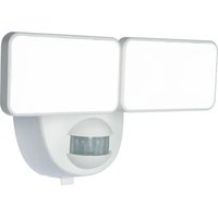
• Light comes on when motion is detected.
• Automatically turns light off.
- Photocell keeps the light off during daylight hours.
This package includes:
- Porch Light
- Easy to use Universal Mounting Bracket
- Mounting Hardware
- Wire Nuts
- Lens Shield
REQUIREMENTS
- The light control requires 120 volts AC.
- If you want to use Manual Mode, the control must be wired through a switch.
- Some electrical codes require installation by a qualified electrician.
Before installation, record the model number listed inside the fixture. Attach receipt in case of possible warranty issues.
Model Number:
OPERATION
| Mode: On-Time Works: Day Night | |||
| Test | 5 Seconds | x | x |
| Auto | 1, 5, or 10 Min | x | |
| Manual | To Dawn* | x | |
* resets to Auto Mode at dawn.
Note: When first turned on wait about 1 12 minutes for the circuitry to calibrate.
TEST
Set the ON-TIME switch on the sensor to TEST.
ON-TIME

TEST 1510MIN
AUTO
Set ON-TIME switch to 1, 5, or 10 minutes.
ON-TIME

MANUAL MODE
Manual mode only works at night because daylight returns the sensor to AUTO.
Flip the light switch off for one second then back on to toggle between AUTO and MANUAL MODE.
Manual mode works only with the ON-TIME switch in the 1, 5, or 10 position.
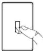
1 Second OFF then...
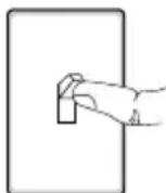
... back on.
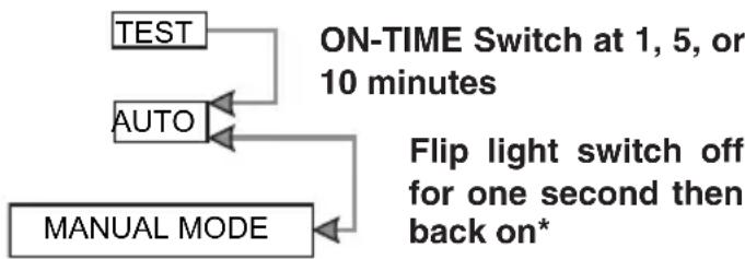
MODE SWITCHING SUMMARY
flowchart
graph TD
    A["TEST"] --> B["ON-TIME Switch at 1, 5, or 10 minutes"]
    C["AUTO"] --> B
    D["MANUAL MODE"] --> B
    B --> E["Flip light switch off for one second then back on*"]
* If you get confused while switching modes, turn the power off for one minute, then back on. After the calibration time the control will be in the AUTO mode.
DISASSEMBLE LIGHT FIXTURE
- Remove two decorative nuts from light fixture cover.
- Remove cover from base.
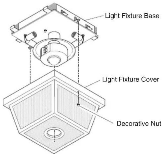
text_image
Light Fixture Base Light Fixture Cover Decorative Nut- Remove two decorative nuts from fixture screws in universal mounting bracket.
- Remove universal mounting bracket from base.
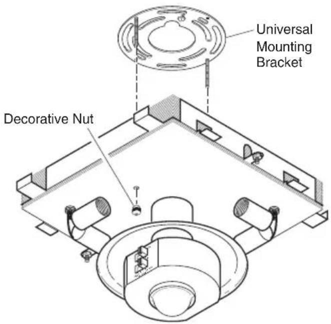
text_image
Universal Mounting Bracket Decorative NutINSTALL UNIVERSAL MOUNTING BRACKET
For best performance, mount the fixture at least 8 feet (2.4 m) above the ground.

WARNING: Turn power off at circuit ker or fuse.
- Tighten the two fixture screws finger tight.
- Attach universal mounting bracket to junction box securely with the two screws provided.
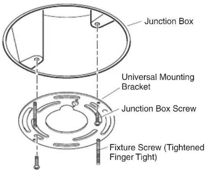
text_image
Junction Box Universal Mounting Bracket Junction Box Screw Fixture Screw (Tightened Finger Tight)WIRING LIGHT FIXTURE
- Connect the junction box wires and the fixture wires together as shown in the following diagrams.

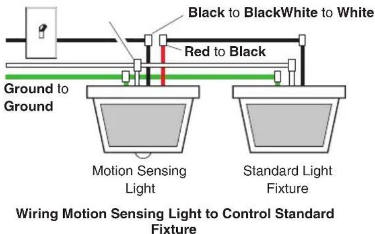
CAUTION: DO NOT remove wire connec- from RED wire or connect the RED wire less you want to control other lights from motion sensor fixture.
- Twist and secure wires with wire nuts.

natural_image
Simple line drawing of a pair of wires connected to a bulb (no text or symbols)Note: If you have a metal junction box use the recommended grounding method shown in the following illustration. If you are uncertain about the grounding method, consult your local building code.
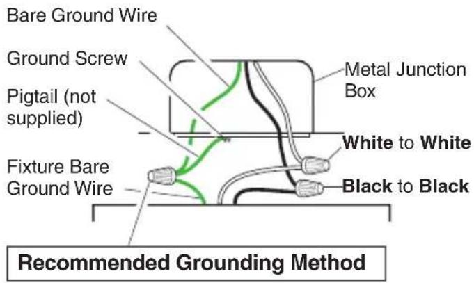
text_image
Bare Ground Wire Ground Screw Pigtail (not supplied) Fixture Bare Ground Wire Metal Junction Box White to White Black to Black Recommended Grounding Method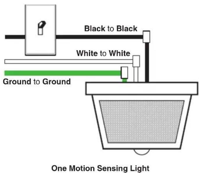
text_image
Black to Black White to White Ground to Ground One Motion Sensing Light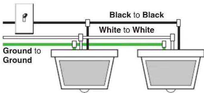
text_image
Black to Black White to White Ground to GroundTwo Motion Sensing Lights (Working Independently)
Other Wiring Options
This fixture can be wired to control another standard or motion sensing light fixture(s). See the following wiring diagrams for proper connections.
Note: All wiring should be run in accordance with the National Electrical Code through conduit or another acceptable means. Contact a qualified electrician if there is any question as to the suitability of the system.
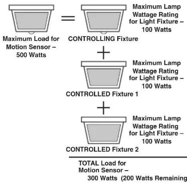
When controlling an additional light fixture(s), the maximum wattage of the motion sensor on this fixture should be observed. See illustration below for an example of a maximum lamp wattage load calculation.
flowchart
graph TD
    A["Maximum Load for Motion Sensor - 500 Watts"] --> B["CONTROLLING Fixture"]
    B --> C["+"]
    C --> D["CONTROLLED Fixture 1"]
    D --> E["+"]
    E --> F["CONTROLLED Fixture 2"]
    F --> G["TOTAL Load for Motion Sensor - 300 Watts (200 Watts Remaining)"]
    style A fill:#f9f,stroke:#333
    style B fill:#f9f,stroke:#333
    style C fill:#f9f,stroke:#333
    style D fill:#f9f,stroke:#333
    style E fill:#f9f,stroke:#333
    style F fill:#f9f,stroke:#333
    style G fill:#ccf,stroke:#333
IMPORTANT: When determining the maximum lamp wattage rating of the fixture to be controlled, refer to the maximum lamp wattage label on the fixture and not the wattage rating on the lamp(s) currently installed in the fixture.
text_image
Black to BlackWhite to White Red to Black Ground to Ground Motion Sensing Light Standard Light Fixture Wiring Motion Sensing Light to Control Standard Fixture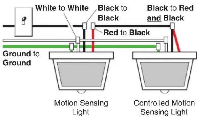
text_image
White to White Black to Black Red to Black Black to Red and Black Ground to Ground Motion Sensing Light Controlled Motion Sensing LightWiring Motion Sensing Light to Control Another Motion Sensing Light
It is also possible to wire two motion sensing lights so that either unit will turn on both lights at the same time (dual controlled system). It is recommended that only people with electrical wiring experience attempt this configuration. Please call our customer service number (1-800-858-8501) before attempting this wiring. If the dual controlled wiring is not done correctly, it can destroy both motion sensing fixtures and void your warranty.
INSTALL FIXTURE BASE TO JUNCTION BOX
- Push wires into the junction box.
- Slide light fixture base onto fixture screws and tighten decorative nuts snugly against the base.
- Install four candelabra base light bulbs (25 Watts maximum each).
- Refer to TESTING section before installing cover.
- After switches are set and testing is complete, use the 2 decorative nuts to install the cover.
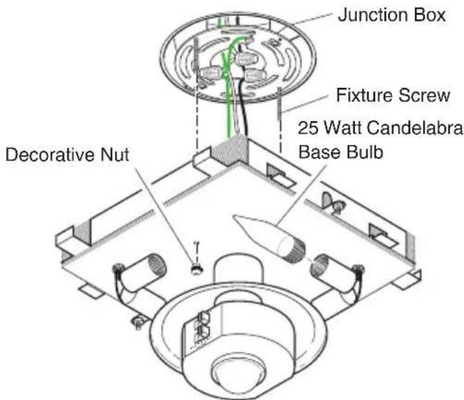
text_image
Junction Box Fixture Screw 25 Watt Candelabra Base Bulb Decorative NutTESTING
- Turn on the circuit breaker and light switch.
Note: Sensor has a 1 12 minute warm up period before it will detect motion. When first turned on wait 1 12 minutes.
- Set the SENSITIVITY switch to the "M" position and the ON-TIME switch to the TEST position.
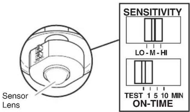
text_image
Sensor Lens SENSITIVITY LO - M - HI TEST 1 5 10 MIN ON-TIME- Walk through the coverage area noting where you are when the lights turn on. In TEST mode, light will stay on for only 5 seconds then turn off.
- Adjust the SENSITIVITY to increase or decrease the range as needed. Too much sensitivity may cause false triggering due to heat sources in the coverage area (see Adjustment of Coverage Area or Troubleshooting section).
- Set the amount of TIME you want the light to stay on after motion is detected (1, 5, or 10 minutes).
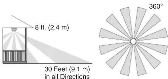
text_image
8 ft. (2.4 m) 30 Feet (9.1 m) in all Directions 360°Maximum Range Coverage Angle* (Top View)
* Without lens shield installed.
The sensor is less sensitive to motion directly towards it and more sensitive to motion across coverage area.
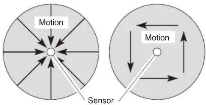
text_image
Motion Sensor MotionLeast Sensitive Most Sensitive
Adjustment of Coverage Area
The sensor on this light fixture detects “motion” by the movement of heat (body heat) across the coverage area. However, following are examples of objects that also produce heat and can cause the sensor to false trigger:
- Pools of Water • Air Conditioners
- Dryer Vents • Fenced-In Animals
• Heating Vents • Automobile Traffic
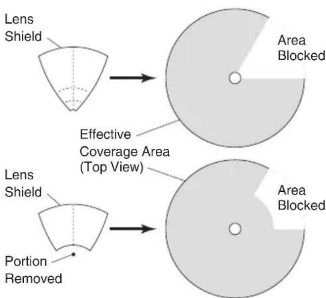
If you suspect that a heat source of this type is falsely triggering the sensor and reducing the sensitivity does not solve the problem, then a lens shield (included) can be installed. The plastic lens shield is divided into 6 sections. Each section will reduce the coverage angle by 30 degrees. Also, the tip of each section may be removed to change the effective range of the sensor.
text_image
Lens Shield Effective Coverage Area (Top View) Lens Shield Portion Removed Area Blocked Area Blocked204063-02
- Break off the amount of lens shield needed to block the desired area of coverage.
- Cut desired amount of foam tape needed to adhere the lens shield to the sensor lens.
- Remove paper backing from one side of cut foam tape and adhere foam tape to inside of lens shield.
- Remove paper backing from other side of cut foam tape and adhere lens shield to sensor lens.
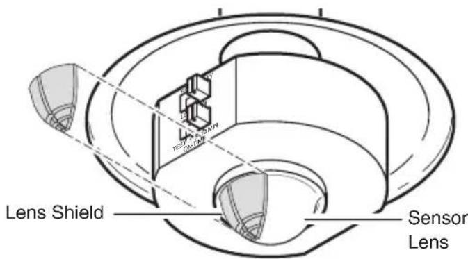
text_image
Lens Shield Sensor Lens- Retest to confirm that the sensor is no longer false triggering.
Note: To help determine amount of lens shield required, apply small sections one at a time. Additional sections can be applied if necessary.
SPECIFICATIONS
Range....Up to 30 ft. (9.1 m) [varies with surrounding temperature].
Sensing Angle ....360°
Electrical Load.....Up to 100 Watt Maximum Tungsten Incandescent (Up to 25 Watt Maximum each lamp holder).
Bulb Type......Candelabra Base, Type "B", 25 Watt Maximum
Sensor Capacity ....Up to 500 Watt (4.2 A.) Maximum Tungsten Incandescent
Power Requirements ....120 VAC, 60 Hz
Operating Modes......TEST, AUTO, and MANUAL MODE
ON-Timer....1, 5, 10 minutes
TROUBLESHOOTING GUIDE
| SYMPTOM | POSSIBLE CAUSE |
| Light will not come on. | 1. Light switch is turned off.2. Bulbs are loose or burned out.3. Fuse is blown or circuit breaker is turned off.4. Daylight turn-off is in effect (re-check after dark).5. Incorrect circuit wiring, if this is a new installation. |
| Light comes on in daylight. | 1. Sensor may be installed in a relatively dark location.2. Sensor is in Test. (Set control switch to an ON-TIME position.) |
| Light comes on for no apparent reason. | 1. Sensor may be sensing small animals or automobile traffic. (Reduce sensitivity.)2. Sensitivity is set too high. (Reduce sensitivity.) |
| SYMPTOM | POSSIBLE CAUSE |
| Light stays on continuously. | 1. There is a heat source like an air vent, dryer vent, or brightly-painted, heat-reflective surface in the coverage area. (Install shield on sensor in the direction of heat source.)2. Sensor is in Manual Mode. (Switch to Auto.)3. Sensitivity is set too high. (Reduce sensitivity.) |
| Light flashes on and off. | 1. Heat being reflected from other objects may be affecting the sensor. (Reduce sensitivity.)2. Sensor is in the Test mode. (While in TEST mode, light only stays on for 5 seconds.) |
| Light does not stay on in Manual mode. | 1. Nearby large, light-colored objects reflecting light may trigger the shut-off feature. Do not point other lights at the sensor. |
This device complies with Part 15 of the FCC Rules. Operation is subject to the following two conditions: (1) this device may not cause harmful interference, and (2) this device must accept any interference received, including interference that may cause undesired operation.
CAN ICES-3 (B)/NMB-3(B)
TECHNICAL SERVICE
Please call 1-800-858-8501 (English speaking only) for assistance before returning product to store.
If you experience a problem, follow this guide. You may also want to visit our Web site at: www.hzsupport.com. If the problem persists, call* for assistance at 1-800-858-8501 (English speaking only), 8:00 AM to 5:00 PM CST (M-F). You may also write* to:
HeathCo LLC
P.O. Box 90045
Bowling Green, KY 42102-9045
ATTN: Technical Service
* If contacting Technical Service, please have the following information available: Model Number, Date of Purchase, and Place of Purchase.
No Service Parts Available for this Product
Please keep your dated sales receipt, it is required for all warranty requests.
TWO YEAR LIMITED WARRANTY
This is a “Limited Warranty” which gives you specific legal rights. You may also have other rights which vary from state to state or province to province.
For a period of two years from the date of purchase, any malfunction caused by factory defective parts or workmanship will be corrected at no charge to you.
Not Covered - Repair service, adjustment and calibration due to misuse, abuse or negligence, light bulbs, batteries, and other expendable items are not covered by this warranty. Unauthorized service or modification of the product or of any furnished component will void this warranty in its entirety. This warranty does not include reimbursement for inconvenience, installation, setup time, loss of use, unauthorized service, or return shipping charges.
This warranty covers only HeathCo LLC assembled products and is not extended to other equipment and components that a customer uses in conjunction with our products.
THIS WARRANTY IS EXPRESSLY IN LIEU OF ALL OTHER WARRANTIES, EXPRESS OR IMPLIED, INCLUDING ANY WARRANTY, REPRESENTATION OR CONDITION OF MERCHANTABILITY OR THAT THE PRODUCTS ARE FIT FOR ANY PARTICULAR PURPOSE OR USE, AND SPECIFICALLY IN LIEU OF ALL SPECIAL, INDIRECT, INCIDENTAL, OR CONSEQUENTIAL DAMAGES.
REPAIR OR REPLACEMENT SHALL BE THE SOLE REMEDY OF THE CUSTOMER AND THERE SHALL BE NO LIABILITY ON THE PART OF HEATHCO LLC FOR ANY SPECIAL, INDIRECT, INCIDENTAL, OR CONSEQUENTIAL DAMAGES, INCLUDING BUT NOT LIMITED TO ANY LOSS OF BUSINESS OR PROFITS, WHETHER OR NOT FORESEEABLE. Some states or provinces do not allow the exclusion or limitation of incidental or consequential damages, so the above limitation or exclusion may not apply to you.
Please keep your dated sales receipt, it is required for all warranty requests.
HeathCo LLC reserves the right to discontinue products and to change specifications at any time without incurring any obligation to incorporate new features in products previously sold.
Heath Zenith
natural_image
Simple line drawing of a tube being inserted into a bulb (no text or symbols)natural_image
Technical line drawing of a mechanical component with no visible text or symbolsPlaca traslúcida del detector
Bowling Green, KY 42102-9045
ATTN: Technical Service (Servicio Técnic)
natural_image
Simple line drawing of a hairpin with a curved cord (no text or symbols)Bowling Green, KY 42102-9045
ATTN: Technical Service (Service technique)
Date of Purchase: ____
Staple Purchase Receipt Here