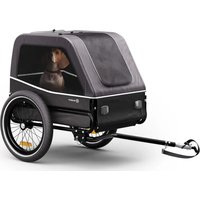
Goldie S - Bike trailer Klarfit - Free user manual and instructions
Find the device manual for free Goldie S Klarfit in PDF.


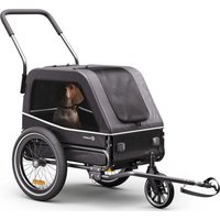
| Product type | Dog bicycle trailer |
| Brand | Klarfit |
| Model | Goldie S |
| Category | Bicycle trailer |
| Maximum load weight | 23 kg |
| Recommended maximum speed (smooth road) | 16 km/h |
| Recommended maximum speed (curves/rough terrain) | 8 km/h |
| Number of wheels | 2 (standard model) / 3 (hybrid model with stroller kit) |
| Hitch type | Universal (quick-release axle or solid axle; not for thru-axle) |
| Parking brake | On hybrid models (item numbers 10045937 and 10045938) |
| Stroller kit included | On hybrid models (handle + front wheel) |
| Reflectors | White front, red rear |
| Safety flag | Yes |
| Fabric material | Hand washable (warm water, mild soap) |
| Window cleaning | Soft damp cloth |
| Storage temperature range | -23°C to 65°C |
| Weight on hitch (loaded trailer) | Between 3 kg and 8 kg |
| Minimum cyclist age | 16 years |
| Suitable for dogs size | Up to 67 cm body length and 50 cm shoulder height |
Frequently Asked Questions - Goldie S Klarfit
User questions about Goldie S Klarfit
0 question about this device. Answer the ones you know or ask your own.
Ask a new question about this device
Download the instructions for your Bike trailer in PDF format for free! Find your manual Goldie S - Klarfit and take your electronic device back in hand. On this page are published all the documents necessary for the use of your device. Goldie S by Klarfit.
USER MANUAL Goldie S Klarfit
INHALTSVERZEICHNIS
Hersteller & Importeur (UK) 1
Berlin Brands Group UK Limited
PO Box 42
272 Kensington High Street
London, W8 6ND
United Kingdom
LIEFERUMFANG 10045935, 10045936
natural_image
Pure technical line drawing of a mechanical component or bracket (no text or symbols)natural_image
Line drawing of two bicycle wheels with spokes and wheel rim (no text or symbols)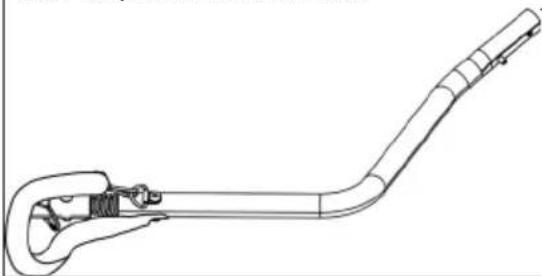
natural_image
Line drawing of a mechanical tool or device with a curved handle and attached bracket (no text or symbols)natural_image
Technical line drawing of a metal bracket with multiple circular components and a coiled cable (no text or symbols)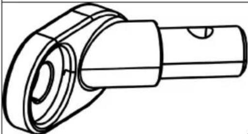
natural_image
Technical line drawing of a mechanical component with cylindrical and flanged sections (no text or symbols)1 x Universalkupplung 1 x Fahne
natural_image
Simple line drawing of a right triangle connected to a horizontal line with a curved base (no text or symbols)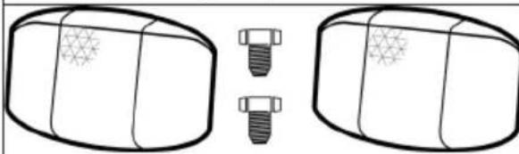
natural_image
Diagram showing two cylindrical objects with star patterns, each with a separate screw and bolt (no text or symbols)natural_image
Diagram showing two cylindrical objects with star patterns, each with a separate screw and a separate bolt (no text or symbols)Werkzeuge
natural_image
Simple line drawing of a wrench (no text or symbols)11 mm Schraubenschlüssel Inbusschlüssel
natural_image
Simple line drawing of a bent pipe or angle (no text or symbols)LIEFERUMFANG 10045937, 10045938
natural_image
Pure technical line drawing of a mechanical component or bracket (no text or symbols)natural_image
Two bicycle wheel rim designs with spokes and hub, no text or symbols present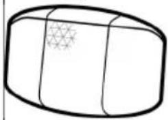
natural_image
Simple line drawing of a 3D rectangular object with a grid pattern on its surface (no text or symbols)
natural_image
Simple line drawing of a 3D rectangular block with a grid pattern on one side (no text or symbols)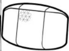
natural_image
Simple line drawing of a cylindrical object with a star pattern on its side (no text or symbols)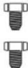
natural_image
Simple line drawing of a cylindrical object with a star-like pattern on its surface (no text or symbols)natural_image
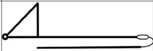
Line drawing of a handheld tool or device with a curved handle and handle (no text or symbols)1 x Zugstange 1 x Fahne
natural_image
Simple line drawing of a right triangle and a horizontal line with a curved end (no text or symbols)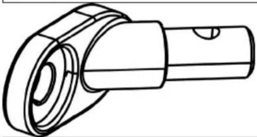
natural_image
Technical line drawing of a mechanical component with no visible text or symbolsnatural_image
Technical line drawing of a mechanical bracket with bolts and a coiled cable (no text or symbols)
natural_image
Simple line drawing of a mechanical component with three pins (no text or symbols)
natural_image
Simple line drawing of a three-pin key with a handle and screw base (no text or symbols)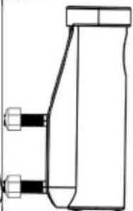
natural_image
Pure mechanical component diagram without any text, numbers, or symbols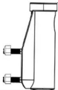
natural_image
Pure technical line drawing of a mechanical component with no text or symbolsnatural_image
Technical line drawing of a car wheel assembly with four spokes and a handle (no text or symbols)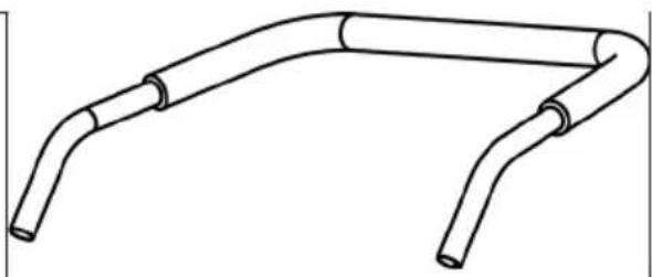
natural_image
Line drawing of a U-shaped pipe or conduit with two cylindrical ends (no text or symbols)natural_image
Simple line drawing of a wrench (no text or symbols)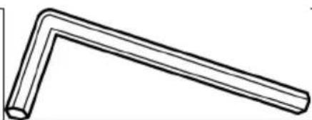
natural_image
Simple line drawing of a bent pipe or angle (no text or symbols)11 mm Schraubenschlüssel 4 mm Inbusschlüssel
ZUSAMMENBAU
natural_image
Technical line drawing of a mechanical component with red arrows indicating motion or force direction (no text or symbols)Abbildung 1
2. Attaching the wheels
natural_image
Technical line drawing of a mechanical assembly with rollers and components (no text or symbols)Abbildung 9
natural_image
Technical line drawing showing two mechanical assembly steps with arrows indicating motion (no text or symbols)Abbildung 10
natural_image
Technical line drawing of a mechanical assembly with hoses and connectors (no text or symbols)natural_image
Mechanical diagram showing a car suspension system with tire, bracket, and valve mechanism (no text or labels)natural_image
Technical line drawing of a mechanical assembly with no visible text or symbolsAbbildung 13
WARNUNG!
natural_image
Mechanical linkage diagram showing a chain with joints and links (no text or symbols)Abbildung 14
WARNUNG!
natural_image
Mechanical assembly diagram showing a motor and gear mechanism with no visible text or symbols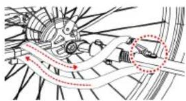
natural_image
Mechanical assembly diagram showing gear and shaft components with motion arrows (no text or labels)Abbildung 15
VOR DER FAHRT
Congratulations on purchasing this product. Please read this manual carefully and take care of the following hints on installation and use to avoid technical damages. Any failure caused by ignoring the items and cautions mentioned in the operation and installation instructions are not covered by our warranty and any liability. Scan the QR code to get access to the latest user manual and more product information.

CONTENTS
Manufacturer & Importer (UK) 16
Safety Instructions 17
Choose the right size of trailer 18
Parts in Package 10045935, 10045936 19
Parts in Package 10045937, 10045938 20
Assembly 22
Attaching Trailer to Bicycle 26
Before you ride 28
Care and Maintenance 28
TECHNICAL DATA
| Item number Goldie Small 10045935, | 10045936 |
| Item number Goldie Small Hybrid 10045937, | 10045938 |
| Permissible load 23 kg | |
| Recommended maximum speed 16 km/h |
MANUFACTURER & IMPORTER (UK)
Manufacturer:
Chal-Tec GmbH, Wallstrasse 16, 10179 Berlin, Germany.
Importer for Great Britain:
Berlin Brands Group UK Limited
PO Box 42
272 Kensington High Street
London, W8 6ND
United Kingdom

WARNING!
Danger of serious injury or death
Do read instructions before driving. Failure to comply with the instructions and warnings in this manual could result in serious injury or death.
- Consult your vet to make sure it is safe for your pet to ride in a trailer.
- Ensure that your pet cannot come into contact with the wheel spokes.
- Check your pet's comfort and safety frequently, especially in hot or cold weather.
- Never leave your pet unattended and ALWAYS HOLD THE TRAILER/STROLLER FROM TURNING BACK WHEN YOUR PET ENTERS OR EXITS THE TRAILER.
- DO NOT use with a total load exceeding 50 lbs (23 kg).
- Never use the pet trailer to transport children or cargo.
- DO NOT make any modifications to the product. Any packages placed on the trailer may cause the trailer to become unstable.
- DO NOT over-inflate the tyres. Failure to maintain the rated pressure on the tyre sidewall may result in tyre explosion and possible injury.
- Before every ride, check that the trailer does not interfere with the braking, pedalling or steering of the bicycle.
- Always obey local regulations when using the trailer on public roads.
- Never ride at night without adequate lighting. Comply with all local lighting regulations.
- When using your trailer, you are towing extra weight and a larger vehicle. You will need to allow more time for braking, slowing down, stopping and starting, and more room for turning and passing. Experiment with the loaded trailer in an uncongested area until you are familiar with how your motorcycle handles when towing a trailer.
- Avoid rocks, kerbs, hard braking and sudden swerving. Avoid driving over obstacles with one wheel as this may cause the trailer to tip over.
- Always ride with the front and rear doors fully closed to protect your pet from flying debris and to prevent your pet from jumping off the trailer.
- The rider must be at least 16 years old.
- Recommended speed limits:
- 10 mph (16 km/h) on smooth, straight roads
- 5 mph (8 km/h) when turning or on uneven surfaces.
- The weight of the trailer must be properly distributed for safe handling. The weight on the hitch should be between 30 N (≈6.6 lbs. or 3 kg) and 80 N (≈17.6 lbs. or 8 kg). To measure this, load your trailer and place it next to a bathroom scale. Step on the scale and note your weight. While standing on the scale, lift the end of the hitcharm one foot (approx. 25 cm) off the ground. If the weight is too low, the rear wheel of the bicycle may lose traction. If it is too high, the hitch may be overloaded.
WARNING!
Danger of serious injury or death
Never overload the trailer and never ride with a tow bar load that is outside the specified range of 6.6 to 17.6 lbs. (3 - 8 kg). Always distribute the load evenly. Failure to do so could result in accidents with serious injury or death.
CHOOSE THE RIGHT SIZE OF TRAILER
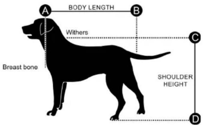
| Trailer Size Medium | |
| Max. Body Length 26 in. (67 cm) | |
| Max. Shoulder Height 19.5 in. (50 cm) | |
| Max. Weight 50 lbs. (23 kg) |
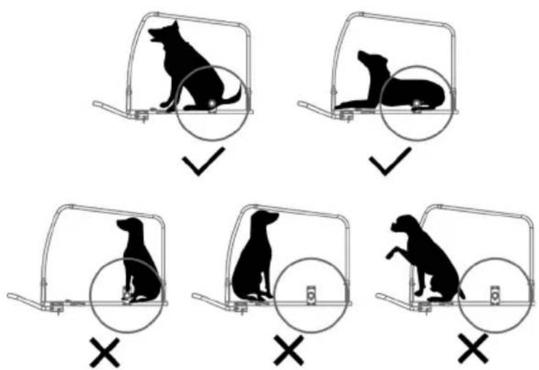
Note: Make sure that your dog is positioned with its center of gravity as close as possible to the wheel axle. This is the best way to ride with an optimal weight distribution.
PARTS IN PACKAGE 10045935, 10045936
natural_image
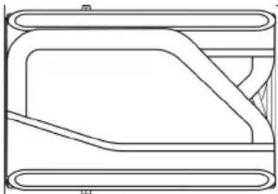
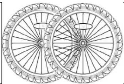
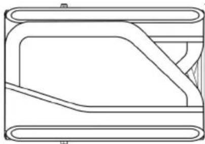
Pure technical line drawing of a mechanical component or bracket (no text or symbols)1 x Main frame 2 x wheels
natural_image
Line drawing of two bicycle wheels with spokes and wheel rim (no text or symbols)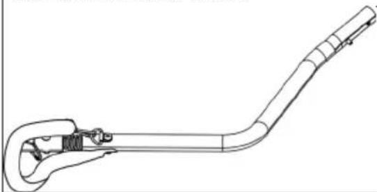
natural_image
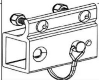
Line drawing of a mechanical tool or device with a curved handle and attached bracket (no text or symbols)1 x tow bar 1 x tow bar receiver
natural_image
Technical line drawing of a mechanical bracket with bolts and a coiled cable (no text or symbols)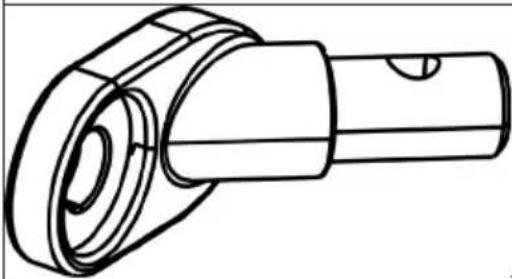
natural_image
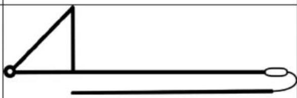
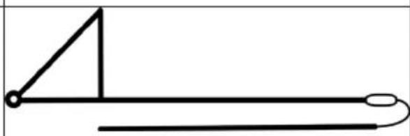
Technical line drawing of a mechanical component with cylindrical and flanged sections (no text or symbols)1 x universal hitch 1 x flag
natural_image
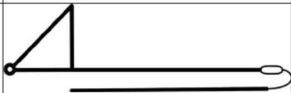
Simple line drawing of a right triangle connected to a horizontal line with a curved base (no text or symbols)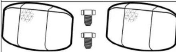
natural_image
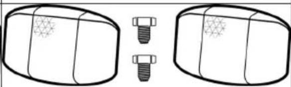
Diagram showing two cylindrical objects with star patterns, each with a separate screw and bolt (no text or symbols)2 x front reflectors (white) 2 x rear reflectors (red)
natural_image
Diagram showing two cylindrical objects with star patterns, each with a separate screw and a separate bolt (no text or symbols)Tools
natural_image
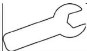
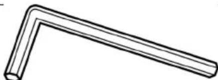
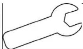
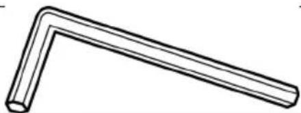
Simple line drawing of a wrench (no text or symbols)11 mm wrench 4 mm hex key
natural_image
Simple line drawing of a bent pipe or angle (no text or symbols)PARTS IN PACKAGE 10045937, 10045938
natural_image
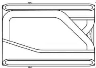
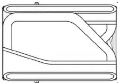
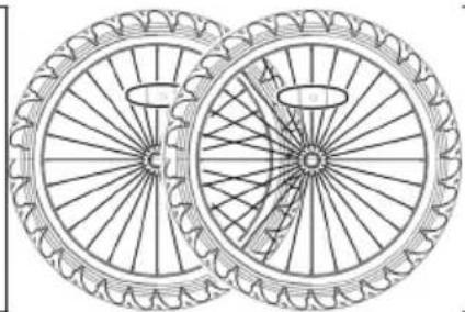
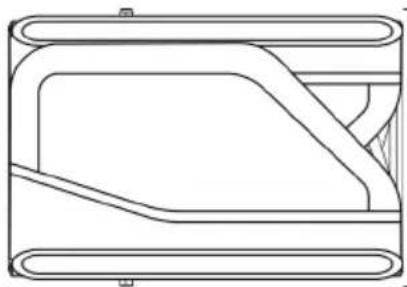
Pure technical line drawing of a mechanical component or bracket (no text or symbols)1 x Main frame 2 x wheels
natural_image
Two bicycle wheel rim designs with spokes and hub, no text or symbols present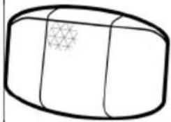
natural_image
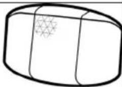
Simple line drawing of a 3D rectangular object with a grid pattern on its surface (no text or symbols)
natural_image
Simple line drawing of a 3D rectangular block with a star-like pattern on its side (no text or symbols)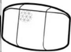
natural_image
Simple line drawing of a cylindrical object with a star-like pattern on its side (no text or symbols)
natural_image
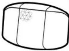
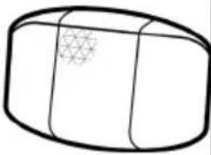
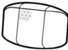
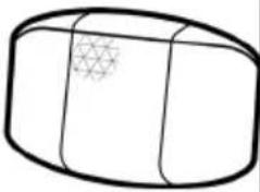
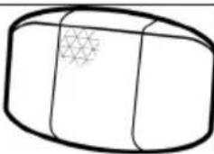
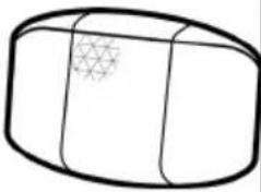
Simple line drawing of a 3D rectangular object with a star-like pattern on its surface (no text or symbols)2 x front reflectors (white) 2 x rear reflectors (red)
natural_image
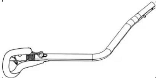
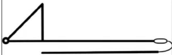
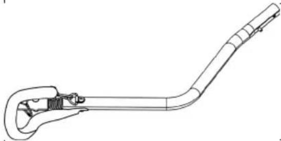
Line drawing of a mechanical tool or device with a curved handle and lever (no text or symbols)1 x tow bar 1 x flag
natural_image
Simple line drawing of a right triangle and a horizontal line with a loop, no text or symbols present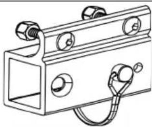
natural_image
Technical line drawing of a mechanical bracket with multiple circular components and a coiled cable (no text or symbols)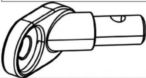
natural_image
Technical line drawing of a mechanical component with cylindrical and flanged sections (no text or symbols)1 x universal hitch 1 x tow bar receiver

natural_image
Simple line drawing of a mechanical component with three ports and a handle (no text or symbols)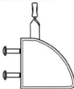
natural_image
Simple line drawing of a three-pin electrical connector (no text or symbols)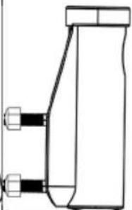
natural_image
Pure technical line drawing of a mechanical component without any text, numbers, or symbols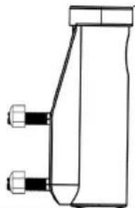
natural_image
Pure technical line drawing of a mechanical component with no text or symbols2 x wheel guard 2 x handle bar holder
natural_image
Technical line drawing of a car wheel assembly with five spokes and a handle (no text or symbols)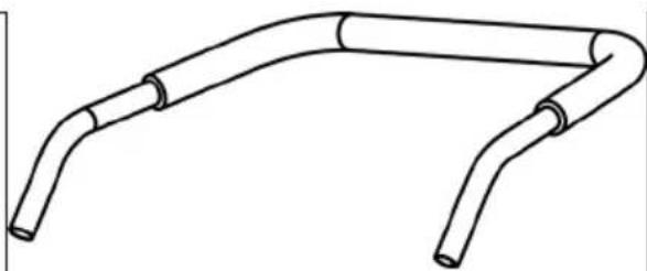
natural_image
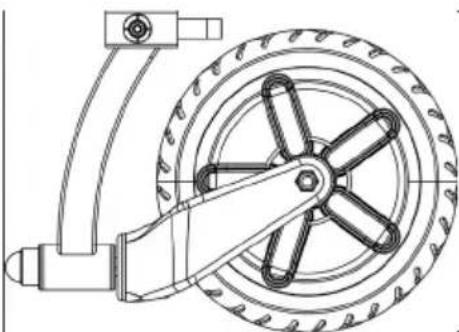
Line drawing of a flexible pipe or conduit with two curved ends (no text or symbols)1 x front wheel with quick release skewer 1 | x handle bar
Tools
natural_image
Simple line drawing of a wrench (no text or symbols)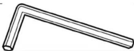
natural_image
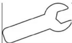
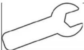
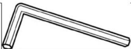
Simple line drawing of a bent pipe or angle (no text or symbols)11 mm wrench 4 mm hex key
ASSEMBLY
1. Opening the main frame
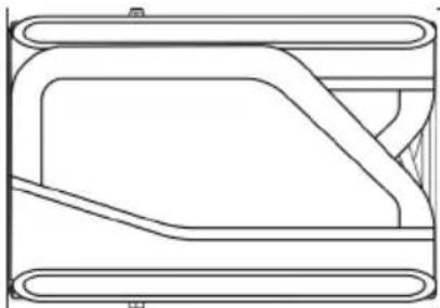
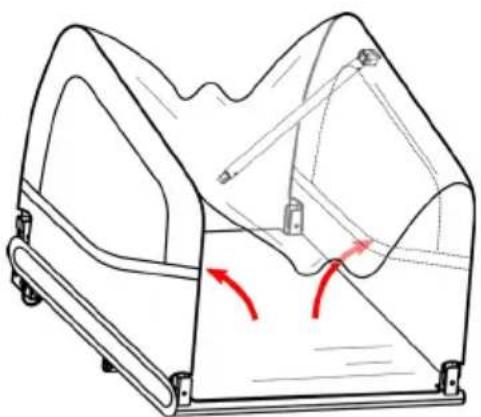
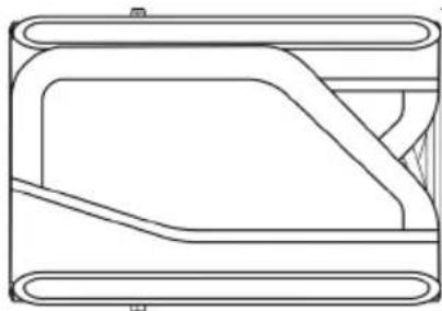
Take out the trailer main frame and all other components from the carton. Remove black protective caps on 4 corners. Raise both side panels to an upright position (Figure 1).
natural_image
Technical line drawing of a mechanical component with red arrows indicating motion or force direction (no text or symbols)Figure 1
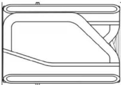
Fasten the crossbar to the top part of the main frame. Raise and lock the cross bar using the safety pin attached to the bolt (Figure 2). Make sure that safety pins are properly locked in place as shown (Figure 3).
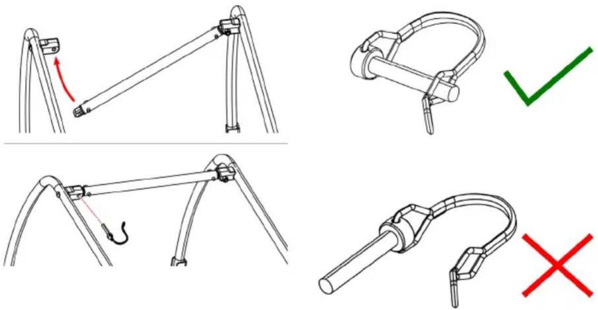
Figure 2 Figure 3
2. Attaching the wheels
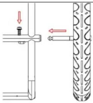
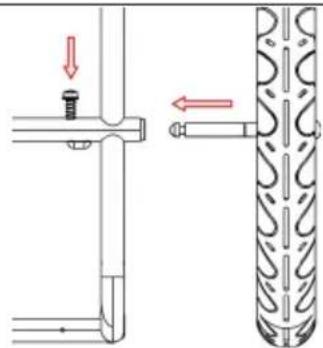
Insert wheel axle into axle receiver underneath the trailer frame until it snaps in place (Figure 4). Pull firmly on wheel to confirm the axle is fully engaged (Figure 5). To remove the wheels, press the button on the axle receiver and take the wheels out.
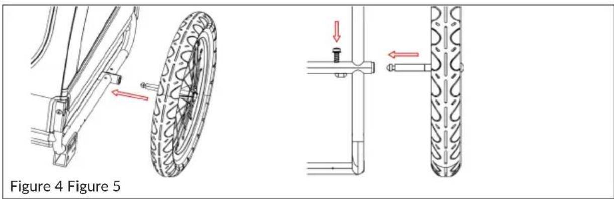
3. Installing the tow bar
Fix the tow bar receiver to main frame as shown (Figure 6)
Pressing the spring button, slide the tow bar into the tow bar receiver until the spring button comes out of the hole A. Insert the safety pin from the hole B through the other side. Make sure the safety pin is properly locked in place.
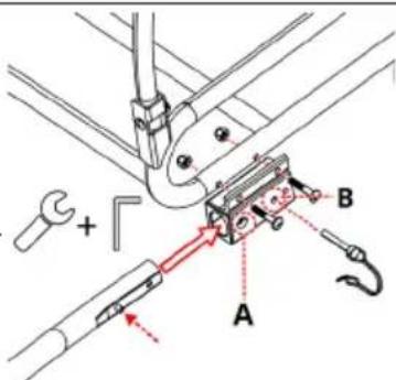
Figure 6
4. Attaching the flag
Insert the flag pole into the flagpole pocket at the left rear corner of the side panel (Figure 7, Figure 8).
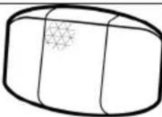
Insert screws into holes on the cover to fasten front (white) and rear (red) reflectors.
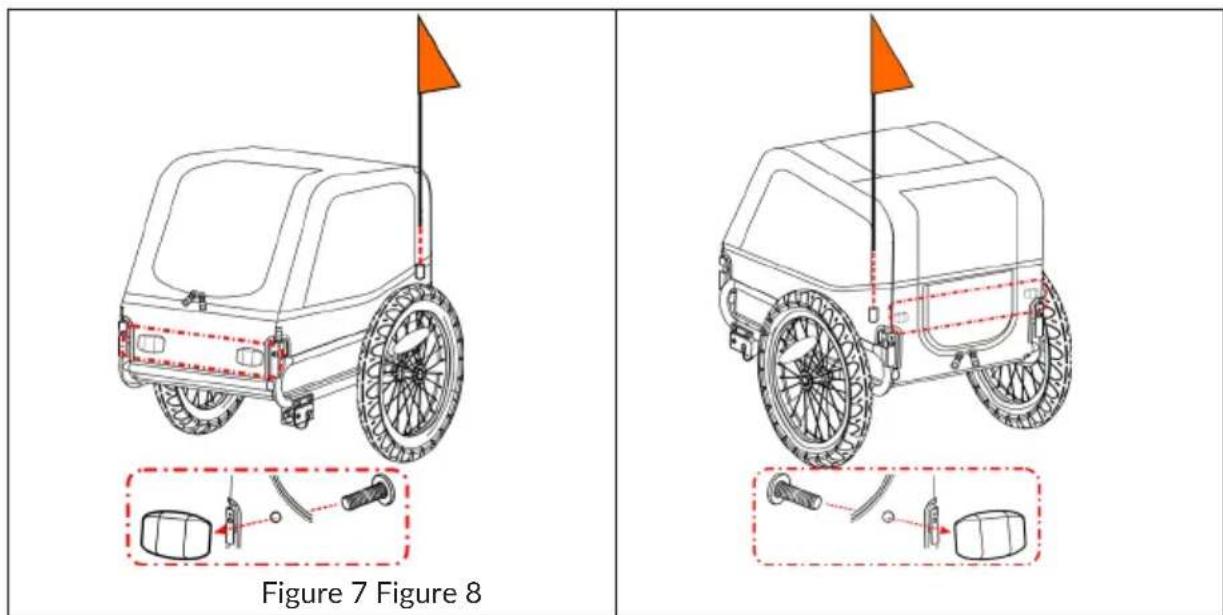
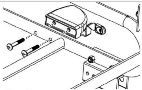
5. Installing the parking brakes/ Wheel guards (10045937 & 10045938)
Insert wheel guard bolts through frame tube. Match holes in wheel guards to bolts. Tighten securely with hex key (Figure 9). Repeat for wheel guard on other side.
natural_image
Technical line drawing of a mechanical assembly with bolts and components (no text or symbols)Figure 9
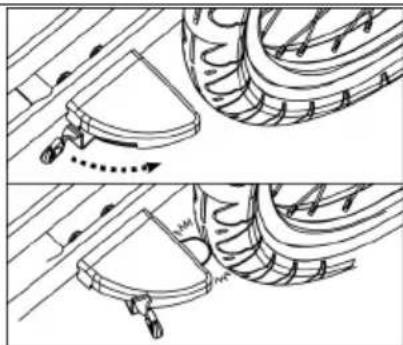
Pull outward the handle on wheel guard to brake. Push back the handle to release (Figure 10).

WARNING
Always engage the brakes when not riding/pushing.
natural_image
Technical line drawing showing two mechanical assembly steps with arrows indicating motion (no text or symbols)Figure 10
Installing the stroller kit (10045937 & 10045938)
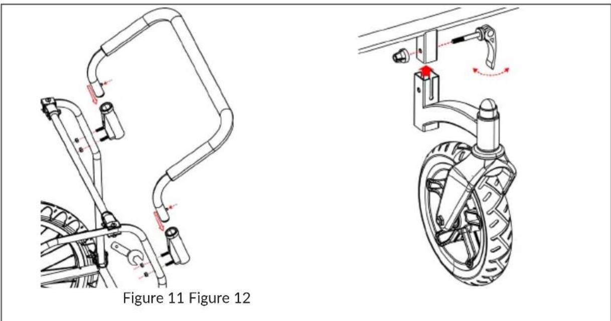
Fix two handle receivers onto the rear tubes of frame by tightening the nuts. On handle ends, press the spring buttons in and slide the handle into handlebar receivers until two spring buttons pop up through the holes (Figure 11). To remove handle, push buttons in and pull up on handle.
Insert the rectangle tube on the front wheel into the rectangle holder underneath the front frame of the trailer. Make sure that holes on both rectangle tubes line up. Lock the front wheel using the quick release skewer (Figure 12).
IMPORTANT: Tow bar must be removed before using the stroller kit.
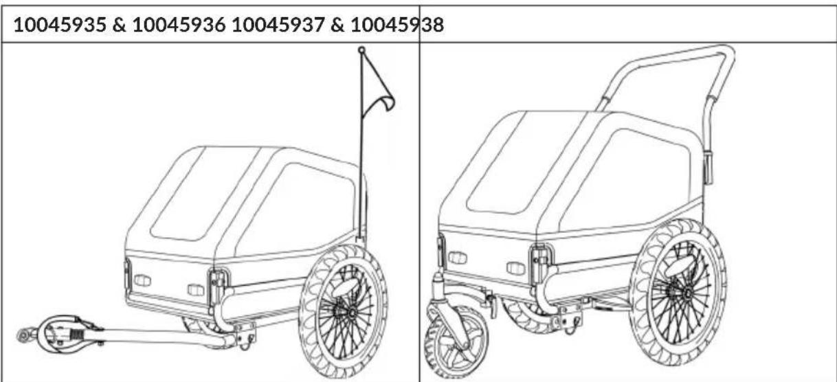
Assembled Trailer
ATTACHING TRAILER TO BICYCLE
1. Quick release Axle
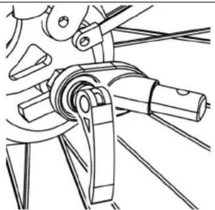
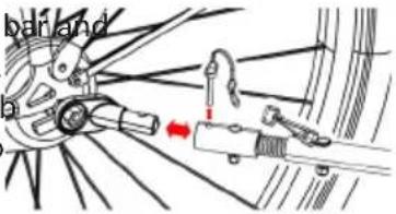
Remove the quick release from the left side of bike's rear axle. Install the hitch between the quick release and frame. Tighten the quick release following the bike manufacturer's manual. Hitch can remain on the bike when the trailer is removed (Figure 13).
natural_image
Technical line drawing of a mechanical assembly with no visible text or symbolsFigure 13
WARNING!
Danger of serious injury or death
- The tension-adjusting nut must engage the threads for at least five full turns in order to ensure adequate clamping force for holding the rear wheel securely.
- Failure to tighten the tension-adjusting nut fully may result in accidents with serious injury or death. If the quick release skewer is too short, it must be replaced.
- Consult a professional bicycle mechanic for the appropriate parts and assistance.
2. Nutted Axle
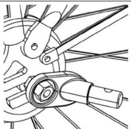
Unscrew the nut with washer from the left side of bike's rear axle. Install the hitch onto the axle and screw the nut back on with the washer (Figure 14).
natural_image
Mechanical linkage diagram showing a chain with joints and links (no text or symbols)Figure 14
WARNING!
Danger of serious injury or death
- The axle nut must engage the threads for at least five full turns in order to ensure adequate clamping force for holding the rear wheel securely.
- Failure to tighten the nut fully may result in accidents with serious injury or death. If the axle is too short, the Universal Hitch cannot be used!
- Consult a professional bicycle mechanic for the appropriate parts and assistance.
3. Thru Axle
The universal hitch doesn't fit a bike with thru axle. Please consult the retailer for possible solution.
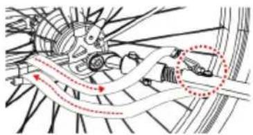
Connect the coupler on the tow secure the safety pin (Figure 15). tow bar is attached, wrap safety in the frame of the bike and hook of D-ring on the tow bar.
natural_image
Mechanical assembly diagram showing gear and shaft components with motion arrows (no text or labels)Figure 15
BEFORE YOU RIDE
Check before each use:
- Wheels are properly secured to the trailer
- Tires are inflated to recommended pressure on the tire side wall
- Tow bar is properly secured to the trailer
- Hitch is properly secured to the bicycle
- All safety pins are securely locked in place.
- Safety strap on the tow bar is properly installed
- Weight of tow bar at coupler is greater than 6.6 lbs. (3 kg) but does not exceed 17.6 lbs. (8 kg) with fully loaded trailer
- Make sure that bicycle is in proper working order, especially brakes and tires (refer to bicycle manufacturer's instructions)
- Safety flag is in place
- Always leash your dog/pet in the trailer.
CARE AND MAINTENANCE
Storage
For longer product life, store trailer indoors. The trailer should not be stored at temperatures less than -10 ^ ( -23 ^ ) or greater than 150 ^ ( 65 ^ ).
Fabric Care
Hand wash fabric parts with warm water and mild soap. DO NOT use bleach or solvents. Wipe dry and store out of direct sunlight in a dry, well-ventilated area. Clean windows with a damp, soft cloth.
Estimado cliente:
ÍNDICE
Berlin Brands Group UK Limited
PO Box 42
272 Kensington High Street
London, W8 6ND
Reino Unido

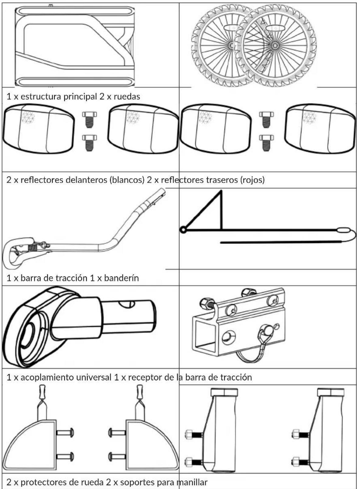
CONTENIDO DEL ENVÍO 10045935, 10045936
natural_image
Pure technical line drawing of a mechanical component or bracket (no text or symbols)natural_image
Two identical bicycle wheel rim diagrams with spokes and wheels, no text or symbols present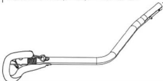
natural_image
Line drawing of a mechanical tool or device with a curved handle and handlehead (no text or symbols)natural_image
Technical line drawing of a mechanical bracket with bolts and tubing (no text or symbols)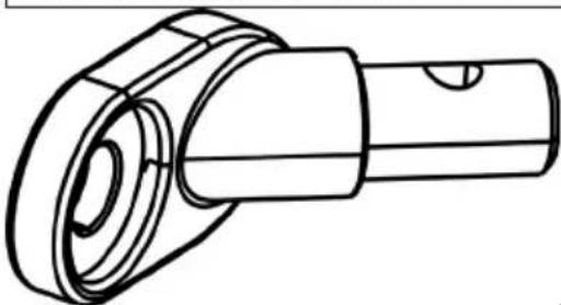
natural_image
Technical line drawing of a mechanical component with cylindrical body and flanged ends (no text or symbols)1 x acoplamiento universal 1 x banderín
natural_image
Simple line drawing of a right triangle and a horizontal line with a curved end (no text or symbols)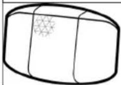
natural_image
Simple line drawing of a cylindrical object with a star-like pattern on its side (no text or symbols)
natural_image
Simple line drawing of a 3D rectangular block with a grid pattern on its side (no text or symbols)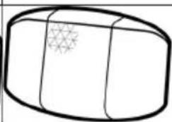
natural_image
Simple line drawing of a cylindrical object with a star-like pattern on its side (no text or symbols)
natural_image
Simple line drawing of a rectangular object with a grid pattern on its surface (no text or symbols)2 x reflectores delanteros (blancos) 2 x reflectores traseros (rojos)
Herramientas
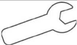 | 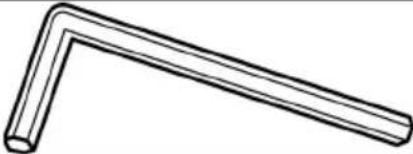 | |||
| Llave inglesa de 11 mm Llave Allen | ||||
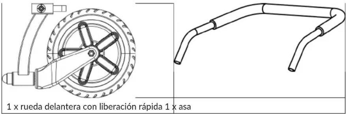
CONTENIDO DEL ENVÍO 10045937, 10045938
natural_image
Technical line drawing of a mechanical component with red arrows indicating motion or movement (no text or symbols)Figura 1
Figura 2 Figura 3
natural_image
Technical diagram showing a bicycle suspension system with a tire and mechanical components (no text or labels)Figura 4 Figura 5
natural_image
Technical diagram showing pipe connection and shear stress application on a cylindrical component (no text or symbols)Figura 6
natural_image
Technical line drawing of a mechanical assembly with rollers and brackets (no text or symbols)Figura 9
natural_image
Technical line drawing showing two mechanical components with motion arrows, no text or symbols presentFigura 10
natural_image
Technical line drawing of a mechanical assembly with pipes and connectors (no text or symbols)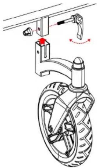
natural_image
Mechanical diagram showing a car wheel assembly with a lever and adjustment mechanism (no text or symbols)Figura 11 Figura 12
natural_image
Technical line drawing of a mechanical assembly with levers and gears (no text or symbols)Figura 13
¡ADVERTENCIA!
natural_image
Mechanical linkage diagram showing interlocking components (no text or symbols)Figura 14

¡ADVERTENCIA!
natural_image
Mechanical assembly diagram showing a motor and gear mechanism (no text or labels)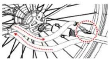
natural_image
Mechanical assembly diagram showing gear and shaft components with motion arrows (no text or labels)ANTES DEL VIAJE
Cher client, chère cliente,
SOMMAIRE
Berlin Brands Group UK Ltd
PO Box 42
272 Kensington High Street
London, W8 6ND
United Kingdom

MISE EN GARDE!
CONTENU DE L'EMBALLAGE 10045935, 10045936
natural_image
Pure technical line drawing of a mechanical component or bracket (no text or symbols)natural_image
Two identical bicycle wheel rim diagrams with spokes and wheels, no text or symbols present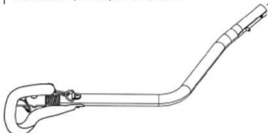
natural_image
Line drawing of a mechanical tool or device with a curved handle and attached bracket (no text or symbols)natural_image
Technical line drawing of a metal bracket with bolts and coiled cable (no text or symbols)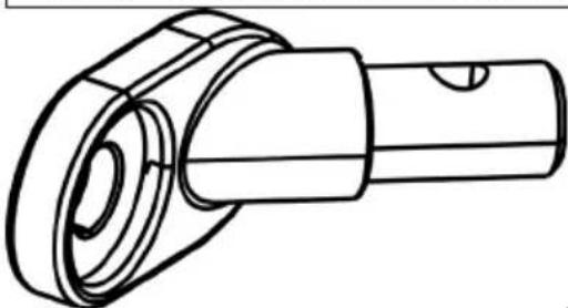
natural_image
Technical line drawing of a mechanical component with no visible text or symbolsnatural_image
Simple line drawing of a right triangle and a horizontal rod with a curved base (no text or symbols)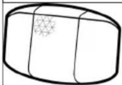
natural_image
Simple line drawing of a 3D rectangular object with a star-like pattern on its side (no text or symbols)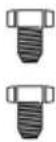
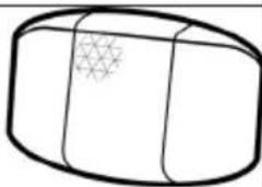
natural_image
Simple line drawing of a rectangular object with a grid pattern on its surface (no text or symbols)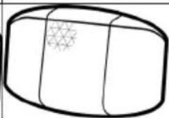
natural_image
Simple line drawing of a cylindrical object with a star-like pattern on its side (no text or symbols)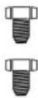
natural_image
Simple line drawing of a rectangular object with a star-like pattern on its side (no text or symbols)natural_image
Technical line drawing of a mechanical component with red arrows indicating motion or force direction (no text or symbols)Figure 1
Figure 2 Figure 3
natural_image
Technical diagram of a bicycle suspension system showing frame, wheel, and bracket components (no text or labels)Figure 4 Figure 5
3. Installation de la barre de traction
Figure 6
natural_image
Technical line drawing of a mechanical assembly with no visible text or symbolsFigure 9
natural_image
Technical line drawing showing two mechanical components with motion arrows, no text or symbols presentFigure 10
natural_image
Technical line drawing of a mechanical assembly with pipes and connectors (no text or symbols)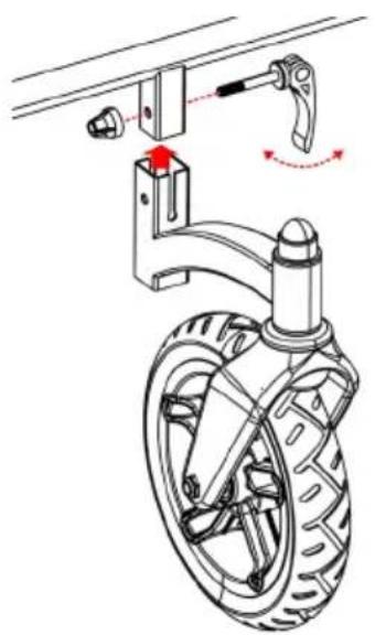
natural_image
Mechanical diagram showing a car wheel assembly with a lever and adjustment mechanism (no text or labels)Figure 11 Figure 12
natural_image
Technical line drawing of a mechanical assembly with levers and gears (no text or symbols)Figure 13
MISE EN GARDE!
natural_image
Mechanical assembly diagram showing linkage mechanism with no visible text or symbolsFigure 14
MISE EN GARDE!
natural_image
Mechanical assembly diagram showing a motor and linkage mechanism (no text or labels)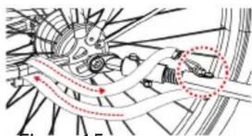
natural_image
Technical diagram of a mechanical assembly with no visible text or symbolsFigure 15
AVANT DE PRENDRE LA ROUTE
INDICE
PRODUTTORE E IMPORTATORE (UK)
Produttore:
Chal-Tec GmbH, Wallstraße 16, 10179 Berlino, Germania.
Berlin Brands Group UK Limited
PO Box 42
272 Kensington High Street
London, W8 6ND
United Kingdom

VOLUME DI CONSEGNA 10045935, 10045936
IT
natural_image
Pure technical line drawing of a mechanical component or bracket (no text or symbols)natural_image
Line drawing of two bicycle wheels with spokes and wheel rim (no text or symbols)
natural_image
Line drawing of a mechanical tool or device with a curved handle and attached bracket (no text or symbols)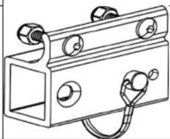
natural_image
Technical line drawing of a metal bracket with multiple circular cutouts and a coiled cable (no text or symbols)natural_image
Technical line drawing of a mechanical component with cylindrical and flanged sections (no text or symbols)natural_image
Simple line drawing of a right triangle and a horizontal line with a loop, no text or symbols present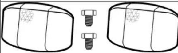
natural_image
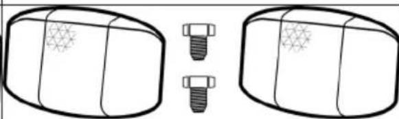
Diagram showing two cylindrical objects with textured surfaces and two separate bolts (no text or symbols)2 x catarifrangenti anteriori (bianchi) 2 x catarifrangenti posteriori (rossi)
natural_image
Diagram showing two cylindrical objects with star patterns, each with a separate screw and a separate nut (no text or symbols)Attrezzi
natural_image
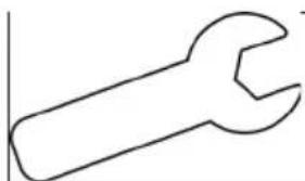
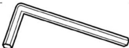
Simple line drawing of a wrench (no text or symbols)Chiave da 11 mm Chiave a brugola
natural_image
Simple line drawing of a bent pipe or angle (no text or symbols)VOLUME DI CONSEGNA 10045937, 10045938
natural_image
Pure technical line drawing of a mechanical component or bracket (no text or symbols)natural_image
Two bicycle wheel rim designs with spokes and hub, no text or symbols present
natural_image
Simple line drawing of a 3D rectangular object with a grid pattern on its surface (no text or symbols)
natural_image
Simple line drawing of a 3D rectangular block with a grid pattern on one side (no text or symbols)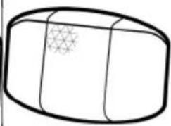
natural_image
Simple line drawing of a cylindrical object with a star pattern on its side (no text or symbols)
natural_image
Simple line drawing of a cylindrical object with a star-like pattern on its surface (no text or symbols)2 x catarifrangenti anteriori (bianchi) 2 x catarifrangenti posteriori (rossi)
natural_image
Line drawing of a handheld tool or device with a curved handle and handle (no text or symbols)natural_image
Simple line drawing of a right triangle and a horizontal line with a loop, no text or symbols present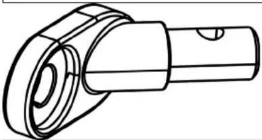
natural_image
Technical line drawing of a mechanical component with no visible text or symbolsnatural_image
Technical line drawing of a mechanical bracket with bolts and a coiled cable (no text or symbols)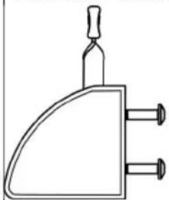
natural_image
Simple line drawing of a mechanical component with three pins and a handle (no text or symbols)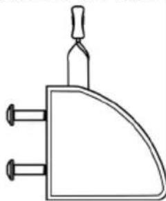
natural_image
Simple line drawing of a three-pin electrical plug (no text or symbols)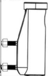
natural_image
Pure technical line drawing of a mechanical component without any text, numbers, or symbols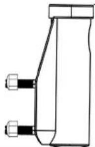
natural_image
Pure technical line drawing of a mechanical component with no text or symbolsnatural_image
Technical line drawing of a car wheel assembly with five spokes and a handle (no text or symbols)natural_image
Simple line drawing of a U-shaped pipe or conduit with two flanged ends (no text or symbols)1 x impugnatura
Attrezzi
natural_image
Simple line drawing of a wrench (no text or symbols)Chiave da 11 mm Chiave a brugola da 4 mm
natural_image
Simple line drawing of a bent pipe or angle (no text or symbols)ASSEMBLAGGIO
natural_image
Technical line drawing of a mechanical assembly with red arrows indicating motion or force direction (no text or symbols)Immagine 1
4. Installare la bandierina
natural_image
Technical line drawing of a mechanical assembly with rollers and a housing (no text or symbols)Immagine 9
natural_image
Technical line drawing showing two mechanical assembly steps with motion arrows (no text or symbols)Immagine 10
natural_image
Technical line drawing of a mechanical assembly with pipes and connectors (no text or symbols)natural_image
Mechanical diagram showing a car wheel assembly with a lever and adjustment mechanism (no text or symbols)natural_image
Technical line drawing of a mechanical assembly with no visible text or symbolsImmagine 13
AVVERTIMENTO!
natural_image
Mechanical linkage diagram showing a chain with joints and links (no text or symbols)Immagine 14
natural_image
Mechanical assembly diagram showing a motor and gear mechanism with no visible text or symbols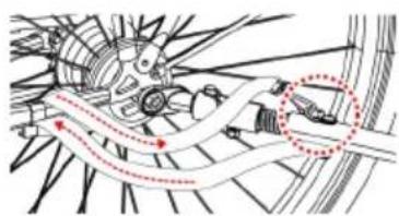
natural_image
Mechanical assembly diagram showing gear and shaft components with motion arrows (no text or labels)Immagine 15
PRIMA DI METTERSI IN VIAGGIO

- INHALTSVERZEICHNIS
- LIEFERUMFANG 10045935, 10045936
- Werkzeuge
- LIEFERUMFANG 10045937, 10045938
- ZUSAMMENBAU
- Attaching the wheels
- WARNUNG!
- VOR DER FAHRT
- CONTENTS
- TECHNICAL DATA
- MANUFACTURER & IMPORTER (UK)
- Manufacturer:
- Importer for Great Britain:
- WARNING!
- Danger of serious injury or death
- PARTS IN PACKAGE 10045935, 10045936
- Tools
- PARTS IN PACKAGE 10045937, 10045938
- ASSEMBLY
- Opening the main frame
- Installing the tow bar
- Attaching the flag
- Installing the parking brakes/ Wheel guards (10045937 & 10045938)
- WARNING
- Installing the stroller kit (10045937 & 10045938)
- Assembled Trailer
- ATTACHING TRAILER TO BICYCLE
- Quick release Axle
- Nutted Axle
- Thru Axle
- BEFORE YOU RIDE
- Check before each use:
- CARE AND MAINTENANCE
- Storage
- Fabric Care
- Estimado cliente:
- ÍNDICE
- CONTENIDO DEL ENVÍO 10045935, 10045936
- Herramientas
- CONTENIDO DEL ENVÍO 10045937, 10045938
- ¡ADVERTENCIA!
- ANTES DEL VIAJE
- Cher client, chère cliente,
- SOMMAIRE
- MISE EN GARDE!
- CONTENU DE L'EMBALLAGE 10045935, 10045936
- Installation de la barre de traction
- AVANT DE PRENDRE LA ROUTE
- INDICE
- PRODUTTORE E IMPORTATORE (UK)
- Produttore:
- VOLUME DI CONSEGNA 10045935, 10045936
- Attrezzi
- VOLUME DI CONSEGNA 10045937, 10045938
- ASSEMBLAGGIO
- Installare la bandierina
- AVVERTIMENTO!
- PRIMA DI METTERSI IN VIAGGIO
Brand : Klarfit
Model : Goldie S
Category : Bike trailer