GKF 18V-25 Professional - Milling machine BOSCH - Free user manual and instructions
Find the device manual for free GKF 18V-25 Professional BOSCH in PDF.

| Product Type | Cordless Router (portable trimmer) |
| Brand | Bosch |
| Model | GKF 18V-25 Professional |
| Voltage | 18 V |
| No-load speed | 10,000 - 30,000 rpm |
| Max. cutter diameter | 1-1/2 in (38.1 mm) |
| Collet | 1/4 in (6.35 mm) |
| Compatible bases | Fixed base (GKF001), offset base (PR004), tilt base (PR005), plunge base (PR011) |
| Lighting | LED work lights |
| Electronic speed control | Yes, dial adjustment (6 positions) |
| Cutting depth | Fine and coarse adjustment (micro-fine wheel, rod, and turret for plunge) |
| Spindle lock | Yes, for bit change |
| Weight (without battery) | Approx. 1.5 kg |
| Operating temperature | -20 to +50 °C |
| Safety | Automatic shutdown on stall, restart protection, insulated gripping surface |
| Maintenance | Regular cleaning of ventilation slots, keeping parts clean and grease-free |
| Repairability | Spare parts available, repair by authorized Bosch service center |
| Included accessories | 1/4 in collet, tightening wrench, fixed base (depending on version) |
Frequently Asked Questions - GKF 18V-25 Professional BOSCH
User questions about GKF 18V-25 Professional BOSCH
0 question about this device. Answer the ones you know or ask your own.
Ask a new question about this device
Download the instructions for your Milling machine in PDF format for free! Find your manual GKF 18V-25 Professional - BOSCH and take your electronic device back in hand. On this page are published all the documents necessary for the use of your device. GKF 18V-25 Professional by BOSCH.
USER MANUAL GKF 18V-25 Professional BOSCH
natural_image
Silhouette of a person reading a book inside a circle (no text or symbols)Operating / Safety Instructions
natural_image
3D rendering of a mechanical device with ventilation grilles and control knobs (no visible text or symbols)
BOSCH
Call Toll Free for Consumer Information & Service Locations
| Safety SymbolsThe definitions below describe the level of severity for each signal word.Please read the manual and pay attention to these symbols. | |
 | This is the safety alert symbol. It is used to alert you to potential personal injury hazards. Obey all safety messages that follow this symbol to avoid possible injury or death. |
 | DANGER indicates a hazardous situation which, if not avoided, will result in death or serious injury. |
 | WARNING indicates a hazardous situation which, if not avoided, could result in death or serious injury. |
 | CAUTION indicates a hazardous situation which, if not avoided, could result in minor or moderate injury. |
Table of Contents
General Power Tool Safety Warnings .... 3
Safety Instructions for Cordless Routers .... 5
Additional Safety Warnings .... 5 Disposal .... 6
Intended Use 7
Symbols....8
Getting to Know Your GKF18V-25 Cordless Palm Router....9
Getting to Know Your Offset Base, Tilt Base, and Plunge Base ..... 11
Specifications 12
Assembly 13
Router Bits 13
Replacing the Collet ..... 14
Fixed Base (GKF001) and Accessories....15
Offset Base (PR004) and Accessories 16
Tilt Base (PR005) 18
Plunge Base (PR011) and Accessories 20
Template Guides for Plunge Base (PR011) (optional accessory) ... 21
Changing the Subbase ..... 23
Centering Pin and Cone (RA1151) (optional accessory) ..... 23
Inserting and Removing the Battery Pack .... 24
Adjusting the Clamping Lever ..... 25
Transportation 25
Operation 26
Setting Depth of Cut 26
Operating the Palm Router ..... 29
Feeding the Palm Router ..... 30
Using the Palm Router with Fixed Base (GKF001) and Accessories .... 31
Using the Palm Router with Offset Base (PR004) 33
Using the Palm Router with Tilt Base (PR005) 35
Using the Palm Router with Plunge Base (PR011) and Accessories 36
Maintenance 37
General maintenance ..... 37
Service 37
Cleaning. 37
Storage and Maintenance ..... 37
Repairs. 37
Accessories 38
Troubleshooting....39
General Power Tool Safety Warnings
WARNING
Read all safety warnings, instructions, illustrations and specifications provided with this power tool. Failure to follow all instructions listed
below may result in electric shock, fire and/or serious injury.
SAVE ALL WARNINGS AND INSTRUCTIONS FOR FUTURE REFERENCE.
The term "power tool" in the warnings refers to your mains-operated (corded) power tool or battery-operated (cordless) power tool.
1. Work area safety
a. Keep work area clean and well lit. Cluttered or dark areas invite accidents.
b. Do not operate power tools in explosive atmospheres, such as in the presence of flammable liquids, gases or dust. Power tools create sparks which may ignite the dust or fumes.
c. Keep children and bystanders away while operating a power tool. Distractions can cause you to lose control.
2. Electrical safety
a. Power tool plugs must match the outlet. Never modify the plug in any way. Do not use any adapter plugs with earthed (grounded) power tools. Unmodified plugs and matching outlets will reduce risk of electric shock.
b. Avoid body contact with earthed or grounded surfaces, such as pipes, radiators, ranges and refrigerators. There is an increased risk of electric shock if your body is earthed or grounded.
c. Do not expose power tools to rain or wet conditions. Water entering a power tool will increase the risk of electric shock.
d. Do not abuse the cord. Never use the cord for carrying, pulling or unplugging the power tool. Keep cord away from heat, oil, sharp edges or moving parts. Damaged or entangled cords increase the risk of electric shock.
e. When operating a power tool outdoors, use an extension cord suitable for outdoor use. Use of a cord suitable for outdoor use reduces the risk of electric shock.
f. If operating a power tool in a damp location is unavoidable, use a Ground
Fault Circuit Interrupter (GFCI) protected supply. Use of a GFCI reduces the risk of electric shock.
3. Personal safety
a. Stay alert, watch what you are doing and use common sense when operating a power tool. Do not use a power tool while you are tired or under the influence of drugs, alcohol or medication.
A moment of inattention while operating power tools may result in serious personal injury.
b. Use personal protective equipment. Always wear eye protection. Protective equipment such as a dust mask, non-skid safety shoes, hard hati or hearing protection used for appropriate conditions will reduce personal injuries.
c. Prevent unintentional starting. Ensure the switch is in the off-position before connecting to power source and/or battery pack, picking up or carrying the tool. Carrying power tools with your finger on the switch or energizing power tools that have the switch on invites accidents.
d. Remove any adjusting key or wrench before turning the power tool on. A wrench or a key left attached to a rotating part of the power tool may result in personal injury.
e. Do not overreach. Keep proper footing and balance at all times. This enables better control of the power tool in unexpected situations.
f. Dress properly. Do not wear loose clothing or jewelry. Keep your hair and clothing away from moving parts. Loose clothes, jewelry or long hair can be caught in moving parts.
g. If devices are provided for the connection of dust extraction and collection
General Power Tool Safety Warnings
facilities, ensure these are connected and properly used. Use of dust collection can reduce dust-related hazards.
h. Do not let familiarity gained from frequent use of tools allow you to become complacent and ignore tool safety principles. A careless action can cause severe injury within a fraction of a second.
4. Power tool use and care
a. Do not force the power tool. Use the correct power tool for your application. The correct power tool will do the job better and safer at the rate for which it was designed.
b. Do not use the power tool if the switch does not turn it on and off. Any power tool that cannot be controlled with the switch is dangerous and must be repaired.
c. Disconnect the plug from the power source and/or remove the battery pack, if detachable, from the power tool before making any adjustments, changing accessories, or storing power tools. Such preventive safety measures reduce the risk of starting the power tool accidentally.
d. Store idle power tools out of the reach of children and do not allow persons unfamiliar with the power tool or these instructions to operate the power tool. Power tools are dangerous in the hands of untrained users.
e. Maintain power tools and accessories. Check for misalignment or binding of moving parts, breakage of parts and any other condition that may affect the power tool's operation. If damaged, have the power tool repaired before use. Many accidents are caused by poorly maintained power tools.
f. Keep cutting tools sharp and clean. Properly maintained cutting tools with sharp cutting edges are less likely to bind and are easier to control.
g. Use the power tool, accessories and tool bits etc. in accordance with these instructions, taking into account the working conditions and the work to be
performed. Use of the power tool for operations different from those intended could result in a hazardous situation.
h. Keep handles and grasping surfaces dry, clean and free from oil and grease. Slippery handles and grasping surfaces do not allow for safe handling and control of the tool in unexpected situations.
5. Battery tool use and care
a. Recharge only with the charger specified by the manufacturer. A charger that is suitable for one type of battery pack may create a risk of fire when used with another battery pack.
b. Use power tools only with specifically designated battery packs. Use of any other battery packs may create a risk of injury and fire.
c. When battery pack is not in use, keep it away from other metal objects, like paper clips, coins, keys, nails, screws or other small metal objects, that can make a connection from one terminal to another. Shorting the battery terminals together may cause burns or a fire.
d. Under abusive conditions, liquid may be ejected from the battery; avoid contact. If contact accidentally occurs, flush with water. If liquid contacts eyes, additionally seek medical help. Liquid ejected from the battery may cause irritation or burns.
e. Do not use a battery pack or tool that is damaged or modified. Damaged or modified batteries may exhibit unpredictable behavior resulting in fire, explosion or risk of injury.
f. Do not expose a battery pack or tool to fire or excessive temperature. Exposure to fire or temperature above 265°F (130°C) may cause explosion.
g. Follow all charging instructions and do not charge the battery pack or tool outside the temperature range specified in the instructions. Charging improperly or at temperatures outside the specified range may damage the battery and increase the risk of fire.
General Power Tool Safety Warnings
6. Service
a. Have your power tool serviced by a qualified repair person using only identical replacement parts. This will
ensure that the safety of the power tool is maintained.
b. Never service damaged battery packs. Service of battery packs should only be performed by the manufacturer or authorized service providers.
Safety Instructions for Cordless Routers
Use clamps or another practical way to secure and support the workpiece to a stable platform. Holding the work by your hand or
against the body leaves it unstable and may lead to loss of control.
Additional Safety Warnings
If cutting into existing walls or other blind areas where electrical wiring may exist is unavoidable, disconnect all fuses or circuit breakers feeding this worksite.
Always make sure the work surface is free from nails and other foreign objects. Cutting into a nail can cause the bit and the tool to jump and damage the bit.
Never hold the workpiece in one hand and the tool in the other hand when in use.
Never place hands near or below cutting surface. Clamping the material and guiding the tool with both hands is safer.
Never lay workpiece on top of hard surfaces, like concrete, stone, etc. Protruding cutting bit may cause tool to jump.
Always wear safety goggles and dust mask. Use only in well ventilated area. Using personal safety devices and working in safe environment reduces risk of injury.
After changing the bits or making any adjustments, make sure the collet nut and any other adjustment devices are securely tightened. Loose adjustment device can unexpectedly shift, causing loss of control, loose rotating components will be violently thrown.
Never start the tool when the bit is engaged in the material. The bit cutting edge may grab the material causing loss of control of the cutter.
The direction of feeding the bit into the material is very important and it relates to the direction of bit rotation. When viewing the tool from the top, the bit rotates clockwise. Feed direction of cutting must be counter-clockwise.
NOTE: Inside and outside cuts will require different feed direction, refer to section on feeding the router. Feeding the tool in the wrong direction, causes the cutting edge of the bit to climb out of the work and pull the tool in the direction of this feed.
Never use dull or damaged bits. Sharp bits must be handled with care. Damaged bits can snap during use. Dull bits require more force to push the tool, possibly causing the bit to break.
Never touch the bit during or immediately after the use. After use the bit is too hot to be touched by bare hands.
Never lay the tool down until the motor has come to a complete standstill. The spinning bit can grab the surface and pull the tool out of your control.
Do not use Cutter diameter larger than 1-1/2". Using cutter larger than 1-1/2" may result in personal injury.
Use only router bits that have shank diameters that match the installed collet. Using a router bit that has a smaller shank could
Additional Safety Warnings
cause the bit to come loose during operation and become a projectile.
Never operate router bits at speeds that are higher than their maximum rated speed. Router bits running faster than their rated speed can break and fly apart.
GFCI and personal protection devices like electrician's rubber gloves and footwear will further enhance your personal safety.
Keep handles dry, clean and free from oil and grease. Slippery hands cannot safely control the power tool.
Develop a periodic maintenance schedule for your tool. When cleaning a tool be careful not to disassemble any portion of the tool since internal wires may be misplaced or pinched or safety guard return springs may be improperly mounted. Certain cleaning agents such as gasoline, carbon tetrachloride, ammonia, etc. may damage plastic parts.
WARNING Some dust created by power sanding, sawing, grinding, drilling, and other construction activities contains chemicals known to cause cancer, birth defects or other reproductive harm. Some examples of these chemicals are:
- Lead from lead-based paints,
- Crystalline silica from bricks and cement and other masonry products, and
- Arsenic and chromium from chemically-treated lumber.
Your risk from these exposures varies, depending on how often you do this type of work. To reduce your exposure to these chemicals: work in a well ventilated area, and work with approved safety equipment, such as those dust masks that are specially designed to filter out microscopic particles.
Disposal
This section is part of Robert Bosch Tool Corporation's commitment to preserving our environment and conserving our natural resources.
Tool Disposal
Do not dispose of power tools and batteries/rechargeable batteries into household waste!
Battery Disposal
⚠ WARNING Do not attempt to disassemble the battery or remove any components projecting from the battery terminals. Fire or injury may result. Prior to disposal, protect exposed terminals with heavy insulating tape to prevent shorting.
Lithium-Ion Batteries
If equipped with a lithium-ion battery, the battery must be collected, recycled, or disposed of in an environmentally sound manner.

The EPA certified RBRC Battery Recycling Seal on the lithium-ion (Li-ion) battery indicates Robert Bosch Tool Corporation is voluntarily participating in an industry
program to collect and recycle these batteries at the end of their useful life, when taken out of service in the United States or Canada. The RBRC program provides a convenient alternative to placing used Li-ion batteries into the trash or the municipal waste stream, which may be illegal in your area.
Please call 1-800-8-BATTERY for information on Li-ion battery recycling and disposal bans/restrictions in your area or return your batteries to a Bosch/Dremel Service Center for recycling. Robert Bosch Tool Corporation's involvement in this program is part of our commitment to preserving our environment and conserving our natural resources.
Intended Use
WARNING
Use this palm router only as intended. Unin-
tended use may result in personal injury and property damage.
The power tool is intended for copy routing as well as routing grooves, edges, profiles and elongated holes in wood, plastic and light building materials while resting firmly on the workpiece.
Symbols
Important: Some of the following symbols may be used on your tool. Please study them and learn their meaning. Proper interpretation of these symbols will allow you to operate the tool better and safer.
| Symbol Designation/Explanation | |
| V Volts (voltage) | |
| lb Pounds (weight) | |
| kg Kilograms (weight) | |
| ft Feet (length) | |
| in Inches (length) | |
| m Meter (weight) | |
| cm Centimeter (weight) | |
| mm Minutes (time) | |
| F Fahrenheit (temperature) | |
| C Celsius (temperature) | |
 | Arrow (action in the direction of arrow) |
| - - - - | Direct current (type or a characteristic of current) |
 | This symbol designates that this tool is listed by the Canadian Standards Association, to United States and Canadian Standards. |
 | Designates Li-ion battery recycling program. |
 | Alerts user to read manual. |
 | Alerts user to wear eye protection. |
 | Alerts user to wear hearing protection. |
 | Alerts user to wear respiratory protection. |
 | Alerts user to use eye, hearing, and respiratory protection. |
Fig. 1
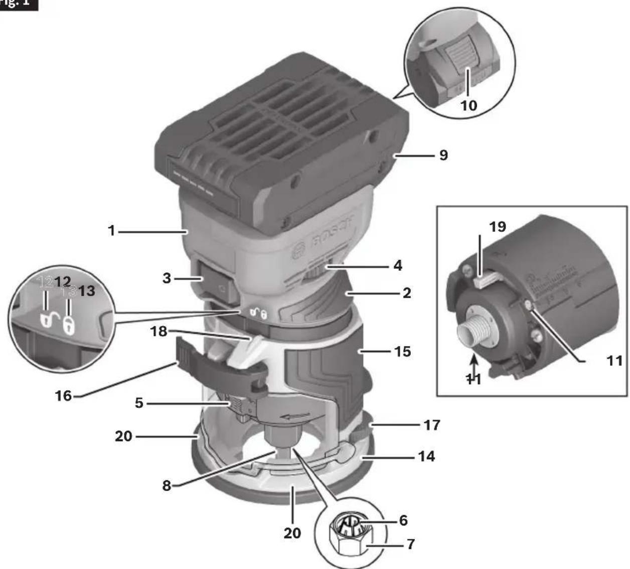
1 Palm Router
2 Palm Router Grip Area (insulated)
3 On/Off Switch
4 Variable Speed Dial
5 Depth Scale (Imperial and Metric)
6 Collet (PR114)
7 Collet Nut (PR114)
8 Spindle
9 Battery Pack
10 Battery Pack Release Button
11 LED Work Lights
12 Unlock Symbol (rough depth adjustment setting)
13 Lock Symbol (fine depth adjustment setting)
14 Fixed Base (GKF001)
15 Fixed Base Grip Area (insulated)
16 Clamping Lever
17 Microfine Adjustment Wheel
18 Depth Setting Indicator
19 Spindle Lock Lever
20 Finger Support Pockets
Fig. 2
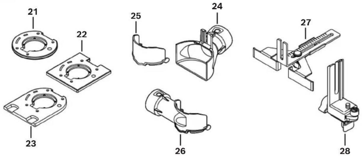
21 Subbase (GKFRD01)
22 Subbase (GKFSQ01)
23 Subbase (GKFD01)
24 Fixed Base Edge Routing Dust Extraction Hood (RA1132)
25 Fixed Base Chip Protection Guard (RA1130)
26 Fixed Base Surface Routing Dust Extraction Hood (RA1131)
27 Straight Edge Guide (PR102)
28 Fixed Base Roller/Bushing Guide (PR003)
Getting to Know Your Offset Base, Tilt Base, and Plunge Base
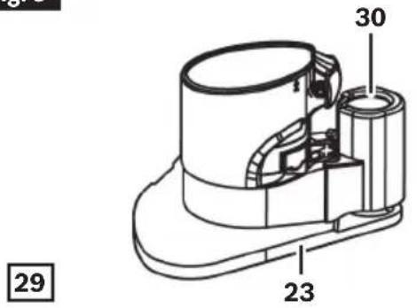
Fig. 3
natural_image
Technical line drawing of a mechanical assembly with rods and brackets (no text or symbols)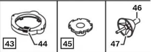
29 Offset Base (PR004)
30 Spindle Lock Button
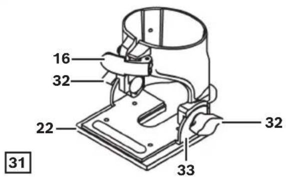
31 Tilt Base (PR005)
32 Wing Screws
33 Angle Scale
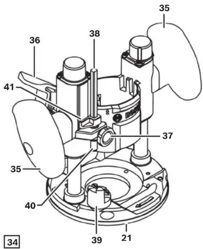
34 Plunge Base (PR011)
35 Plunge Base Grips (insulated)
36 Plunge Lock Lever
37 Thumb Screw
38 Depth Rod
39 Depth Stop Turret
40 Fine Adjustment Knob
41 Depth Indicator
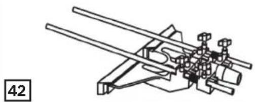
42 Deluxe Router Guide (RA1054)
43 Template Guide Adapter (RA1126)
44 Template Guide Release Lever
45 Template Guide (RA1128)
46 Centering Pin (RA1151)
47 Cone (RA1151)
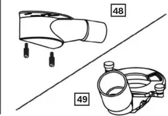
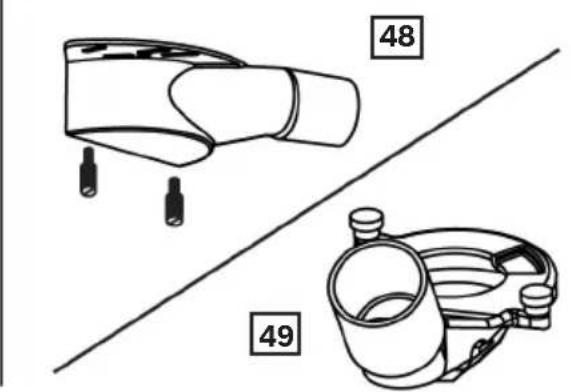
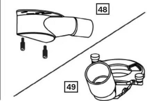
48 Plunge Base Edge Forming Dust Extraction Hood (RA1175)
49 Plunge Base Groove Routing Dust Extraction Hood (PR012)
Specifications
| Model number GKF18V-25 | |
| Voltage 18V | --- |
| No load speed 10,000 - 30,000 RPM | |
| Max bit size 1-1/2 in | |
| Collet size 1/4 in | |
| Permitted battery temperature during charging +32...+11 | 3°F (0...+45°C) |
| Permitted ambient battery temperature during charging | +32...+95°F (0...+35°C) |
| Permitted ambient temperature during operation* and storage | -4...+122°F (-20...+50°C) |
* Performance is limited at temperatures below +32°F (0°C).
Battery Packs/Chargers
Please refer to the battery/charger list included with your tool.
Assembly
WARNING
Disconnect battery pack from tool before assembly, adjustments, troubleshooting or changing accessories. Such preventive safety measures
reduce the risk of starting the tool accidentally, which may result in personal injury.
Router Bits
WARNING
Use only router bits that have shank diameters
that match the installed collet. Using a router bit that has a smaller shank could cause the bit to come loose during operation and become a projectile.
WARNING
Never operate router bits at speeds that are
higher than their maximum rated speed. Router bits running faster than their rated speed can break and fly apart.
Selecting Router Bits
This tool is designed for a wide variety of routing applications that use 1/4" shank bits. These include woodworking applications such as edge forming, grooving, and sign making. This router is also ideal for trimming laminates, phenolics, and other materials that have been bonded to a substrate typically with an overhang of the substrate by about 1/8 in (3 mm). A wide assortment of router bits with different profiles are available as accessories. Only use good quality bits.
Note: Though the router bit may be installed and removed from the palm router while it is installed in a base, it is recommend that the palm router is removed from the base before installing a bit. See the corresponding section for the selected base in use on how to separate the palm router from the base.
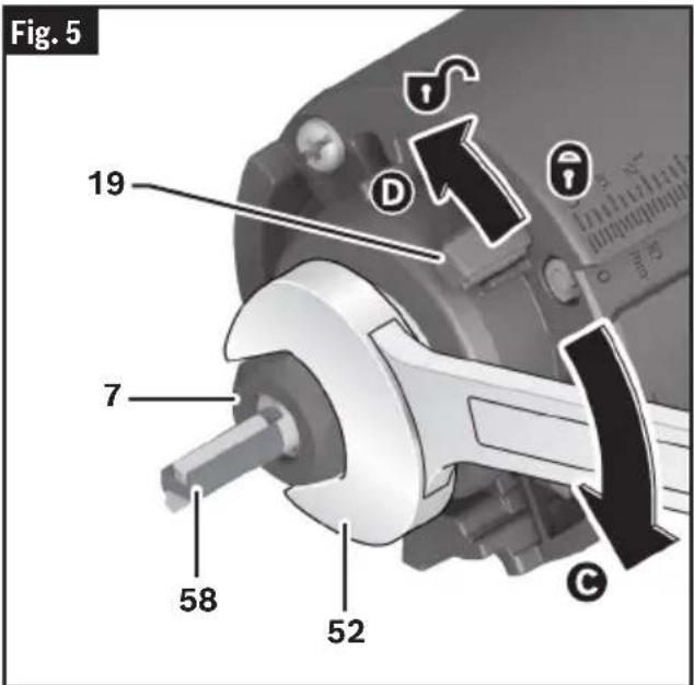
Installing/Removing a Router Bit
(Fig. 4, Fig. 5)
WARNING
Do not use Cutter diameter larger than 1-1/2".
Using cutter larger than 1-1/2" may result in personal injury.
CAUTION
Do not tighten collet without a bit. Tightening collet
without a bit inserted may cause damage to the tool.
Before attaching selected Router Bit 58, ensure that the spindle, collet, collet nut, and bit shank are clean. The bit shank must be straight, undamaged, and an appropriate size in relation to the collet.
- Slide the Spindle Lock Lever 19 to the locked position A to prevent rotation of Collet Nut 7.
Note: It may be necessary to rotate the Collet Nut 7 to engage spindle lock.
-
Use the Collet Nut Wrench 52 to loosen the Collet Nut 7 in a counter-clockwise direction B
-
If necessary, remove the installed router bit.
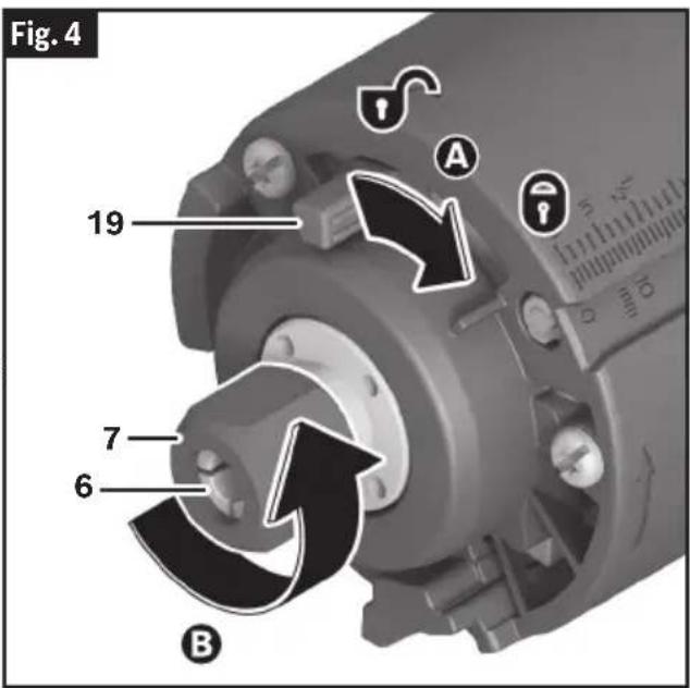
- Insert the shank of the router bit into the Collet 6 as far as it will go, then back the shank out until the cutters are approximately 1/8" to 1/4" away from the collet nut face.
- With the router bit inserted and the spindle lock engaged, use the Collet Nut Wrench 52 to firmly tighten the Collet Nut 7 in a clockwise direction ©
- Slide the Spindle Lock Lever 19 to the unlock position D
Note: To ensure proper gripping of the router bit and minimize run-out, the shank of the router bit must be inserted at least 5/8".
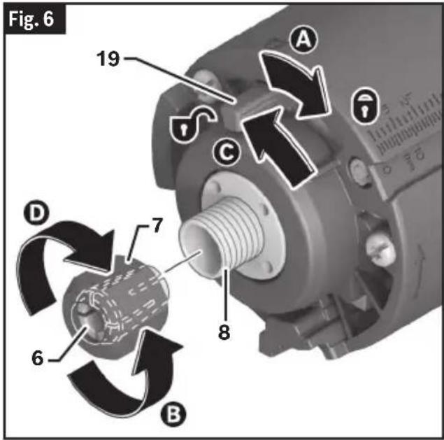
Replacing the Collet
(Fig. 6)
This tool includes a pre-installed 1/4" collet, within the collet nut, that must be used with a 1/4" diameter accessory shank.
To replace the collet assembly:
- Slide the Spindle Lock Lever 19 to the locked position A to prevent rotation of Collet Nut 7.
Note: It may be necessary to rotate the collet nut to engage spindle lock.
- Use the Collet Nut Wrench 52 to loosen the Collet Nut 7 in a counter-clockwise direction B
- Unscrew and remove the collet nut assembly.
- Ensure that the Spindle 8 threads are clean and the Collet 6 is properly fitted in the Collet Nut 7.
- By hand, screw the new collet assembly onto the Spindle 8.
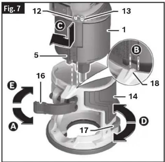
Fixed Base (GKF001) and Accessories
Installing the Palm Router to the Fixed Base
(Fig. 7)
- Open the Clamping Lever 16A
- Align the slot on the Palm Router 1 to the Depth Setting Indicator 18 on the Fixed Base 14 B
- Slide the Palm Router 1 into the Fixed Base 14. The Unlock Symbol 12 indicates you are in the rough depth adjustment setting. Move the Palm Router 1 up or down until the approximate cutting depth is reached on the Depth Scale 5. Rotate the Palm Router 1 clockwise until it locks into the Fixed Base 14; the Depth Setting Indicator 18 will align with the Lock Symbol 13 on the router. The Lock Symbol 13 indicates you are in the fine depth adjustment setting.
- Use the Microfine Adjustment Wheel 17 to precisely reach the desired fine depth on the Depth Scale 5 (unavailable for Offset Base PR004).
- Close the Clamping Lever 16E
Note: The tightness of the clamping lever can be adjusted as needed, see section "Adjusting the Clamping Lever" on page 25.
Removing the Palm Router from the Fixed Base
- Open the Clamping Lever 16 then reverse steps 1-3 in "Installing the Palm Router to the Fixed Base" on page 15.
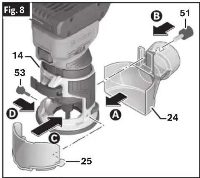
Extraction Hood and Chip Protection Guide (optional accessories)
(Fig. 8)
- Attach the Fixed Base Edge Routing Dust Extraction Hood 24 to the back of the Fixed Base 14
- Secure Fixed Base Edge Routing Dust Extraction Hood 24 in place using the Rear Accessory Thumb Screw 51 B
- Place the Fixed Base Chip Protection Guard 25 over the Fixed Base 14 opening so that the pin on the right side snaps into the hole on the base ©
- Secure the guard in place, on the left side of the base, with the Dust Extraction Thumb Screw 53
- Connect the hood to the vacuum using either a friction fit nozzle or the Bosch quick click system.
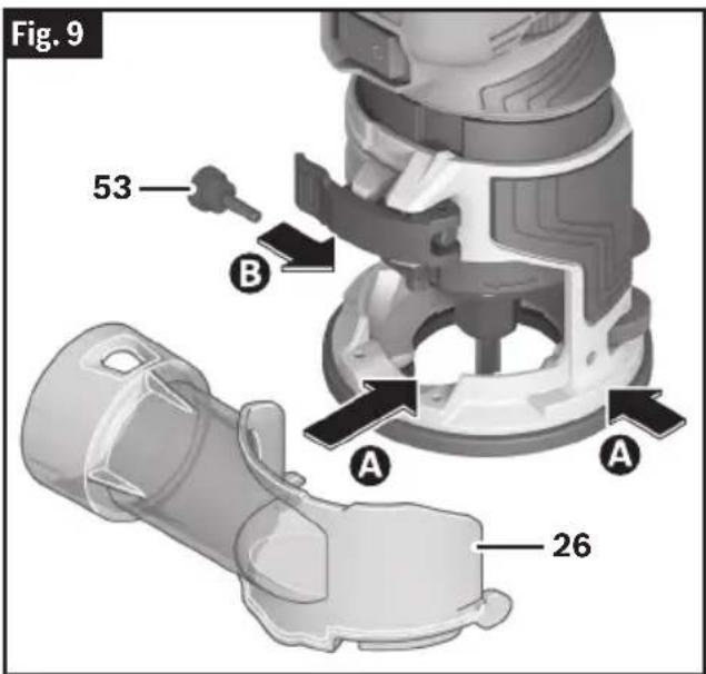
Installing Fixed Base Surface Routing Dust Extraction Hood (optional accessory)
(Fig. 9)
- Place the Fixed Base Surface Routing Dust Extraction Hood 26 over the base opening so that the pin on the right side snaps into the hole on the base A
- Secure the hood in place, on the left side of the base, with the Dust Extraction Thumb Screw 53 B
- Connect the hood to the vacuum using either a friction fit nozzle or the Bosch quick click system.
Offset Base (PR004) and Accessories
The offset base allows routing extremely close to vertical surface in front of the tool; as close as 1/2" when 3/4" bit is used (Removal of the black offset spindle cover further reduces distance from 3/4" bit and vertical surface to 3/8".) The 1-1/16" base opening makes it possible to use bits that have cutters as wide 13/16".
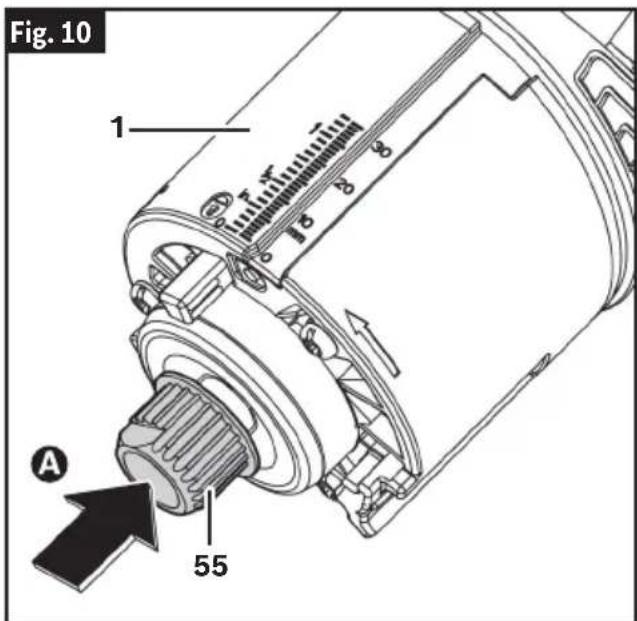
Installing the Palm Router to the Offset Base
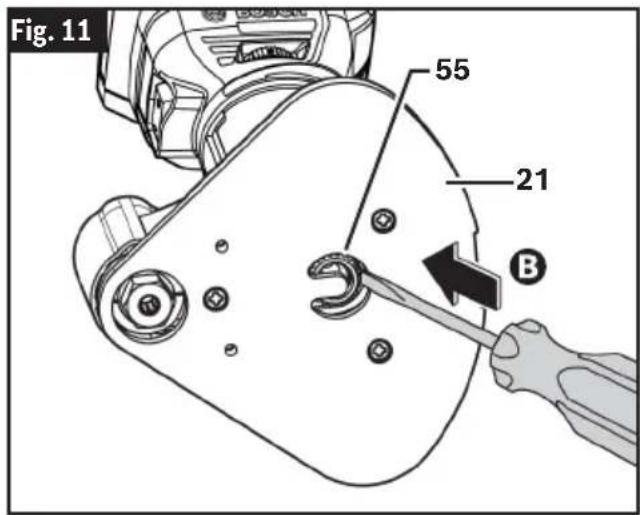
(Fig. 10, Fig. 11)
- Remove the Collet 6 and Collet Nut 7 from motor and install Drive Gear 55 using Collet Nut Wrench 52. See "Replacing the Collet" on page 14. Make sure that Drive Gear 55 is fully tightened onto the palm router's Spindle 8 A
- Install the Palm Router 8 into the Offset Base 29. See section "Installing the Palm Router to the Tilt Base" on page 18.
Note: Fine depth adjustment not available for Offset Base.
- Insert a screwdriver through the U-shaped opening in the Subbase 21 to fit belt over Drive Gear 55 B
Assembly
Removing the Palm Router from the Offset Base
- Open the Clamping Lever 16 then reverse steps 1-4 from section "Installing the Palm Router to the Tilt Base" on page 18.
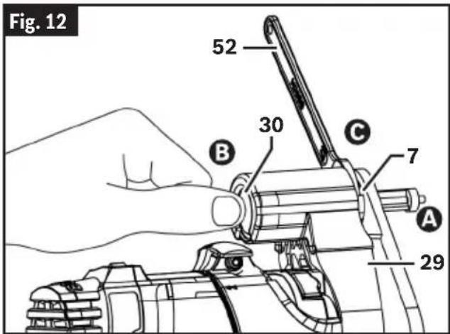
Installing the Bit to the Offset Base (Fig. 12)
- Insert the shank of the router bit into the Collet 6 on the Offset Base 29 as far as it will go, then back the shank out until the cutters are approximately 1/8" to 1/4" away from the collet nut face
- Press the Spindle Lock Button 30 on top of offset spindle B
- Tighten Collet Nut 7 using the Collet Nut Wrench 52 ©
Note: The collet used on the PR004 is the same type of self-releasing collet used on the palm router itself when used with the Fixed Base 14.
- Make a trial cut to check the depth and readjust as necessary. See "Using the Palm Router with Offset Base (PR004)" on page 33.
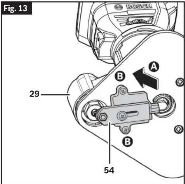
Attaching the Offset Base Roller/ Bushing Guide
(Fig. 13)
The offset base roller/bushing guide is required when edge-forming or trimming with unpiloted non-bearing bits.
- Position the Offset Base Roller/Bushing Guide 54 to the bottom of the Offset Base 29 A and secure it in place using the two provided screws B
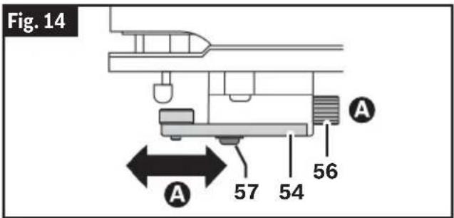
Whether making straight or bevel cuts, the width of material removed is determined by the distance between the front of the router bit's cutter and the front of the roller/bushing.
Adjust the front of the roller/bushing as follows:
- Using a screwdriver, loosen the Clamping Screw 57 underneath the Offset Base Roller/Bushing Guide 54.
- Rotate the Knurled Knob 56 to move the roller/bushing in or out to create the amount of cutter exposure needed to trim the workpiece flush with the guiding surface or to create the desired bevel A
- Be sure the bit clears the top of the Offset Base Roller/Bushing Guide 54 by at least 1/8" (3 mm) to avoid damage.
- Retighten the Clamping Screw 57.
- Make a trial cut to check the setting and readjust as necessary, see section "Offset Base Roller/Bushing Guide (optional accessory)" on page 34.
Tilt Base (PR005)
The tilt base is used for the following purposes:
- Trimming laminated edges at the point that they reach adjacent vertical surface, such as a kitchen counter's backsplash.
- Trimming special angles.
- Making bevel cuts. One method of obtaining a consistent bevel cut is to securely clamp a board or other straight-edge to the work surface and guide the edge of the router subbase along this path.
Installing the Palm Router to the Tilt Base
(Fig. 1, Fig. 15)
The Tilt Base and Offset Base install similarly to the Palm Router.
- Open the Clamping Lever 16A
- Align the double arrow on the Palm Router 1 to the double arrow on the Tilt Base 31 B
- Slide the Palm Router 1 into the Tilt Base 31. Slightly rotate the Palm Router 1 clockwise.
- Slide the Palm Router 1 into the base as far as it will go.
- Note: You are in the rough depth adjustment setting. Move the Palm Router 1 up or down until the approximate
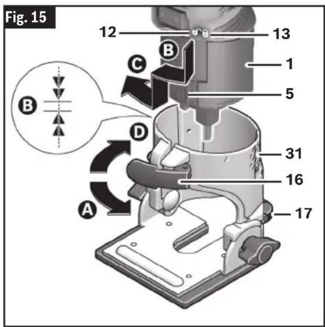
Assembly
cutting depth is reached on the Depth Scale 5.
-
Rotate the Palm Router 1 clockwise until it locks into the Tilt Base 31 and cannot rotate clockwise further©
-
Use the Microfine Adjustment Wheel 17 to precisely reach the desired fine depth on the Depth Scale 5. (Unavailable for Offset Base PR004.)
-
Close the Clamping Lever 16D
Note: The tightness of the clamping lever can be adjusted as needed, see section "Adjusting the Clamping Lever" on page 25.
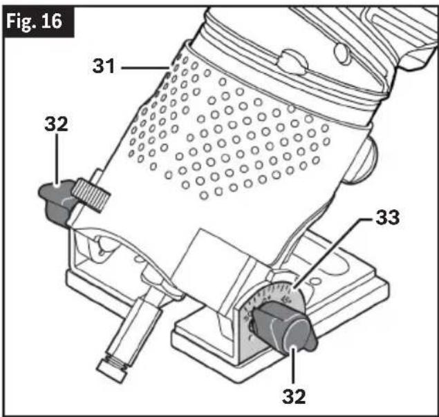
Adjusting the Angle of the Tilt Base
(Fig. 16)
Note: The total tilt range is 75^ , from 45^ forward to 30^ backward.
- Loosen the two Wing Screws 32.
- Adjust to the desired angle using the Angle Scale 33 on the side of the base; there are detents at every 7.5^ .
Whenever possible, the base should be positioned with the Palm Router 1 tilted toward the closed end of the Tilt Base 31. - Tighten the Wing Screws 32. Be careful not to over-tighten or the base may be damaged.
Removing the Palm Router from the Tilt Base
(Fig. 15)
Open the Clamping Lever 16D then reverse steps 1-4 from section "Installing the Palm Router to the Tilt Base" on page 18.
Plunge Base (PR011) and Accessories
Installing the Palm Router to the Plunge Base
(Fig. 17)
- Open the Clamping Lever 16A.
- Align the double arrow on the Palm Router 1 to the double arrow on the Plunge Base 34 then insert the Palm Router 1 into the Plunge Base 34B
- Slightly rotate the Palm Router 1 clockwise until the base aligns with the slot.
- Slide the Palm Router 1 into the base as far as it will go, then rotate the Palm Router 1 clock-wise until it locks into the base ©
- Close the Clamping Lever 16D
Note: The tightness of the clamping lever can be adjusted as needed, see "Adjusting the Clamping Lever" on page 25.
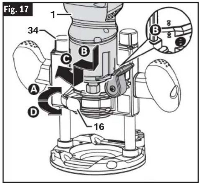
Removing the Palm Router from the Plunge Base
- Reverse steps 1-5 from the section "Installing the Palm Router to the Fixed Base" on page 15.
Installing Plunge Base Groove Routing Dust Extraction Hood (PR012) (optional accessory)
(Fig. 18)
- Insert the Plunge Base Groove Routing Dust Extraction Hood 49 into the opening of the Plunge Base 34 and on top of the Subbase A the dust extraction hood can be installed with the hose outlet facing the front or rear of the base.
- Align the holes on the hood to the holes in the Subbase 21 and secure it in place with the Dust Extraction Thumb Screws 53 B
- Connect the hood to the vacuum using a friction fit nozzle.

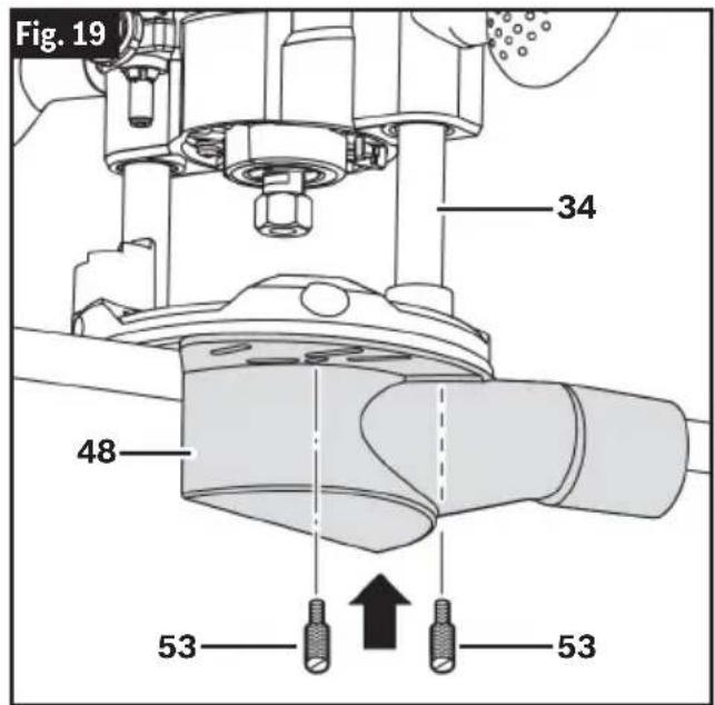
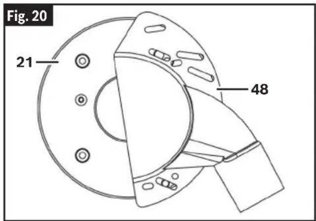
Installing Plunge Base Edge- Forming Dust Extraction (RA1175) (optional accessory)
(Fig. 19, Fig. 20)
The edge-forming hood can be attached in several positions on the subbase according to edge forming operation needs or preferences.
- Position the Plunge Base Edge Forming Dust Extraction Hood 48 underneath the Subbase 21 of the Plunge Base 34 and, depending on the desired placement, align the subbase auxiliary holes with the holes or slots on the dust extraction hood.
- Secure it in place with the Dust Extraction Thumb Screws 53.
- Connect the hood to the vacuum using a friction fit nozzle.
Template Guides for Plunge Base (PR011) (optional accessory)
The plunge base can also be used with the optional Bosch-exclusive quick-change template guide system, which firmly grips the guides with a spring-loaded ring. Unlike conventional threaded template guides, there is no threaded ring that can come loose while routing.
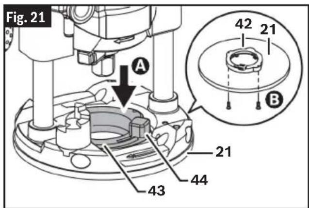
Installing Template Guide Adapter (RA1126) for Plunge Base
(Fig. 21)
- Insert the Template Guide Adapter 43 into the opening of the Plunge Base 34 and on top of the Subbase ☐ the adapter is reversible so the Template Guide Release Lever 44 may be positioned on either side.
- Align the mounting holes then fasten the Template Guide Adapter 43 with the provided screws B
- Make sure that the subbase opening is centered to the Template Guide 45. If adjustment is needed, loosen the Subbase Screws 50 and adjust the location of the Subbase 21, then retighten the Subbase Screws 50.
Note: The centering pin and cone is an optional accessory that enables precision centering of the subbase and template guide. For more information, see section "Centering Pin and Cone (RA1151)".
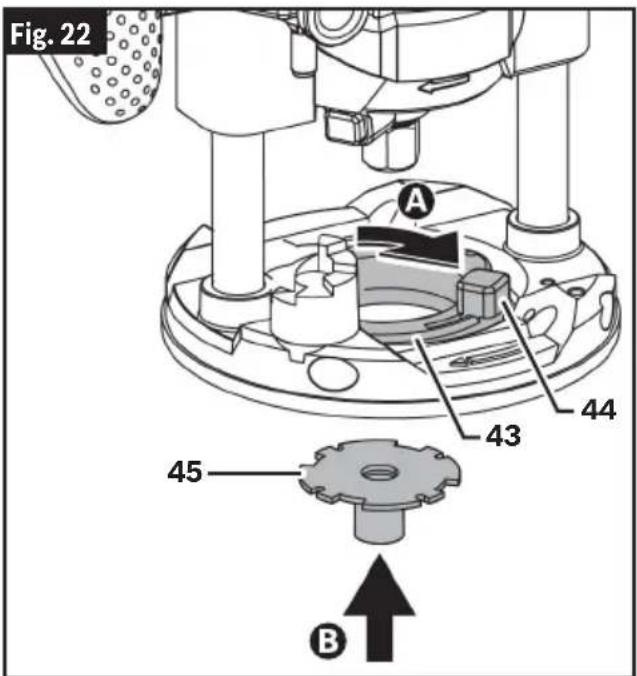
Installing Template Guide (RA1128)
(Fig. 22)
- Pull back and hold the Template Guide Release Lever 44A
- Align the slot configuration and insert the Template Guide 45 into the Template Guide Adapter 43B
- Release the Template Guide Release Lever 44.
- Make sure that the Template Guide 45 is properly secured inside the Template Guide Adapter 43.
Maximum Bit/Cutter Size for Template Guides
When using a template guide, use only router bit with cutters that are 1/16" less than the internal diameter of the template guide, such as in the table below.
Use with Thread Template Guides
Also available as an optional accessory is an additional adapter (RA1100) that allows use of conventional threaded template guides with the Bosch quick-release system.
| Bosch Template Guide | Bushing Depth | External Diameter | Internal Diameter | Max Bit/Cutter Diameter |
| A B B | ||||
| RA1101 3/16” | 5/16” 1/4” | 3/16” | ||
| RA1103 9/64” | 5/16” 17/6 | 4” 13/64” | ||
| RA1105 9/64” | 7/16” 3/8” | 5/16” | ||
| RA1107 5/16” | 7/16” 3/8” | 5/16” | ||
| RA1109 7/16” | 1/2” 13/32” | 11/32” | ||
| RA1111 3/16” | 5/8” 17/32” | 15/32” | ||
| RA1113 1/2” | 5/8” | 17/32” 15/32” | ||
| RA1115 3/16” | 3/4” 21/32” | 19/32” | ||
| RA1117 | 31/64” | 13/16” 5/8” | 9/16” | |
| RA1119 | 31/64” 1” | 25/32” 21/32” | ||
| RA1121 | 7/16” | 1-3/8” | 1-19/64” | 1-15/64” |
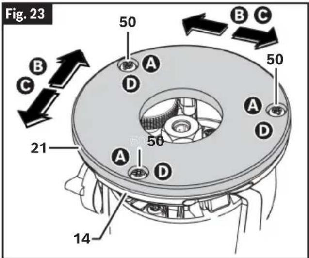
Changing the Subbase
(Fig. 1, Fig. 23)
- Using a screwdriver, unscrew and remove the Subbase Screws 50 A then detach the Subbase 21 from the base.
Note: The quantity of Subbase Screws 50 will vary according to the base model. - Place the new Subbase 21 onto the bottom of the Fixed Base 14.
- Align the mounting holes on Subbase 21 to threaded holes on the base B and loosely screw in the Subbase Screws 50.
- Adjust the location of the Subbase 21 as needed so that the bit and its cutter are centered in the Subbase 21©
- Tighten the Subbase Screws 50 to secure it in place D
Note: The centering pin and cone is an optional accessory that enables precision centering of the Subbase 21 and Template Guide 45. For more information, see "Centering Pin and Cone (RA1151) (optional accessory)."
Centering Pin and Cone (RA1151) (optional accessory)
The Subbase 21, along with the Template Guide 45, can be precisely centered using the optional centering pin and cone to ensure maximum precision.
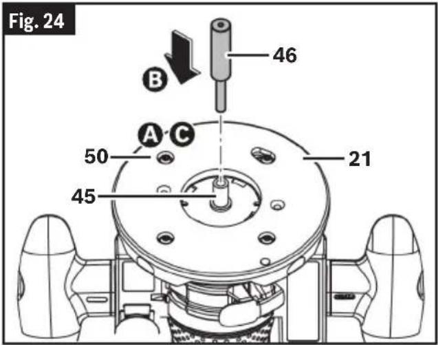
Centering a Template Guide with an Opening Smaller than 1/2"
(Fig. 24)
- Loosen the Subbase Screws 50A
Note: The quantity of Subbase Screws 50 will vary according to the base model. - Insert the narrow end of the Centering Pin 46 into the Template Guide 45 opening and lightly press the Centering Pin 46 into Template Guide 45 to center the Subbase 21 B
- Tighten the four Subbase Screws 50¢
- Remove Centering Pin 46.
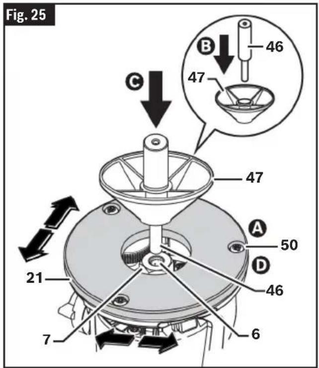
Centering a Subbase or Template Guide with an Opening 1/2" or Larger
(Fig. 25)
- Loosen the four Subbase Screws 50A
- Slide the narrow end Centering Pin 46 into the Cone 47 B
- Insert the narrow end of the Centering Pin 46 into Collet 6 Tighten Collet Nut 7 with fingers to put slight grip on Centering Pin 46.
- Lightly press the Cone 47 into Subbase 21 to center.
- Tighten the four Subbase Screws 50D.
- Remove Centering Pin 46 and Cone 47.
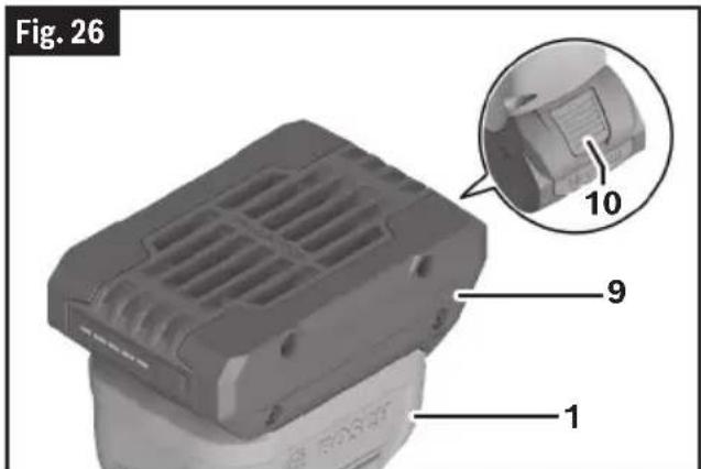
Inserting and Removing the Battery Pack
(Fig. 26)
To Insert the Battery Pack
Slide charged Battery Pack 9 onto the Palm Router 1 until the Battery Pack 9 locks into position.
Your tool is equipped with a secondary locking latch to prevent the Battery Pack 9 from completely falling out of the handle, should it become loose due to vibration.
To Remove the Battery Pack
Press the Battery Pack Release Button 10 and slide the Battery Pack 9 from the Palm Router 1.
Assembly
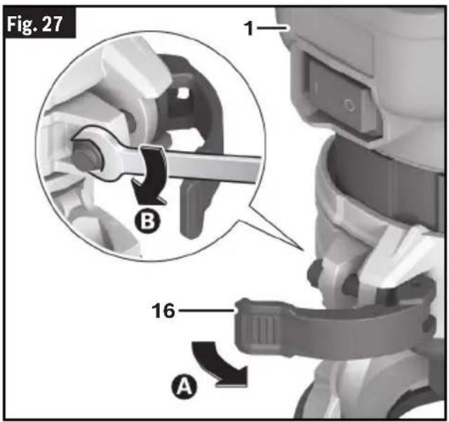
Adjusting the Clamping Lever
(Fig. 27)
If additional clamping force is needed, the Clamping Lever 16 may be tightened.
- Open the Clamping Lever 16A
- Slightly tighten the nut on the Clamping Lever 16 using an 8 mm wrench Ⓑ
- Test the clamping force by installing the Palm Router 1 into the base then closing the Clamping Lever 16. If additional adjusting is needed, repeat steps 1-3 until the Palm Router 1 is secure tightly in the base.
Transportation
WARNING
Always remove the battery pack before transporting. Carry the tool by the handles. Such preventive safety measures reduce the risk of starting
the tool accidentally, which may result in personal injury.
Operation

Disconnect battery pack from tool before assembly, adjustments, troubleshooting or changing accessories. Such preventive safety measures starting the tool accidentally, which may result in personal injury.
reduce the risk of
Use personal protective equipment. Always wear eye protection. Protective equipment such as a dust mask, non-skid safety shoes, hard hat, or used for appropriate conditions will reduce personal injuries.

Setting Depth of Cut
Setting Depth of Cut for Fixed (GKF001) and Tilt (PR005) Base
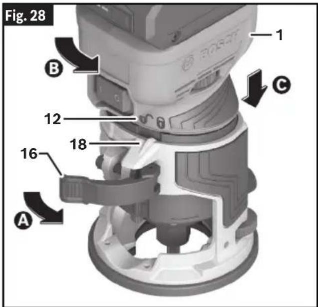
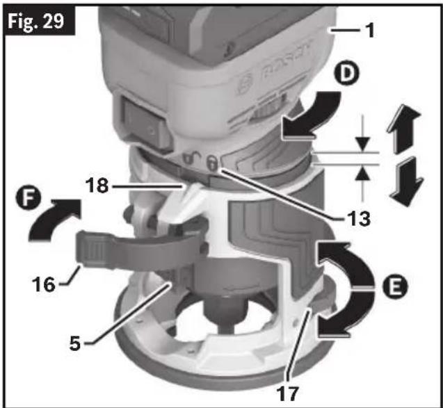
(Fig. 28, Fig. 29)
The depth of cut can be adjusted in rough and fine increments. Rough depth adjustment is possible when the Depth Setting Indicator 18 is aligned with the Unlock Symbol 12 on the Palm Router 1. Fine depth adjustment is possible when the Depth Setting Indicator 18 is aligned with the Lock Symbol 13 on the Palm Router 1. In order to maintain the desired depth setting during application, ensure that the Depth Setting Indicator 18 is aligned with the Lock Symbol 13 on the Palm Router 1 and the Clamping Lever 16 is closed.
- Install the desired router bit. See "Installing/Removing a Router Bit" on page 13.
- Place the router/base assembly on the workpiece.
- Open the Clamping Lever 16A
- While holding the base in place, rotate the Palm Router 1 counter-clockwise until the Depth Setting Indicator 18 aligns with the Unlock Symbol 12 (rough depth adjustment setting).
- Slowly lower the router until the router-bit touches the workpiece ©
- Note the reading on the Depth Scale 5 and add the desired depth-of cut to this value to determine the target scale value.
- Lift the router/base assembly from the workpiece and push the Palm Router 1 into the base until the target scale value is reached.
- Rotate the base clockwise until it locks into the Palm Router 1① the Depth Setting Indicator 18 will align with the
Lock Symbol 13 (fine depth adjustment setting) on the router.
- If necessary, use the Microfine Adjustment Wheel 17 to precisely reach the desired depth on the Depth Scale 5; each complete rotation of the dial equals 1.25 mm (approximately 3/64).
- Close the Clamping Lever 16F
Note: The tightness of the clamping lever can be adjusted as needed. See "Adjusting the Clamping Lever" on page 25.
- Ensure that the Palm Router 1 is secured tightly in the base.
- Make a trial cut to verify that the Palm Router 1 is set to the desired depth.
Operation
Setting Depth of Cut for Plunge Base (PR011)
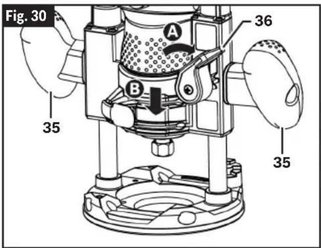
(Fig. 30)
- To lower, push down the Plunge Lock Lever 36 🐃 apply downward pressure using the Plunge Base Grips 35 until you reach desired depth Ⓑ then release Plunge Lock Lever 36. The Plunge Lock Lever 36 is spring loaded and returns automatically to the locked position.
- To raise the router, push down the Plunge Lock Lever 36, release pressure on the Plunge Base Grips 35 and the Palm Router 1 will automatically retract the bit from the workpiece. It is advisable to retract the bit whenever it is not engaged in work piece.
Using the Rod and Turret for Plunge Base
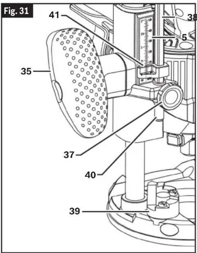
(Fig. 30, Fig. 31)
The depth rod and the depth stop turret are used to control cutting depth as follows:
- With the bit installed, push down the Plunge Lock Lever 36 and apply downward pressure using the Plunge Base Grips 35 until the tip of the router bit just contacts the level surface the router is sitting on, then release the Plunge Lock Lever 36. This is the "zero" position, from which further depth adjustments can be accurately made.
- Rotate the Depth Stop Turret 39 until the desired step is aligned with the Depth Rod 38; use taller steps for more shallow plunge depths or first pass for deeper cuts.
Note: The two screws in the turret can be adjusted create custom step heights.
- Loosen the Thumb Screw 37 and lower the Depth Rod 38 until it contacts the step of the turret.
- Slide the Depth Indicator 41 until the red line indicates zero on the Depth Scale 5, indicating the point at which the bit just contacts the work piece.
Operation
- Slide the Depth Rod 38 up until the red line on the Depth Indicator 41 reaches the desired cutting depth and secure the rod in position by firmly tightening the Thumb Screw 37.
- The desired depth of cut may now be achieved by plunging the router until the Depth Rod 38 contacts the turret.
Alternate Set-up for Depth of the Rod and Turret
(Fig. 31)
- Place a jig at the desired routing depth (such as a hinge which needs to be mortised) on the bottom step of the turret.
- Loosen the Thumb Screw 43 then lower the Depth Rod 44 until it contacts the jig.
- Secure the rod in position by firmly tightening the Thumb Screw 43.
- Remove the jig.
Rod and Turret Fine Depth Adjustment
The plunge base is equipped with a fine adjustment system that allows you to micro adjust the plunge depth of the router bit for superior routing accuracy.
Each complete revolution of the fine adjustment knob adjusts the plunging depth by 1/32", and each of the four indicator marks on the knob represents 1/128".
To use the fine adjustment knob:
- To prepare for fine depth adjustments, turn the Fine Adjustment Knob 40 four revolutions clockwise so adjustments can be made in either direction.
- Follow the steps in "Using the Rod and Turret for Plunge Base" on page 27 to set up the Plunge Base to the desired depth.
- Push down the Plunge Lock Lever 36 and apply downward pressure using the Plunge Base Grips 35 until the end of the Depth Rod 38 touches the Depth Stop Turret 39.
-
Loosen the Thumb Screw 37.
-
To increase the plunge depth, turn the Fine Adjustment Knob 40 counter-clockwise until the red line on the Depth Indicator 41 reaches the desired cutting depth, then slide the Depth Rod 38 down until the end touches the Depth Stop Turret 39.
-
To decrease the plunge depth, turn the Fine Adjustment Knob 40 clockwise until the red line on the Depth Indicator 41 reaches the desired cutting depth.
-
Once the desired cutting depth is reached, secure the rod in position by firmly tightening the Thumb Screw 37.
Note: The fine adjustment stop cannot be used to reduce the plunge depth when the depth rod is already touching the depth stop turret. The router must be raised before such an adjustment can be made.
Deep Cuts
For deep cuts, make several progressively deeper cuts by starting at one depth and then make several subsequent passes, increasing the cutting depth with each pass. To be certain that your depth settings are as desired, you may want to make test cuts in scrap material before beginning work.
Operation
Operating the Palm Router
(Fig. 32)
On/Off Switch
Your tool can be turned "ON" or "OFF" by the On/Off switch located on the motor housing. One side of the switch is marked "I" for "ON", and the other side of switch is marked "O" for "OFF".
- TO TURN THE TOOL "ON": Push the side of the Switch 3 marked "I".
- TO TURN THE TOOL "OFF": Push the side of the Switch 3 marked "O".
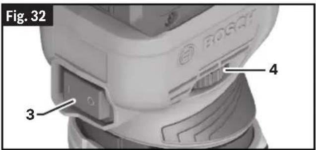
Constant Electronic Control
(Fig. 32)
The Constant Electronic Control keeps the speed at no load and under load virtually consistent, guaranteeing uniform performance.
Variable Speed Dial
(Fig. 32)
The electronic speed control feature allows motor speed to be matched to cutter size and material hardness for improved finish, extended bit life, and higher performance. Speed can be changed while palm router is turned on. Be sure to adjust the speed only when the bit is not in contact with the cutting surface.
- To increase the speed of the palm router, rotate the Variable Speed Dial 4 to the to the right; the numbers on the dial will increase.
- To decrease the speed of the palm router, rotate the Variable Speed Dial 4 to the to the left; the numbers on the dial will decrease.
The chart below indicates RPM speed to the setting number on the dial.
| Dial Position RPM Speed |
| 1-2 10,000-14,000 |
| 3-4 18,000-24,000 |
| 5-6 26,000-30,000 |
The following speed chart indicates the relation between settings and application; exact settings are determined by operator experience and preference. Also refer to the router bit manufacturer for recommend speed in relation to the application.
WARNING
Never operate router bits at speeds that are
higher than their maximum rated speed. Router bits running faster than their rated speed can break and fly apart.
| Material | Router Bit Diameter | Variable Speed Dial Position |
| Hardwood | 0.16"-0.39" 5 | -6 |
| 0.47"-0.78" 3 | -4 | |
| >0.78" 1-2 | ||
| Softwood | 0.16"-0.39" 5 | -6 |
| 0.47"-0.78" 3 | -6 | |
| >0.78" 1-3 | ||
| Particleboard | 0.16"-0.39" 3 | -6 |
| 0.47"-0.78" 2 | -4 | |
| >0.78" 1-3 | ||
| Plastics | 0.16"-0.59" 2 | -3 |
| >0.59" 1-2 |
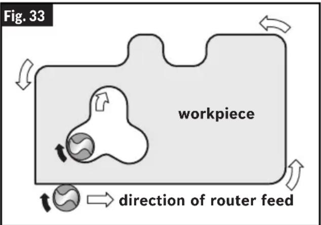
Feeding the Palm Router
(Fig. 33)
This section explains concepts of how to properly feed the palm router while in operation.
Make sure to read the corresponding sections for detailed operational steps for each base type.
As seen from the top of the palm router, the bit turns clockwise and the bit's cutting edges are positioned to best cut into the workpiece. Therefore, the most efficient cut is made by feeding the palm router so that the bit turns into the workpiece, not away. The following figure shows proper feed for various cuts. How fast you feed depends on the hardness of the material and the size of the cut. For some materials, it is best to make several cuts of increasing depth.
If the palm router is hard to control, heats up, runs very slowly or leaves an imperfect cut, consider these causes:
- Wrong direction of feed — hard to control.
- Feeding too fast – overloads motor.
- Dull bit – overloads motor.
- Cut is too large for one pass – overloads motor.
- Feeding too slow – leaves friction burns on workpiece.
Feed smoothly and steadily (do not force).
Practice and experience will help with familiarizing how the palm router sounds and feels when it is working best.
Always hold the palm router off the workpiece when turning the switch on or off.
Contact the workpiece with the router after the palm router has reached full speed, and remove it from the workpiece before turning the switch off. Operating in this manner will prolong switch and motor life and will greatly increase the quality of your work.
The Constant Electronic Control feature allows motor speed to be matched to cutter size and material hardness for improved finish, extended bit life, and higher performance.
Rate of Feed
When routing or doing related work in wood and plastics, the best finishes will result if the depth of cut and feed rate are regulated to keep the motor operating at high speed. Feed the palm router at a moderate rate. Soft materials require a faster feed rate than hard materials. The router may stall if improperly used or overloaded. Reduce the feed rate to prevent possible damage to the tool. Always be sure the collet nut is tightened securely before use. Always use router bits with the shortest cutting length necessary to produce the desired cut. This will minimize router bit run-out and chatter. It may be necessary to make the cut in more than one pass with progressively deeper settings to avoid overloading the motor. If the bit cuts freely and the motor does not slow down, the cutting depth is generally correct.
Operation
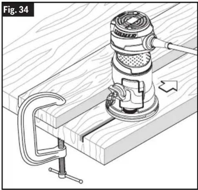
Guiding the Palm Router
(Fig. 34)
The router can be guided through the workpiece in any of several ways. The method you use depends, of course, on the demands of the particular job and on convenience. For routing operations such as grooving or dadoing, it is often necessary to guide the tool in a line parallel to a straight edge. One method of obtaining a straight cut is to securely clamp a board or other straightedge to the work surface, and guide the edge of the router sub-base along this path.
natural_image
Technical illustration of a mechanical clamp or clamping device mounted on a wooden base, showing no text or symbols.Using the Palm Router with Fixed Base (GKF001) and Accessories
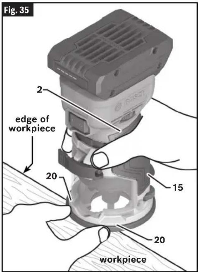
Using the Palm Router with Fixed Base
(Fig. 1, Fig. 35)
- Install the router bit. See "Installing/Removing a Router Bit" on page 13.
- Adjust the cutting depth. See "Setting Depth of Cut" on page 26.
- Install the Battery Pack 9.
- Grip the Palm Router 1 firmly using either the Palm Router Grip Area 2 or the Fixed Base Grip Area 15.
Note: In addition to main grip areas, the Fixed Base has Finger Support Pockets 20 to provide additional stability for the router. The pockets feature finger guards to provide a barrier between the finger pockets and the bit area.
- Adjust the speed. See "Variable Speed Dial" on page 29.
- Switch the Palm Router 1 on. See Fig. 32 on page 29.
Operation
- Feed the Palm Router 1 into the workpiece. See "Feeding the Palm Router" on page 30.
Note: the speed may be adjusted while the palm router is in operation.
- Once routing is complete, turn the Palm Router 1 off. See “(Fig. 32)” on page 29.
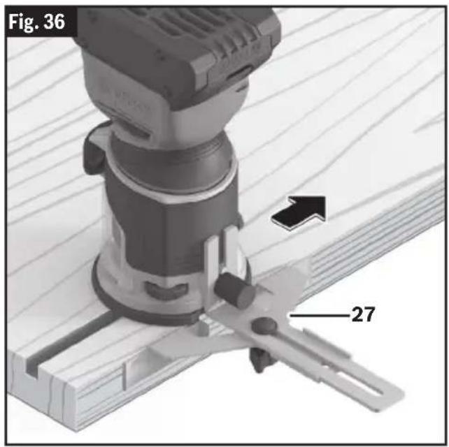
Straight Edge Guide (PR102) (optional accessory)
(Fig. 36)
The Straight Edge Guide 27 is an optional accessory that will guide the palm router parallel to a straight edge.
The guide features a scale for accurately positioning the edge guide relative to the bit. With the guide installed and adjusted, the router should be fed normally, keeping the guide in contact with the edge of the workpiece at all times.
The router guide can also be positioned directly under the router base for operations where a cut is needed close to or at the edge of the work, such as when rounding off deck planks. For complete instructions on installation and operation, please refer to the instructions included with this accessory.
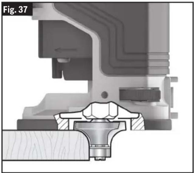
Self-Piloted Bits
(Fig. 37)
Self-piloted bits have an integral round tip or ball bearing which rides against the work surface above or below the cutter to control horizontal cutting depth. When using these bits, neither the roller guide or the straight edge guide is required. When guiding against a laminated surface, use wax or other lubricant and do not apply excess pressure or the piloted end may mar the work. Bearing pilots must be kept clean and free of adhesive or other residue. Router bit bearings are sealed and permanently lubricated, and should be replaced when they no longer turn freely to avoid damaging the work surface.
natural_image
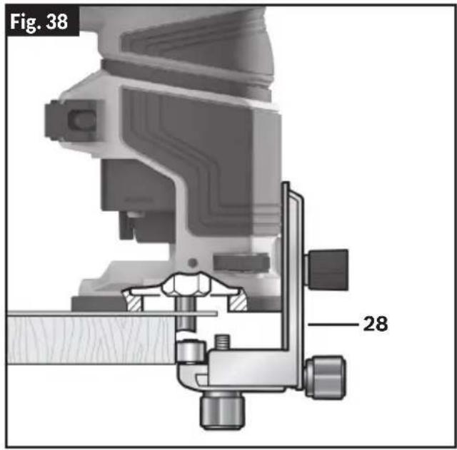
Mechanical assembly diagram showing a valve and housing component (no text or symbols)Fixed Base Roller/Bushing Guide (PR003) (optional accessory)
(Fig. 38)
The optional Fixed Base Roller/Bushing Guide 28 is used when edge-forming or trimming with unpiloted/non-bearing bits.
With the fixed Base roller/bushing guide installed and adjusted, the router should be fed normally, keeping the guide in contact with the edge of the workpiece at all times.
To maintain a consistent width of cut, a consistent angle must be maintained between the router and the workpiece.
For complete instructions on installation and operation, please refer to the instructions included with this accessory.
Operation
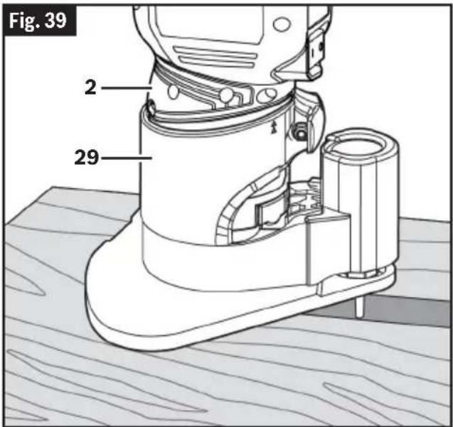
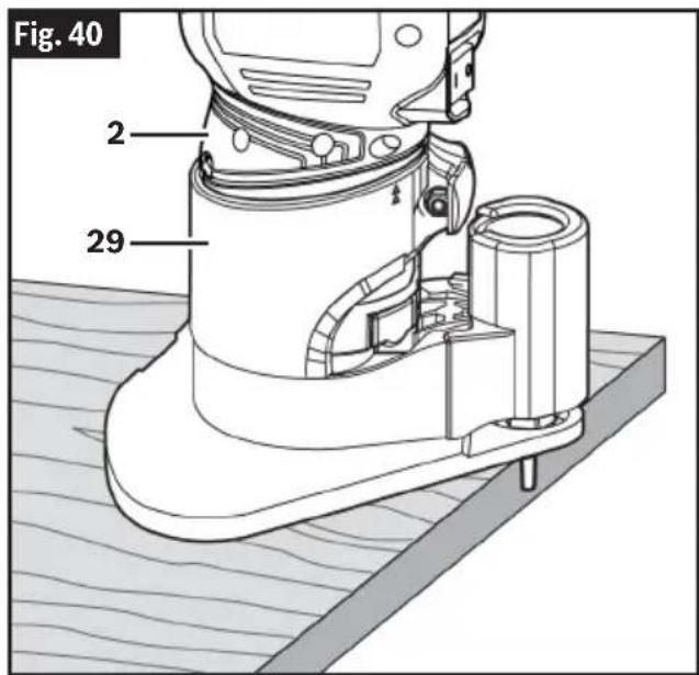
Using the Palm Router with Offset Base (PR004)
(Fig. 39, Fig. 40)
WARNING To reduce the risk of injury, do not use the off-
set base for more than 10 minutes continuously. Prolonged continuous use will result in the tool becoming hot to the touch.
The offset base is designed for routing in confined areas, especially for trimming laminates in areas that are inaccessible with the standard fixed base, such as locations that are close to adjacent vertical surfaces like as the tops of already-installed counter backsplash backsplashes.
The offset base allows routing extremely close to vertical surface in front of the
Operation
tool, as close as 1/2" when 3/4" bit is used (Removal of the black offset spindle cover further reduces distance from 3/4" bit and vertical surface to 3/8".) The 1-1/16" base opening makes it possible to use bits that have cutters as wide 13/16".
The offset base can also be used to scribe the back of a new counter backsplash so that it will mate precisely with the wall against which it will rest.
The nature of a belt drive mechanism, like the one in the offset base, is different than a typical palm router base. To help minimize heat build-up, the offset base has been designed with large bearings, specially-designed heat sinks, carefully-directed airflow and plastic heat shields. Depending on the application, the offset base can be used for up to about 10 minutes continuously before it will need to be left idle so that it can cool off.
The principles of using the offset base are basically the same as for the fixed base router setup (palm router in fixed base assembly, see “Using the Palm Router with Fixed Base” on page 31, with the following differences:
- Grip the Offset Base 29 with one hand using Palm Router Grip Area 2 and the other hand gripping the back of the base housing or the top of the offset spindle.
- For routing backsplashes and other elevated workpieces, some installers mount the offset base to a wood block that matches the height of the laminated backsplash. This helps to maintain a consistent angle between the bit's cutter and the workpiece; this also provides addition stability.
Note: Cutting with an offset base does not require changes in depth.
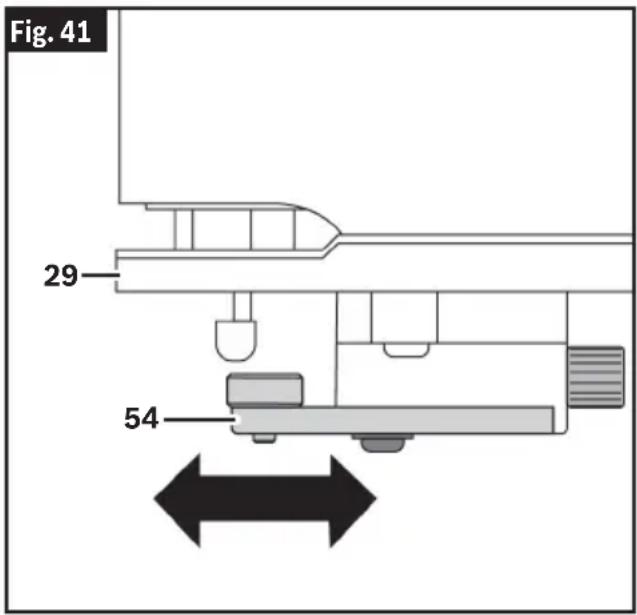
Offset Base Roller/Bushing Guide (optional accessory)
(Fig. 41)
The offset base roller/bushing guide is required when edge-forming or trimming with unpiloted non-bearing bits.
- Install the Offset Base Roller/Bushing Guide 54 to the Offset Base 29 and adjust it as needed, see section "Attaching the Offset Base Roller/Bushing Guide" on page 17 and "Adjusting the Offset Base Roller/Bushing Guide" on page 18.
- The router should be fed normally, keeping the guide in contact with the edge of the workpiece at all times. See “Feeding the Palm Router” on page 30.
- To maintain a consistent width of cut, a consistent angle must be maintained between the router and the workpiece.
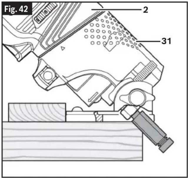
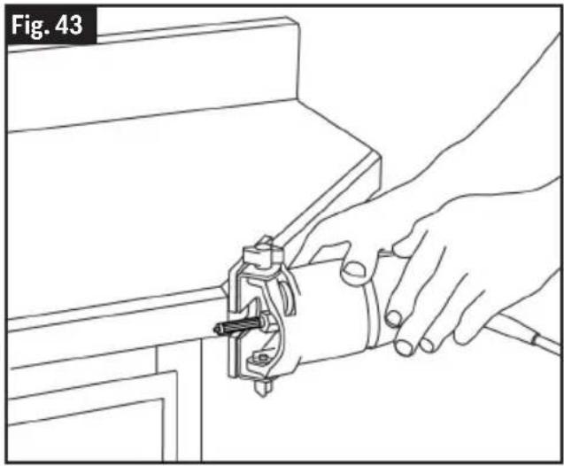
Using the Palm Router with Tilt Base (PR005)
(Fig. 42, Fig. 43)
WARNING
To reduce the risk of in- jury, never grip the base directly above or next to the exposed bit.
The principles of using the tilt base are basically the same as for the fixed base router set-up. See "Using the Palm Router with Fixed Base" on page 31 with the following differences:
- A palm router in a Tilt Base 31 should always be used with a self-piloted or bearing bit.
- The cutting angle must be adjusted. See "Adjusting the Angle of the Tilt Base" on page 19.
• Always grip the Palm Router 1 firmly using the Palm Router Grip Area 2. The proper grip position will depend on the angle of the cut. - Feed the Palm Router 1 into the workpiece. See "Feeding the Palm Router" on page 30. When trimming edges while the bit is tilted toward the direction of feed, it is extremely important to keep the base square with the surface to be routed. If the tilt router is shifted in the direction of the surface it is riding on, the upper part of the cutter can dig far into the workpiece.
natural_image
Line drawing of a hand using a clamp to adjust or install a component, labeled Fig. 43 (no text or symbols on the diagram itself)Operation
Using the Palm Router with Plunge Base (PR011) and Accessories
(Fig. 44)
Using the Palm Router with Plunge Base
- Install the router bit. See "Installing/Removing a Router Bit" on page 13.
- Adjust the cutting depth. See "Setting Depth of Cut" on page 26.
- Install the Battery Pack 9.
- Grip the Plunge Base 34 firmly using both Plunge Base Grips 35.
- Adjust the speed. See "Variable Speed Dial" on page 29.
- Switch the Palm Router 1 on. See “(Fig. 32)” on page 29.
- Allow the palm router bit to reach full speed before plunging the cutter head into the workpiece.
- Push down the Plunge Lock Lever 36 and plunge the router down until the router bit reaches the set depth.
- Release the Plunge Lock Lever 36.
- Perform the routing operation. See "Feeding the Palm Router" on page 30.
Note: the speed may be adjusted while the palm router is in operation. - Once routing is complete, unlock the Plunge Lock Lever 36 so the router bit disengages the workpiece.
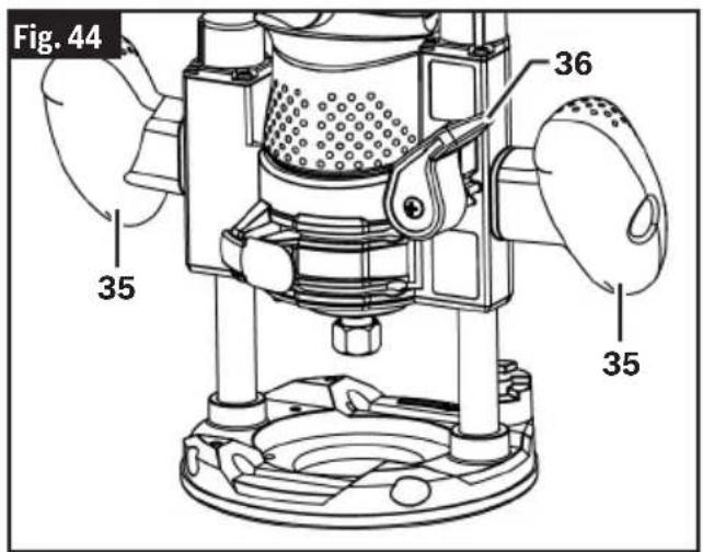
- Turn the Palm Router 1 off. See “(Fig. 32)” on page 29.
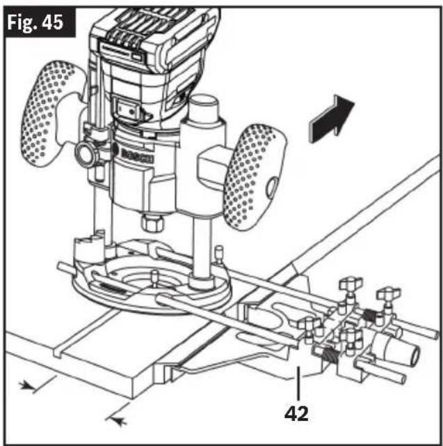
Deluxe Router Guide (RA1054) (optional accessory)
(Fig. 45)
The Bosch deluxe router guide is an optional accessory that will guide the palm router parallel to a straight edge or allow you to create circles and arcs.
With the Deluxe Router Guide 42 installed and adjusted, the router should be fed normally, keeping the guide in contact with the edge of the workpiece at all times. See "Feeding the Palm Router" on page 30. The deluxe router guide may also be positioned directly under the router base for operations where a cut is needed close to or at the edge of the work.
The deluxe router guide includes a dust extraction hood and the VAC002 vacuum hose adapter.
For complete instructions on installation and operation, please refer to the instructions included with this accessory.
Maintenance

To avoid accidents, always disconnect the battery pack from the tool before cleaning or performing any maintenance.

Never immerse your tool, battery pack, or charger in liquid, or allow liquid to flow inside them.
General maintenance
Keep your palm router, accessories, battery pack and charger in good working order by adopting a regular maintenance program. Inspect your palm router for issues such as undue noise, binding of moving parts, breakage of parts, or any other condition that may affect palm router operation.
If the palm router does not start or operate at full power with a fully charged battery pack, clean the contacts on the battery pack. If the palm router still does not work properly, return the palm router, charger and battery pack, to a BOSCH service facility for repairs.
Service

NO USER SERVICEABLE PARTS INSIDE. Mainte-
nance performed by unauthorized personnel may result in misplacing of internal wires and components which could cause serious hazard. We recommend that all tool service be performed by a Bosch Factory Service Center or Authorized Bosch Service location.
Cleaning
Certain cleaning agents and solvents damage plastic parts. Some of these are: gasoline, carbon tetrachloride, chlorinated cleaning solvents, ammonia and household detergents that contain ammonia.
Periodically remove dust from the tool by wiping with a clean rag or using compressed air on the inside of the base and motor unit as well as the fine depth adjustment system.
Remove dust and debris from all vents. Keep the palm router clean, dry and free of oil or grease. Use only mild soap and a damp cloth to clean the palm router, since certain cleaning agents and solvents are harmful to plastics and other insulated parts. Some of these include gasoline, turpentine, lacquer thinner, paint thinner, chlorinated cleaning solvents, ammonia and household deter-
gents containing ammonia. Never use flammable or combustible solvents around tools.
Storage and Maintenance
Store palm router and accessories in a cool dry place and avoid freezing. Before use, check router bits for cracks and fractures, do not use if damage is suspected.
Repairs
For repairs, return the palm router, battery pack and charger to the nearest Bosch service center, or Authorized Bosch Service location.
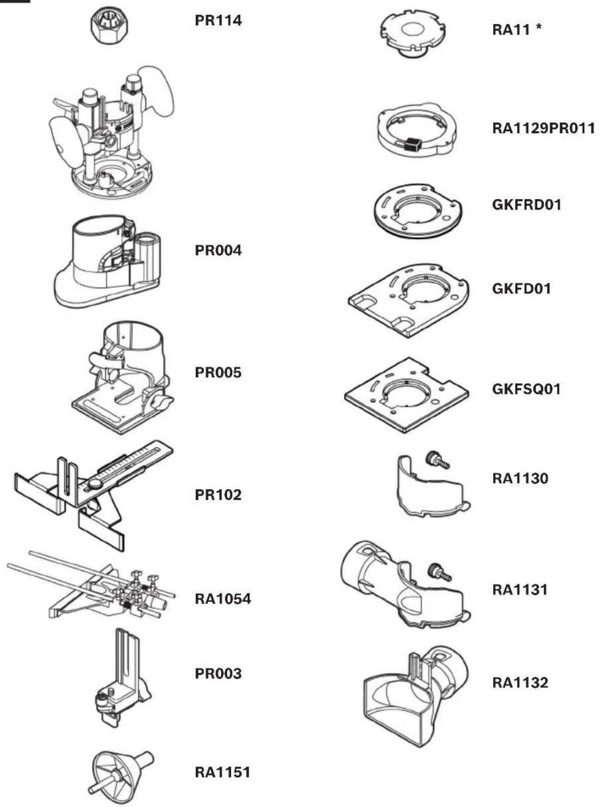
Accessories
WARNING
Do not use attachments/accessories other than those specified by
Bosch. Use of attachments/accessories not specified for use with the tool
described in this manual may result in damage to tool, property damage, and/or personal injury.
Fig. 46
Troubleshooting
WARNING
Disconnect battery pack from tool before assembly, adjustments, troubleshooting or changing accessories. Such preventive safety measures
reduce the risk of starting the tool accidentally, which may result in personal injury.
| Trouble Cause Corrective Action | ||
| Palm router does not operate. | No battery inserted/battery discharged. | Insert charged battery. |
| Battery and tool temperature too high/low. | Allow battery and/or palm router to reach permitted operating temperature. See “Specifications” on page 12. | |
| Palm router does not turn on: LED work light blinking. | Spindle Lock Lever in Lock Position. | Turn switch off. Push Spindle Lock Lever to Unlock Position. Turn switch on. |
| Battery inserted with switch in on position. | Turn switch off. Remove battery. Insert battery. Turn switch on. | |
| Palm router operates intermittently. | Battery not fully charged. Charge | battery. |
| Internal error. | Return to Bosch service center for service. | |
| Palm router operates for a short time or at a decreasing rate per battery charge. | Battery not fully charged. Charge | battery. |
| Battery worn. Replace battery. | ||
| Palm Router is hard to control. | Incorrect direction of feed. | Reverse the direction of feed. See “Feeding the Palm Router” on page 30. |
| Palm router runs slow; rough cuts, poor cutting performance. | Dull or damaged router bit. Replace router bit. | |
| Palm router is overloaded. | Back off the workpiece to reduce the load. | |
| Feeding too fast, adjust the speed of feed or the palm router's speed setting. | ||
| Cut is too large for one pass. Make multiple progressively deeper cuts. | ||
| Friction burns on the workpiece. | Feeding too slow. | Adjust the speed of feed or the palm router's speed setting. |
natural_image
Technical line drawing of a mechanical assembly with rods and brackets (no text or symbols)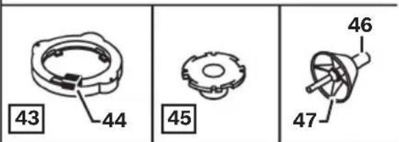
Rod and Turret Fine Depth Adjustment
natural_image
Technical illustration of a mechanical clamp or clamping device mounted on a wooden base, showing no text or symbols.natural_image
Mechanical assembly diagram showing a bolted joint inserted into a housing (no text or symbols visible)natural_image
Line drawing of a hand using a clamp to adjust or install a component, labeled Fig. 43 (no text or symbols on the diagram itself)Base inclinable (PR005)....94
natural_image
Technical line drawing of a mechanical assembly with rods and brackets (no text or symbols)
natural_image
Technical illustration of a mechanical clamp or clamping device mounted on a wooden base, showing no text or symbols.natural_image
Mechanical assembly diagram showing a valve and base mount (no text or symbols)natural_image
Line drawing of a hand using a clamp to adjust or install a mechanical component (no text or symbols)For details on the terms of the limited warranty for this product, go to https://rb-pt.io/PowerToolWarranty or call 1-877-BOSCH99.